ET-3200 Digital Trainer · Volume 4
The Courses and the Bench
The ET-3200 has no calibration procedure. Its one adjustment, setting +12 V with a single control, is covered in volume 3. How to use it was taught by the course it was sold with. This volume covers that course and its classroom and later forms, describes how an experiment was carried out on the trainer, and sets out what the trainer offered once the course was finished. The ET-3200 was the second trainer in Heath’s curriculum, after the analog ET-3100, and the sequence of courses is described from the digital side here. The analog courses (EE-3101 to EE-3106) are covered in the ET-3100 dive.
4.1 Heathkit Continuing Education
Heath’s education business had a single founder. Lou Frenzel wrote that he left McGraw-Hill in 1973 and joined Heath “to start Heath’s education and publishing business”, with “a line of self-study courses in electronics with kit trainers”. He described it as “a great success with individuals and technical colleges” (Frenzel, Electronic Design, 30 December 2013). The company’s own later account, as reported in 2008, dates the start of educational sales to 1974 and calls the business “an outgrowth of the instructions that accompanied its electronic kits” (history dive, volume 7). The public launch was the Christmas 1975 catalogue described in volume 1.
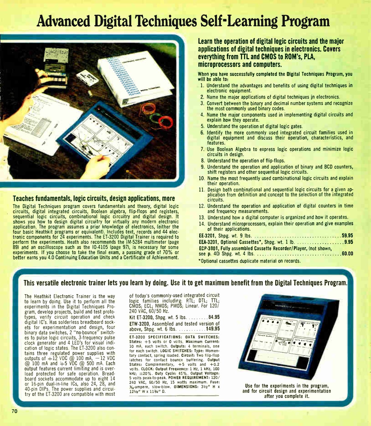
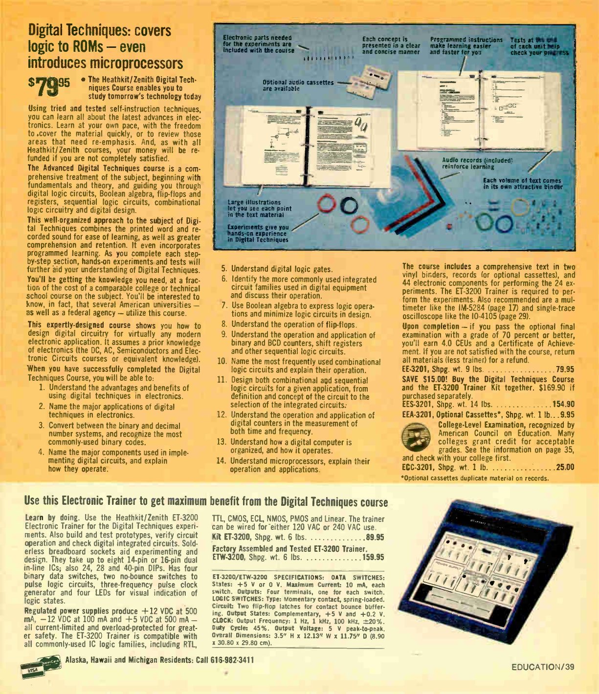
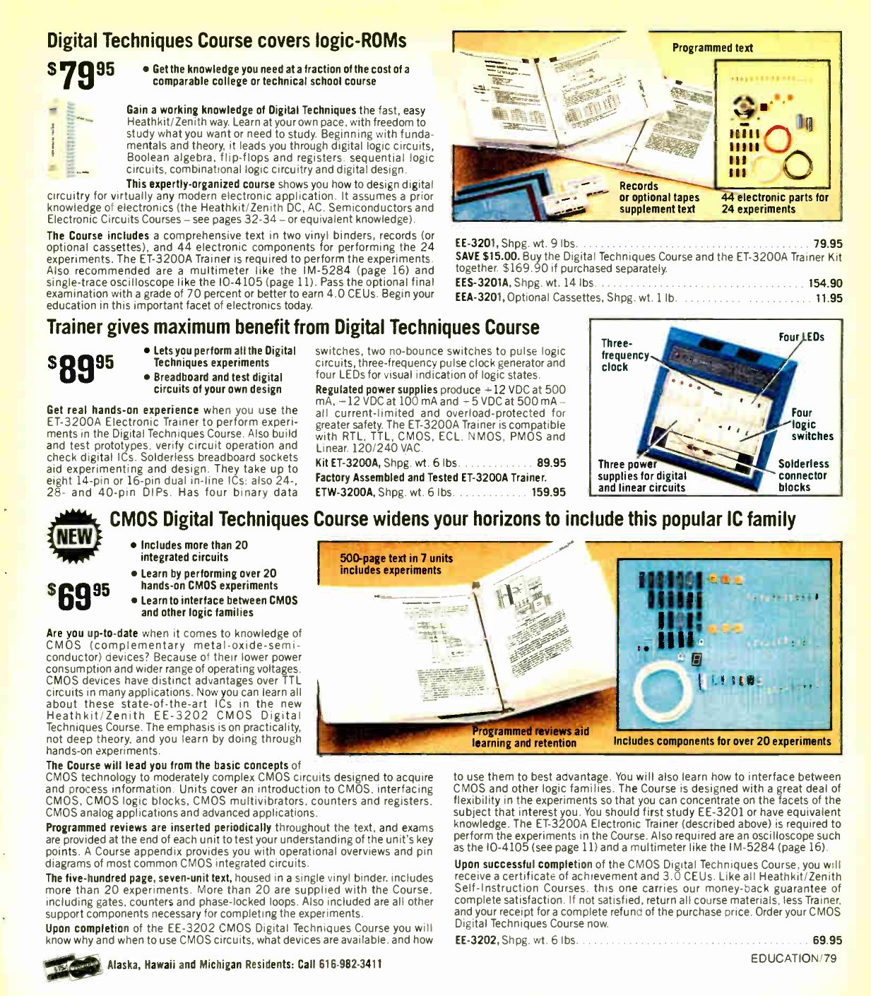
The format was the same across the range. Each course was an “Individual Learning Program”: a programmed text in ring binders, with short sections, review questions and answers, and unit examinations. It came with audio records (later optional cassettes) for spoken overviews and reviews, and a bag of every component the experiments needed. An optional final examination, returned to Heath and passed at 70 per cent, earned a Certificate of Achievement and Continuing Education Units. By 1981 the self-instruction courses carried a “complete money-back guarantee of satisfaction”. For an extra fee, a College-Level Examination “recognized by American Council on Education” let a student seek academic credit. For Digital Techniques it was ECC-3201, at $25.00 (Winter 1981 catalogue, p. 39).
4.2 EE-3201 Digital Techniques (1975)
The first digital course had ten “Unit-Subjects”. The Christmas 1975 catalogue lists them (p. 65):
- Introduction: techniques and use, binary numbers, digital codes.
- Semiconductor Devices for Digital Circuits.
- Digital Logic Circuits: AND gates, OR gates, NAND/NOR logic.
- Digital Integrated Circuits: TTL, ECL, CMOS, nMOS, pMOS, and how to choose among them.
- Boolean Algebra.
- Flip-Flops and Registers: latches, D and JK flip-flops, storage registers.
- Sequential Logic Circuits: binary, BCD and modulo-N counters, up/down counters, dividers, shift registers.
- Combinational Logic Circuits: encoders, decoders, exclusive-OR, comparators, multiplexers, ROMs, PLAs.
- Digital Design: procedures for designing combinational and sequential circuits.
- Digital Applications: test equipment, digital counters, digital computers, microprocessors.
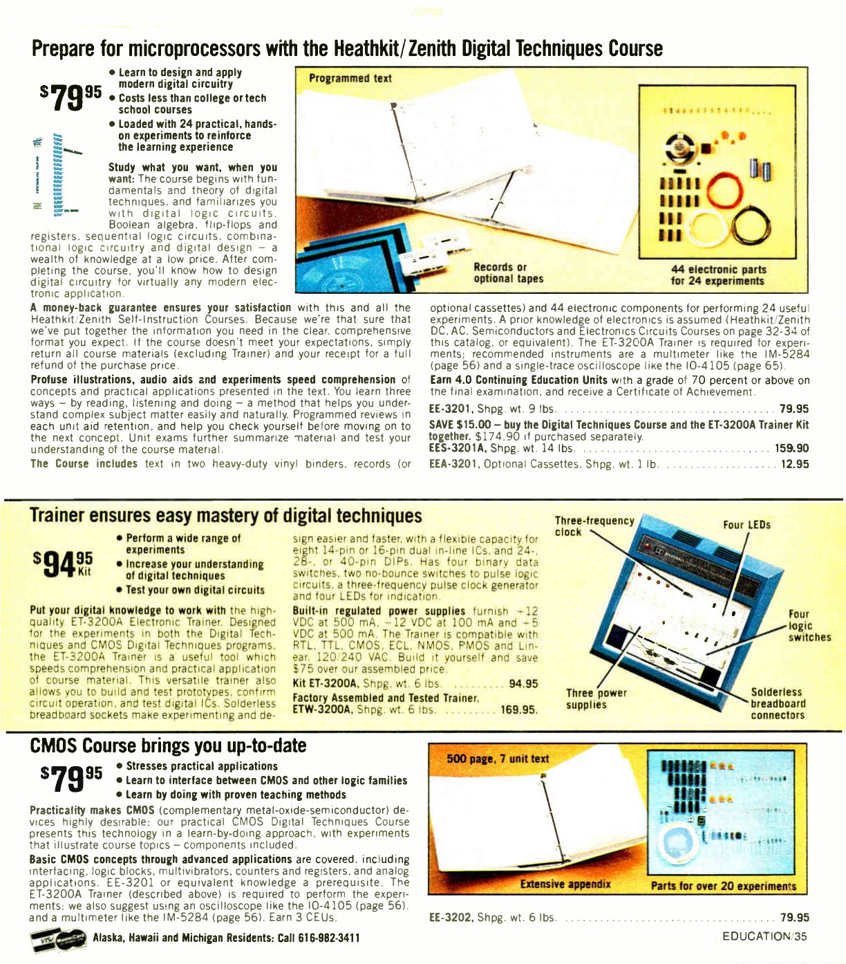
The course cost $49.95. The catalogue gave its “average min. completion time” as 40 hours and its credit as 4.0 CEU, the largest of any course in the first announcement. The student needed a VOM (Heath suggested its IM-17), a soldering iron and small tools, a record player, and the trainer. By Fall 1977 the package was described as “text, records and 44 parts for 24 different experiments”. Optional cassettes (EEA-3201) duplicating the records cost $6.95. By Spring 1978 Heath described it as “the most advanced of Heath’s courses and the nucleus of future electronics; digital electronics” (Fall 1977, p. 100; Spring 1978, p. 103).
No scan of the original 1975 EE-3201 text was found online. Its content is known from the catalogue outlines and from the 1983 revision, which keeps most of the structure.
4.3 The classroom version: EB-6201
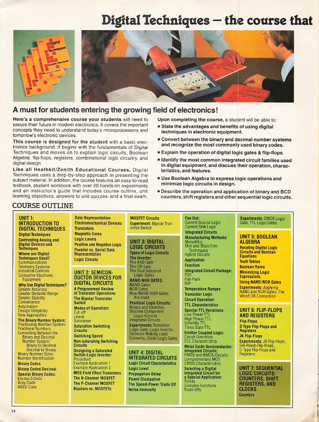
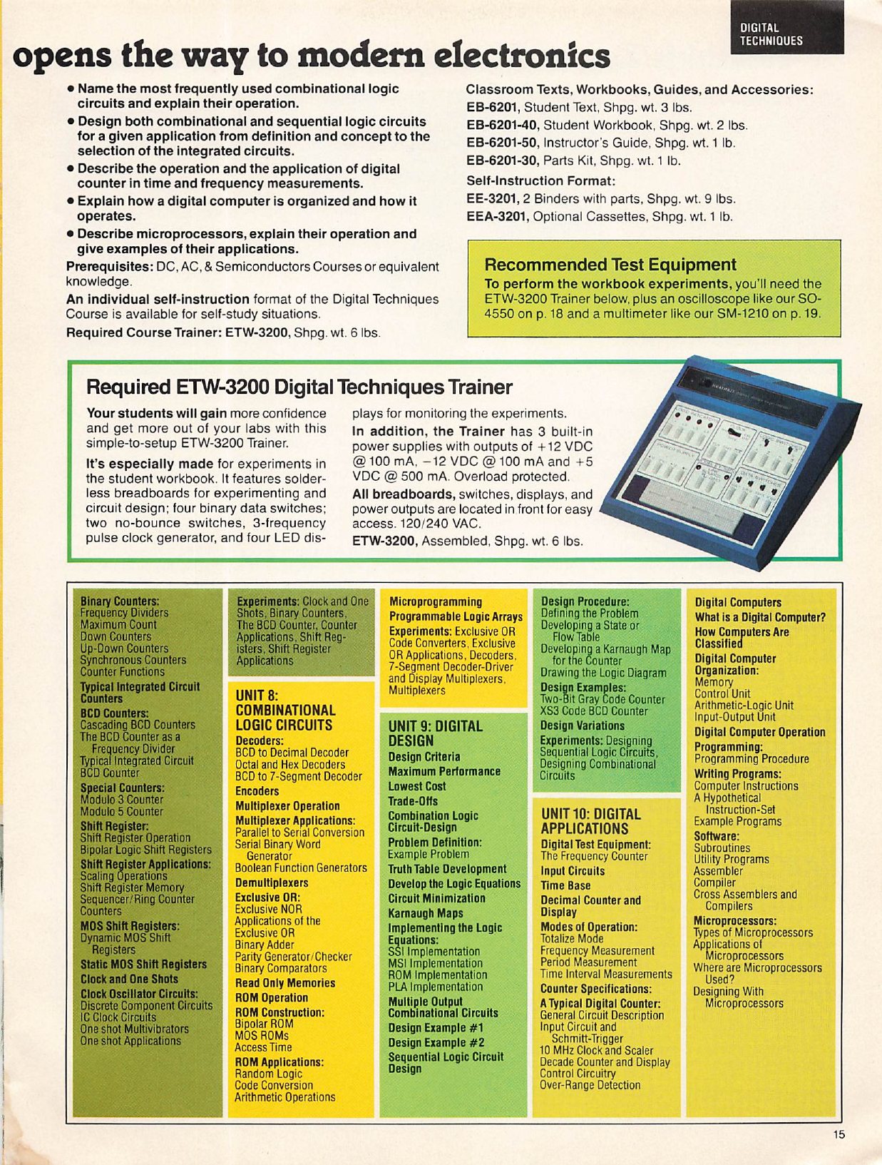
In 1978 Heath began repackaging its home courses for schools and industrial training. The Spring 1978 catalogue announced “Famous Heath Electronics Courses, now designed for Classroom Use”. By Fall 1979 a full page offered “Classroom versions of our Educational Programs — Ideal for schools and industrial training”, with separate student texts, student workbooks, instructor’s guides and parts packs, and a state-by-state list of Heath representatives (Spring 1978, p. 103; Fall 1979, p. 71). The Digital Techniques classroom set was:
Table 1 — In 1978 Heath began repackaging its home courses for schools and industrial training. The Spring 1978 catalogue announced "Famous Heath Electronics Courses, now designed for Classroom Use". By Fall 1979 a full page offered "Classroom versions of our Educational Programs — Ideal for schools and industrial training", with separate student texts, student workbooks, instructor's guides and parts packs, and a state-by-state list of Heath representatives ([Spring 1978, p. 103](https://www.worldradiohistory.com/Archive-Catalogs/Heathkit-Catalogs/Heathkit-Catalog-1978-Spring.pdf); [Fall 1979, p. 71](https://www.worldradiohistory.com/Archive-Catalogs/Heathkit-Catalogs/Heathkit-1979-Fall.pdf)). The Digital Techniques classroom set was
| Item | Part |
|---|---|
| Student Text | EB-6201 |
| Student Workbook | EB-6201-40 |
| Instructor’s Guide | EB-6201-50 |
| Parts Kit | EB-6201-30 |
| Required trainer | ETW-3200 (assembled) |
Source: Heathkit/Zenith Educational Systems catalogue 811-29R, p. 15.
The separate Educational Systems catalogue describes the course “for the student with a basic electronics background”. The course “begins with the fundamentals of Digital Techniques and moves on to explain logic circuits, Boolean Algebra, flip-flops, registers, combinational logic circuitry, and digital design”, with “over 20 hands-on experiments” in the workbook. Its prerequisites were the DC, AC and Semiconductors courses “or equivalent knowledge”. It placed the trainer at the centre: “Your students will gain more confidence and get more out of your labs with this simple-to-setup ETW-3200 Trainer. It’s especially made for experiments in the student workbook.” Schools bought the assembled version, which removed the build from the teaching time.

4.4 EE-3202 CMOS Digital Techniques (1981)
The second digital course appeared in the Winter 1981–82 catalogue as “new”. EE-3202, CMOS Digital Techniques, was a 500-page, seven-unit text in a single binder, with “more than 20 integrated circuits” and “over 20 hands-on CMOS experiments”. It taught CMOS from basic concepts to “moderately complex CMOS circuits” and covered interfacing between CMOS and other logic families. It earned 3.0 CEUs and cost $69.95 (Winter 1981–82 catalogue, p. 79). The trainer requirement was the ET-3200A, which the Christmas 1982 catalogue described as “designed for the experiments in both the Digital Techniques and CMOS Digital Techniques programs” (Christmas 1982, p. 35). CMOS parts running from the trainer’s +5 V rail work directly with its switches and indicators, as the compatibility chart in the 1975 manual already noted. The course’s interfacing units could also use the ±12 V supplies. By Fall 1985 it was the revised EE-3202A, reduced from $89.95 to $59.95 (Fall 1985 catalogue).
4.5 EE-3201A: the 1983 revision
Around 1983 Heath revised the Digital Techniques course as EE-3201A. The Fall 1985 catalogue lists it at $99.95. The surviving scan is a 1998 printing by Heathkit Company, Inc., part number 595-2931-09, “Copyright © 1998, 1993, 1983”, with ISBN 0-87119-011-7 (EE-3201A textbook). The first eight units keep the 1975 plan. The last two were replaced by Semiconductor Memories and Data Conversion (digital-to-analog and analog-to-digital converters, multiplexers, sample-and-hold circuits), since microprocessors by then had their own course, and an eleventh unit, Digital Troubleshooting, was added. The experiments now numbered 26:
Table 2 — Around 1983 Heath revised the Digital Techniques course as EE-3201A. The Fall 1985 catalogue lists it at $99.95. The surviving scan is a 1998 printing by Heathkit Company, Inc., part number 595-2931-09, "Copyright © 1998, 1993, 1983", with ISBN 0-87119-011-7 ([EE-3201A textbook](https://archive.org/details/ee-3201-a-digital-techniques-individual-learning-system-textbook-1998)). The first eight units keep the 1975 plan. The last two were replaced by Semiconductor Memories and Data Conversion (digital-to-analog and analog-to-digital converters, multiplexers, sample-and-hold circuits), since microprocessors by then had their own course, and an eleventh unit, Digital Troubleshooting, was added. The experiments now numbered 26
| Unit | Experiments |
|---|---|
| 2 Semiconductor Devices for Digital Circuits | 1 Bipolar Transistor Switch |
| 3 Digital Logic Circuits | 2 Logic Inverter · 3 Diode Logic Gates · 4 Transistor Logic Gate |
| 4 Digital Integrated Circuits | 5 TTL Logic Gates · 6 CMOS Logic Gate |
| 5 Boolean Algebra | 7 Applying NAND and NOR Gates · 8 The Wired OR Connection |
| 6 Flip-Flops and Registers | 9 Set-Reset Flip-Flops · 10 D-Type Flip-Flops and Registers · 11 JK Flip-Flops |
| 7 Sequential Logic Circuits | 12 Binary Counters · 13 The BCD Counter · 14 Counter Applications · 15 Shift Registers · 16 Shift Register Applications · 17 Clocks and One-Shots |
| 8 Combinational Logic Circuits | 18 Decoders · 19 7-Segment Decoder-Driver and Display · 20 Multiplexers · 21 Exclusive OR · 22 Exclusive OR Applications |
| 9 Semiconductor Memories | 23 Semiconductor Memories |
| 10 Data Conversion | 24 Digital-to-Analog Conversion · 25 Analog-to-Digital Conversion |
| 11 Digital Troubleshooting | 26 Practical Digital Troubleshooting |
Source: EE-3201A textbook, Course Outline, pp. VIII–XVII. Unit 1, the introduction, has no experiment.
The preface names the trainer: “To perform the Experiments in this program, you will need either the ET-3200 or the ET-3700 Electronic Design Experimenter,” together with “a volt-ohm meter and an oscilloscope”. The experiments still refer to “the Heathkit ET-3200 Digital Design Experimenter” by name throughout, a sign that they were written around the ET-3200 and never rewritten for its successor. A loose “Important Notice” at the front of the 1998 printing adds a correction. The 74LS95 shift register in experiments 15, 16 and 22 “may operate erratically without a slight circuit modification”, so two 200 pF bypass capacitors are to be wired from pins 6 and 14 to ground.
4.6 How an experiment ran on the trainer
The course experiments follow a fixed pattern. Each has an objective, a “Materials Needed” list that always ends with the trainer, a numbered procedure with blanks and tables for readings, and then a “Discussion” that explains what the student should have seen. Two early experiments show how the trainer was used.
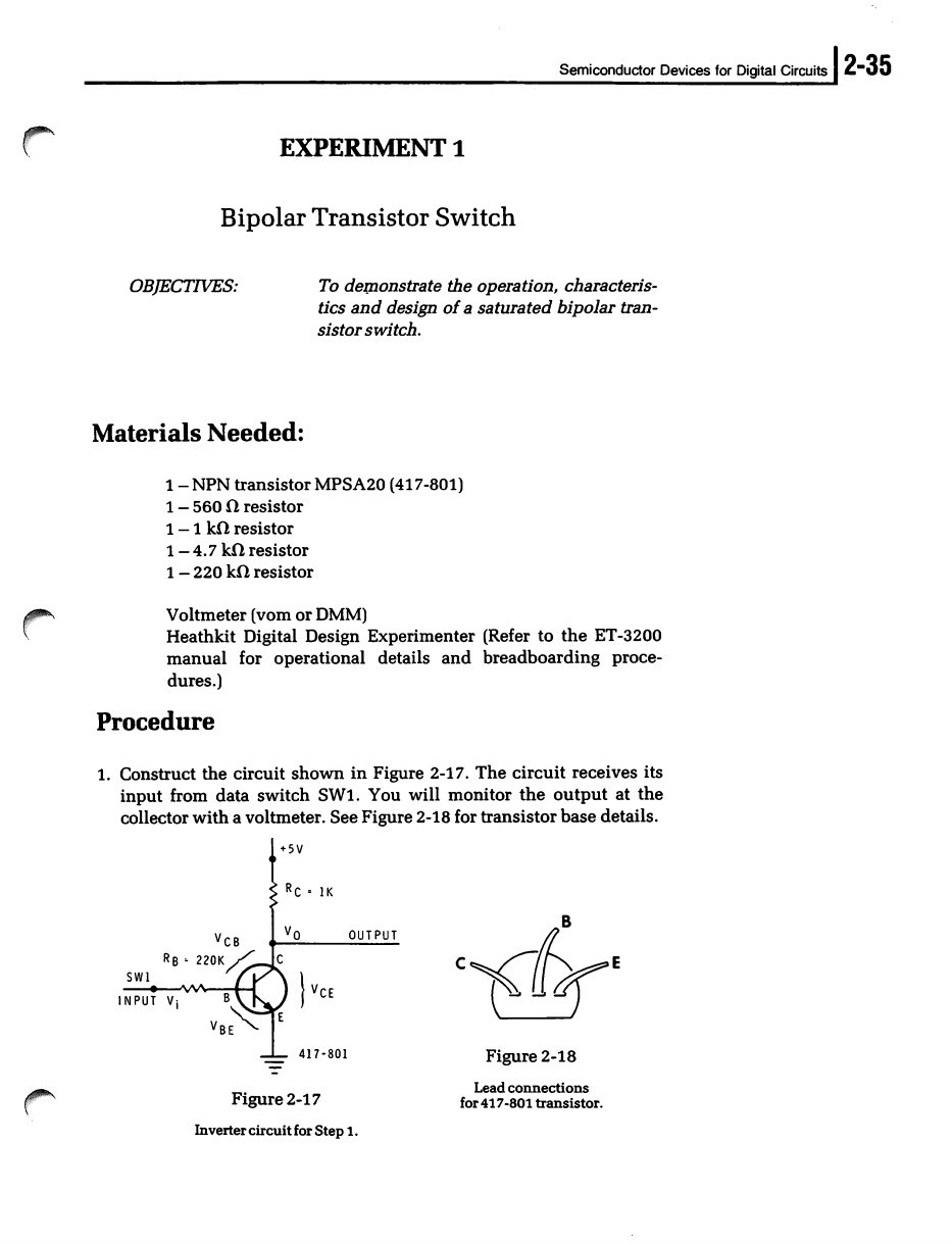
Experiment 1, Bipolar Transistor Switch. The student builds a one-transistor inverter from an MPSA20 (Heath 417-801) and a few resistors, and drives its base from data switch SW1. The text states the trainer’s part in the circuit: “The input logic signal will come from data switch SW1 and is +5 volts as seen through a 470 Ω resistor. (See Schematic of ET 3200 Digital Design Experimenter.)” The student measures junction voltages with a meter, decides whether the transistor is saturated, then designs a switch for a 560 Ω load on the +12 V supply. The worked answer includes the trainer’s internal 470 Ω resistor in the base calculation and suggests building the 17.4 kΩ result from “a 10 K ohm resistor in series with a 4.7 K ohm resistor … in breadboarding this circuit on your ET-3200” (EE-3201A, pp. 2-35 to 2-39). The trainer’s own internals are part of the lesson.
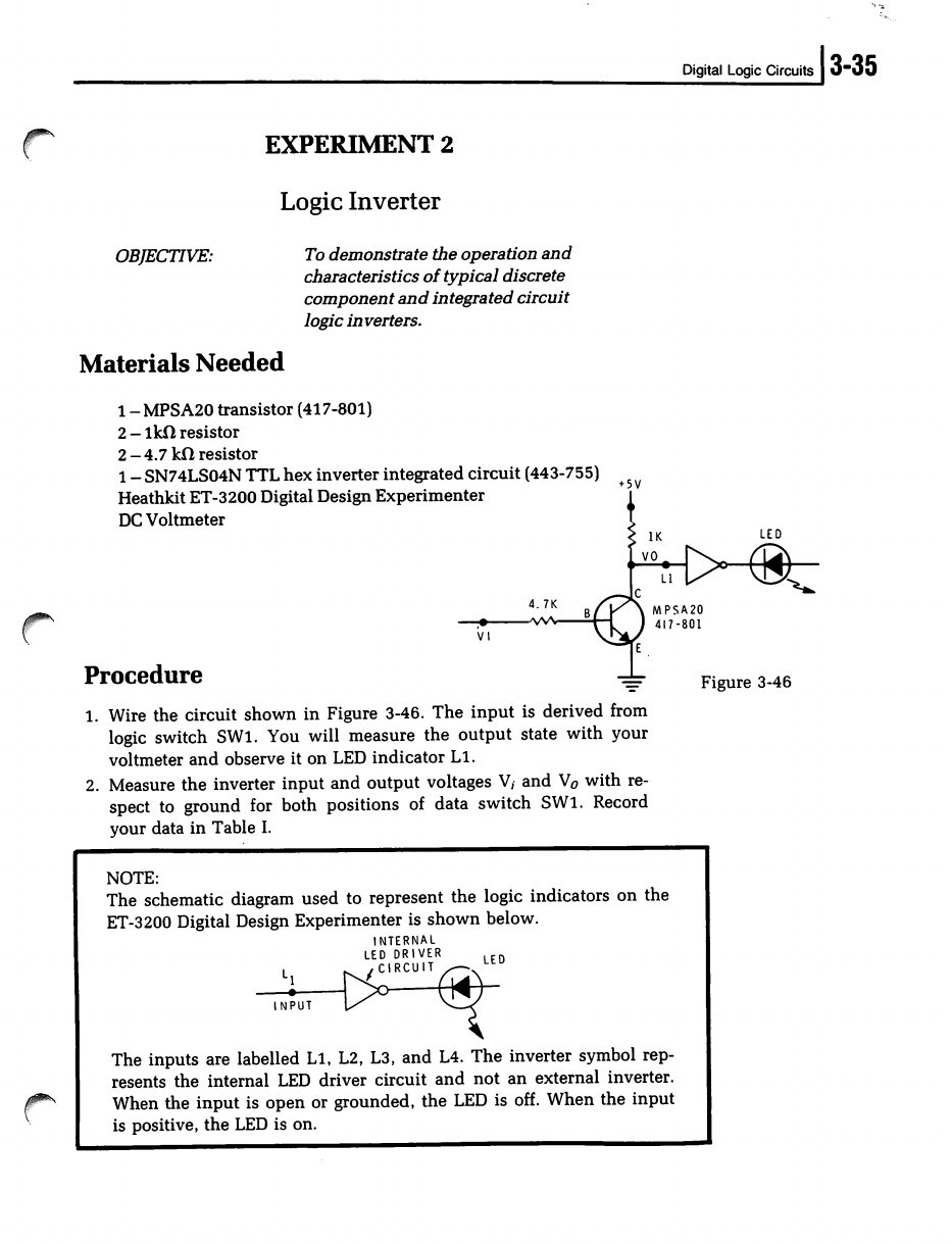
Experiment 2, Logic Inverter. The student builds the same inverter and watches it on indicator L1. The clock is then set to 1 Hz and connected to the input, with L2 on the input and L1 on the output, so the two LEDs alternate once a second. Two cascaded inverters follow, and then a 74LS04 hex inverter. The text explains how the ET-3200’s indicators are drawn in its diagrams. Each is shown as an input, an inverter symbol and an LED, and “the inverter symbol represents the internal LED driver circuit and not an external inverter. When the input is open or grounded, the LED is off.” For the IC, the student is told to “refer to the instruction manual of your ET-3200 Digital Design Experimenter for details on installing the IC on the breadboarding socket. The IC should straddle the center notch and all pins should be seated firmly” (EE-3201A, pp. 3-35 to 3-39).
The later experiments add the rest of the panel. The logic switches clock flip-flops and counters one clean step at a time, the one job where a data switch’s contact bounce would spoil the result. The 1 Hz clock runs counters and shift registers slowly enough to follow on four LEDs. The 1 kHz and 100 kHz settings drive the oscilloscope work. The line source is a known 60 Hz input for dividers and the counter applications. The ±12 V supplies serve the analog sides of the data-conversion experiments. There are only four indicators, and some experiments ask for more outputs than that; the student then moves indicators around or uses the meter.
4.7 The manual’s own example
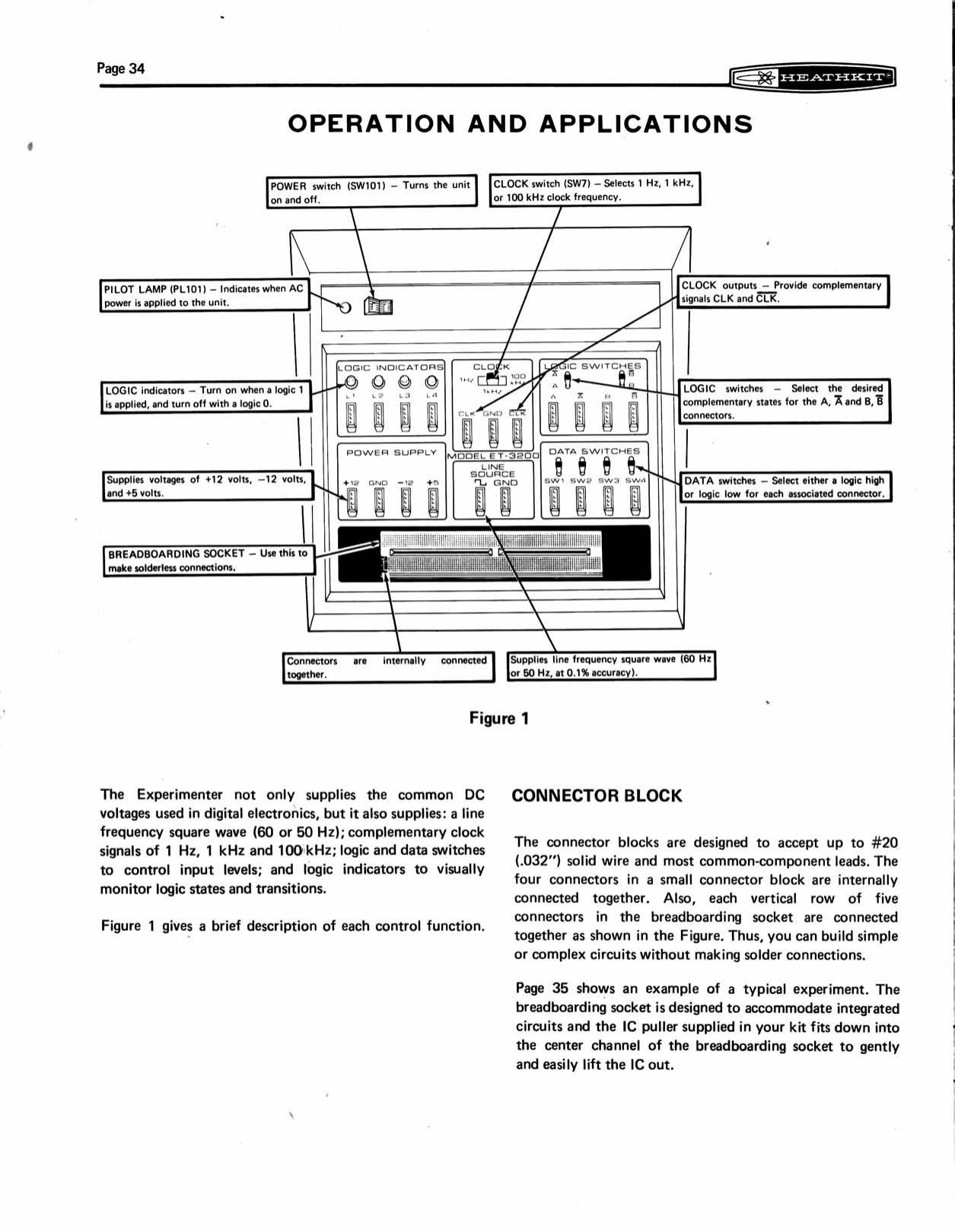
The trainer’s manual has its own short tutorial. Its “Operation and Applications” section explains each panel function on a labelled drawing (Figure 1), states that each small connector block’s four contacts “are internally connected together”, and that each vertical row of five breadboard contacts is common. It notes that the IC puller “fits down into the center channel of the breadboarding socket to gently and easily lift the IC out” (ET-3200 manual, p. 34).
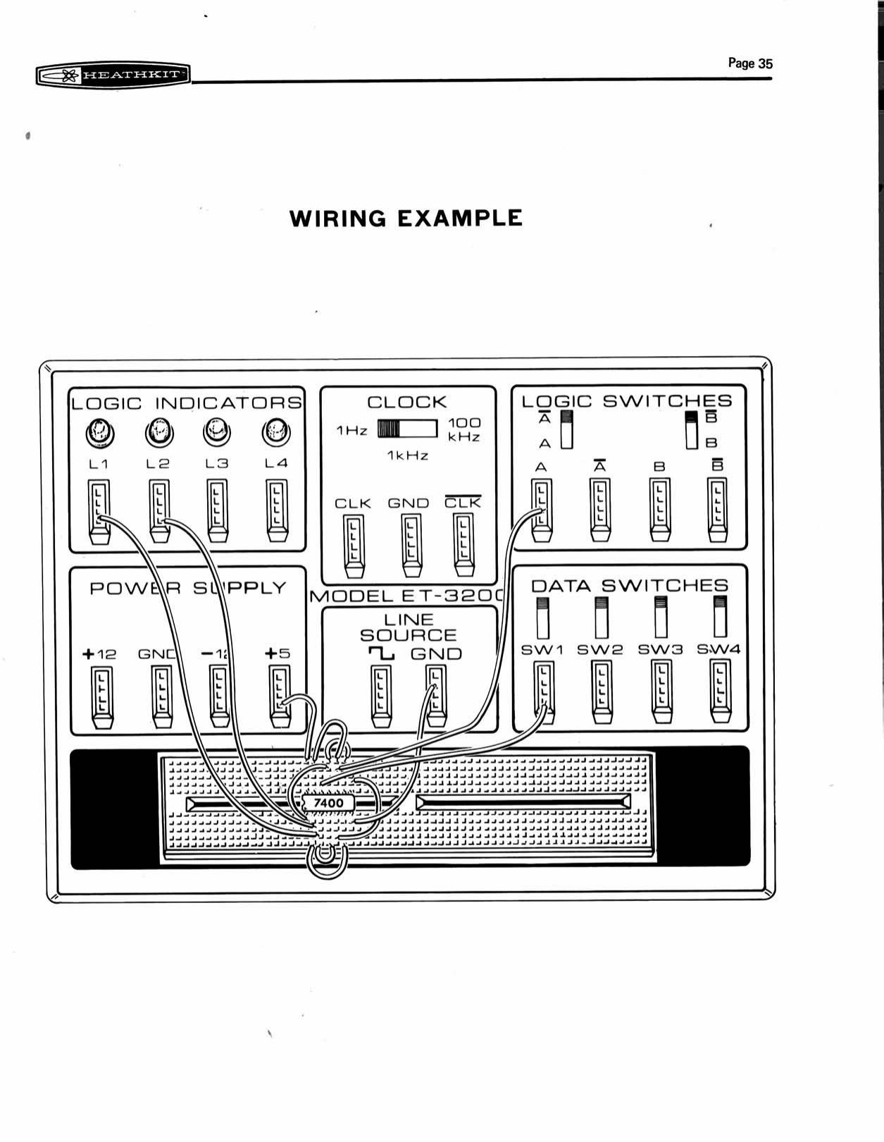
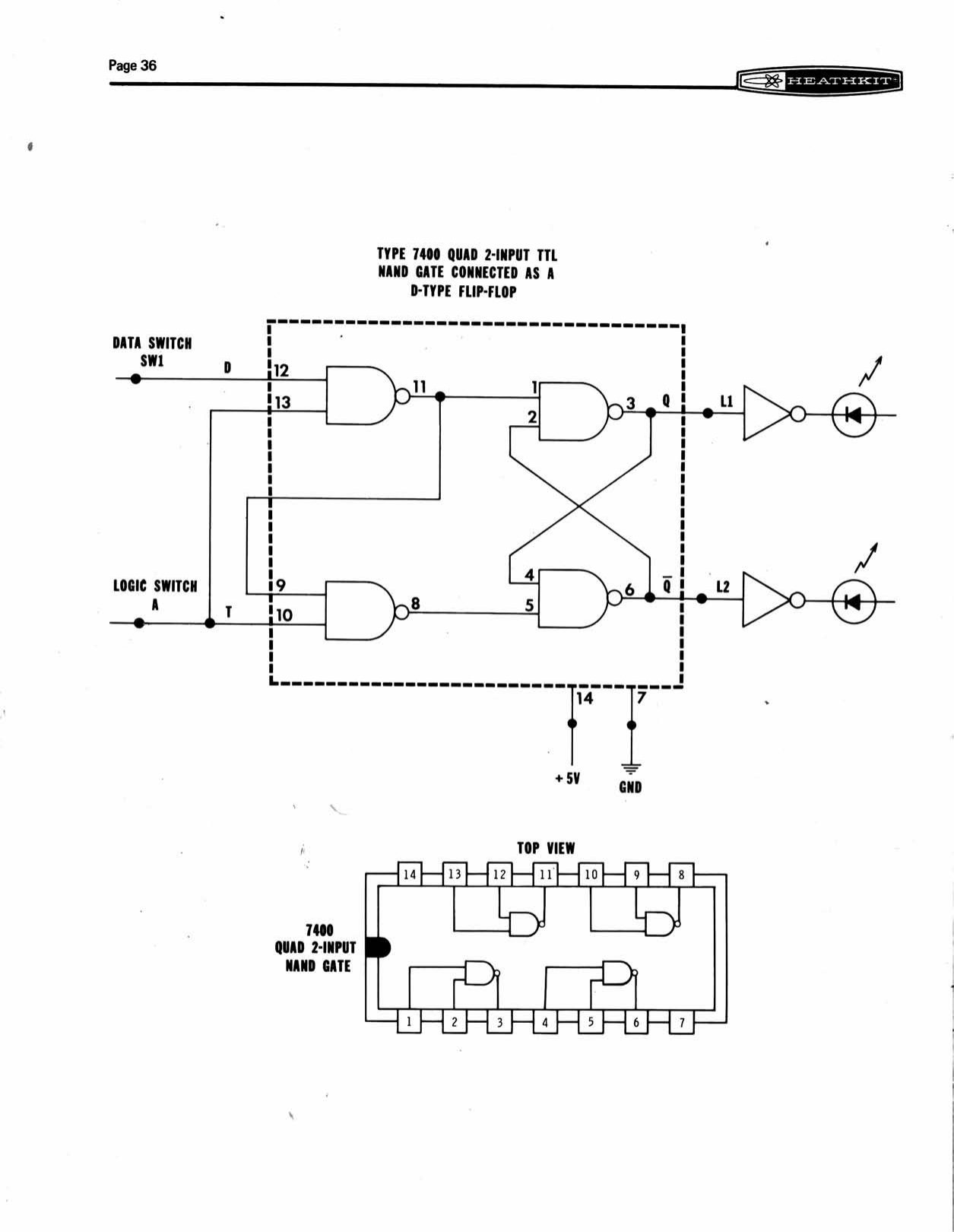
A two-page Wiring Example follows: a 7400 quad NAND “connected as a D-type flip-flop”, with data switch SW1 as the D input, logic switch A as the clock, and indicators L1 and L2 on the Q and Q̄ outputs. The first page shows every jumper on a drawing of the panel. The second gives the logic diagram and the 7400’s pinout. Strictly, the circuit drawn is a gated D latch, transparent while the clock input is high, not an edge-triggered flip-flop. It is the classic four-NAND latch of the textbooks of the period, and it uses every kind of panel function except the clock.
4.8 After the course: the trainer on the bench
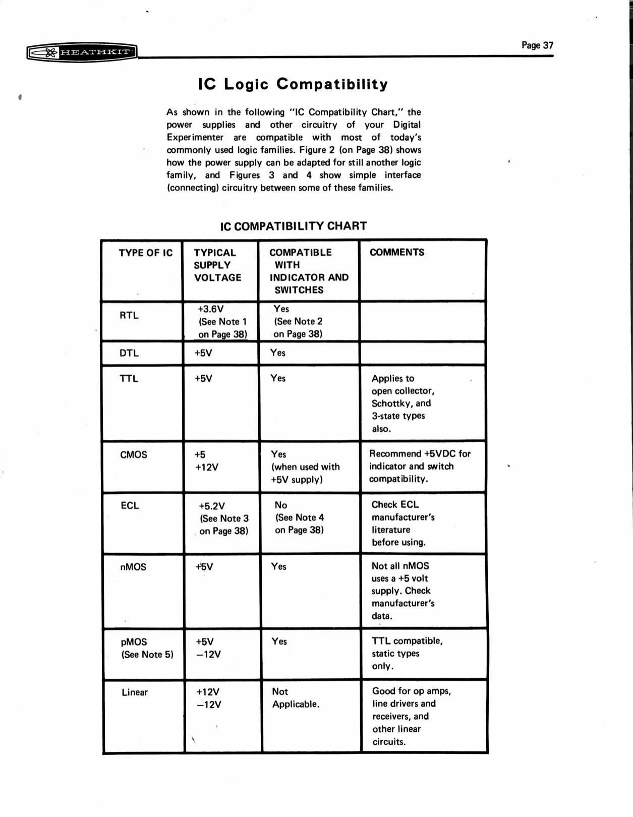
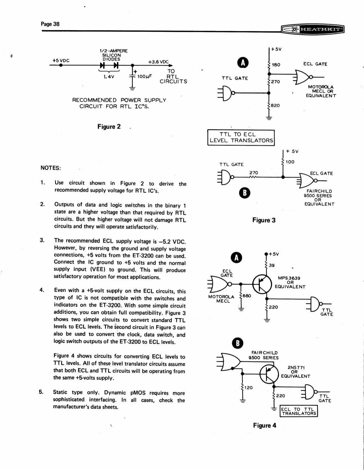
Every catalogue description promised a second life for the trainer, and the manual’s compatibility pages were written for that user. The IC Compatibility Chart covers RTL, DTL, TTL (including open-collector, Schottky and three-state types), CMOS, ECL, nMOS, pMOS and linear circuits, with a typical supply voltage for each and whether the trainer’s switches and indicators can be used directly. Three circuits cover the awkward cases. Figure 2 makes a +3.6 V RTL supply from the +5 V rail with two diodes. Figures 3 and 4 give level translators between TTL and ECL, using an MPS3639 or 2N5771 transistor and Fairchild 9500-series or Motorola MECL gates, all powered from the same +5 V supply (manual, pp. 37–38).
For linear work the ±12 V supplies, current-limited at about 130 mA, suit op-amps and comparators, and the chart calls them “good for op amps, line drivers and receivers”. The line source is a stable low-frequency reference. For more breadboard space than the ET-3200 offered, Heath sold the ET-3300 laboratory breadboard from 1976. It had four breadboarding sockets, “three dual ground and power bus strips”, and its own supplies, and was aimed at “hobbyists and technicians in laboratory experiments” and “designers for building up a prototype” (Spring 1976 catalogue, p. 68).
4.9 The trainer’s place in the curriculum
The course sequence explains why the ET-3200 looks the way it does. A student following the full curriculum built the ET-3100 first and used it through DC, AC, semiconductors and circuits. That trainer has variable supplies, a signal generator and potentiometers, because those courses are about measuring analog quantities. Digital Techniques assumed those courses “or equivalent knowledge” and changed the question from “how much?” to “which state?”. The second trainer therefore has fixed supplies, switches and lamps. The ET-3200 has no signal generator, no variable supply and no meter. The course expected the student to own a VOM, and later an oscilloscope, which Heath also sold. Microprocessors came next, from Christmas 1977, with the ET-3400. That trainer built the ET-3200’s switches, indicators and supplies into a small computer, as described in volume 5.
The same Christmas 1982 page sums up the design aim: “Put your digital knowledge to work with the high-quality ET-3200A Electronic Trainer … This versatile trainer also allows you to build and test prototypes, confirm circuit operation, and test digital ICs” (Christmas 1982, p. 35).
Sources
- Frenzel, Lou. “The History of Personal Computers, Part 2: The Heathkit Story.” Electronic Design, 30 December 2013. https://www.electronicdesign.com/technologies/communications/article/21799215/the-history-of-personal-computers-part-2-the-heathkit-story
- Heathkit catalogues: Christmas 1975, Spring 1976, Fall 1977, Spring 1978, Fall 1979, Winter 1981, Winter 1981–82, Christmas 1982, Fall 1985. World Radio History. https://www.worldradiohistory.com/Archive-Catalogs/Heathkit_Catalogs.htm
- Heathkit/Zenith Educational Systems & Instruments catalogue 811-29R. https://www.worldradiohistory.com/Archive-Catalogs/Heathkit-Catalogs/Heathkit-1975-Zenith%20Educational%20Systems-811-29R.pdf
- Heathkit Company, Inc. Digital Techniques, Model EE-3201A, 595-2931-09, © 1983, 1993, 1998. https://archive.org/details/ee-3201-a-digital-techniques-individual-learning-system-textbook-1998
- Heath Company. Heathkit Manual for the Digital Design Experimenter, Model ET-3200, 595-1740-03, © 1975. https://archive.org/details/Heathkit_ET-3200_Digital_Design_Experimenter
- Heathkit history dive, volume 7, “After the Kits.” https://heathkit.fubsypoly.com/heathkit/vol-7/
Comments (0)