HW-101 Transceiver · Volume 4
Alignment and Use
A finished HW-101 is not a working HW-101. Every tuned circuit in it — eight heterodyne oscillator coils, three IF transformers, five pairs of driver coils, the VFO, the carrier isolation transformer, two neutralising adjustments and a carrier null — leaves the factory in a bag of parts and arrives at its correct setting only because the builder puts it there. The alignment section occupies seven pages of the manual and is the last real piece of construction, not a formality after it.
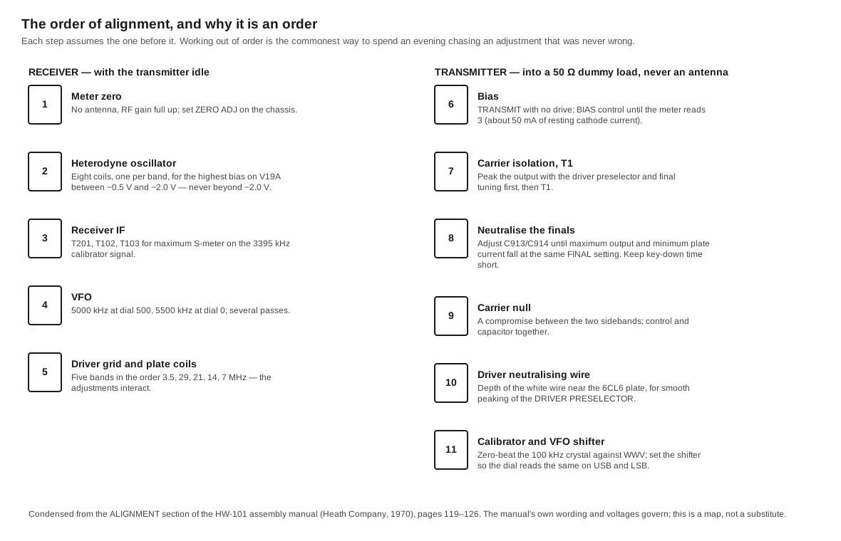
It is also the section most often done badly, because the steps interact and the order is not obvious. What follows is a map of the procedure and of the reasoning behind it, not a substitute for the manual, whose own wording and voltages govern.
4.1 Before any of it: the voltages inside
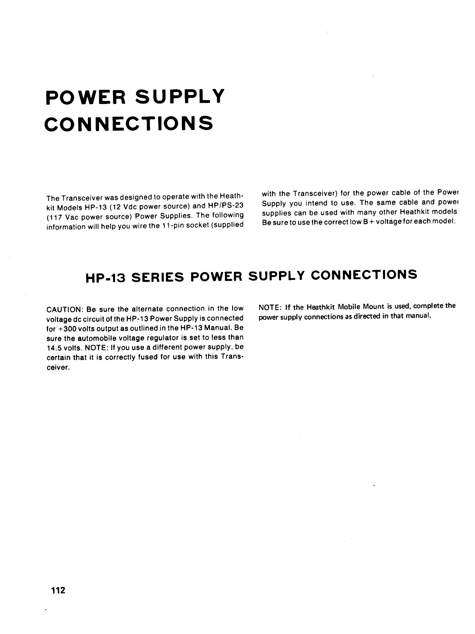
The HW-101 runs 700 to 850 volts on the finals, and the manual’s second page is a full-page red warning to that effect. Two habits matter more than any other safety advice. The first is that the power supply must be switched off and the power cable removed before any test involving contact with the chassis, and — as the manual puts it — “as additional insurance against shock, a screwdriver blade should be used to short from the chassis to the red B+ wires”, because the supply’s filter capacitors hold their charge after the mains is gone. The second is that alignment is done into a 50 Ω dummy load, not an antenna and not a light bulb, and that full output is not left on: the manual’s own caution is not to run full output continuously for more than thirty seconds at a time and to let the tubes cool for at least a minute afterwards.
4.2 The equipment
Heath’s list is short because the rig contains most of its own test equipment: the 100 kHz crystal calibrator supplies the signal for receiver alignment, and the front-panel meter reads the result. The remainder is a 50 Ω dummy load — Heath sold the HN-31 “Cantenna” for exactly this — a high-impedance voltmeter of 11 MΩ or better, an RF wattmeter or SWR bridge, a set of non-metallic alignment tools for the coil slugs, and, optionally, a frequency counter to set the VFO endpoints without iterating against the calibrator.
4.3 Receiver alignment
Meter zero first. With no antenna and the RF gain full clockwise, the ZERO ADJ control on the chassis is set so the meter reads zero on the S-meter scale. Everything that follows is read on that meter, so a meter that is not zeroed produces alignment errors in every later step.
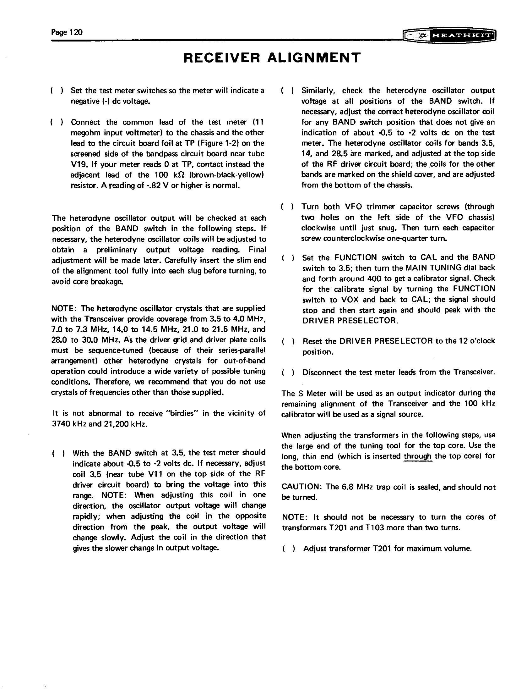
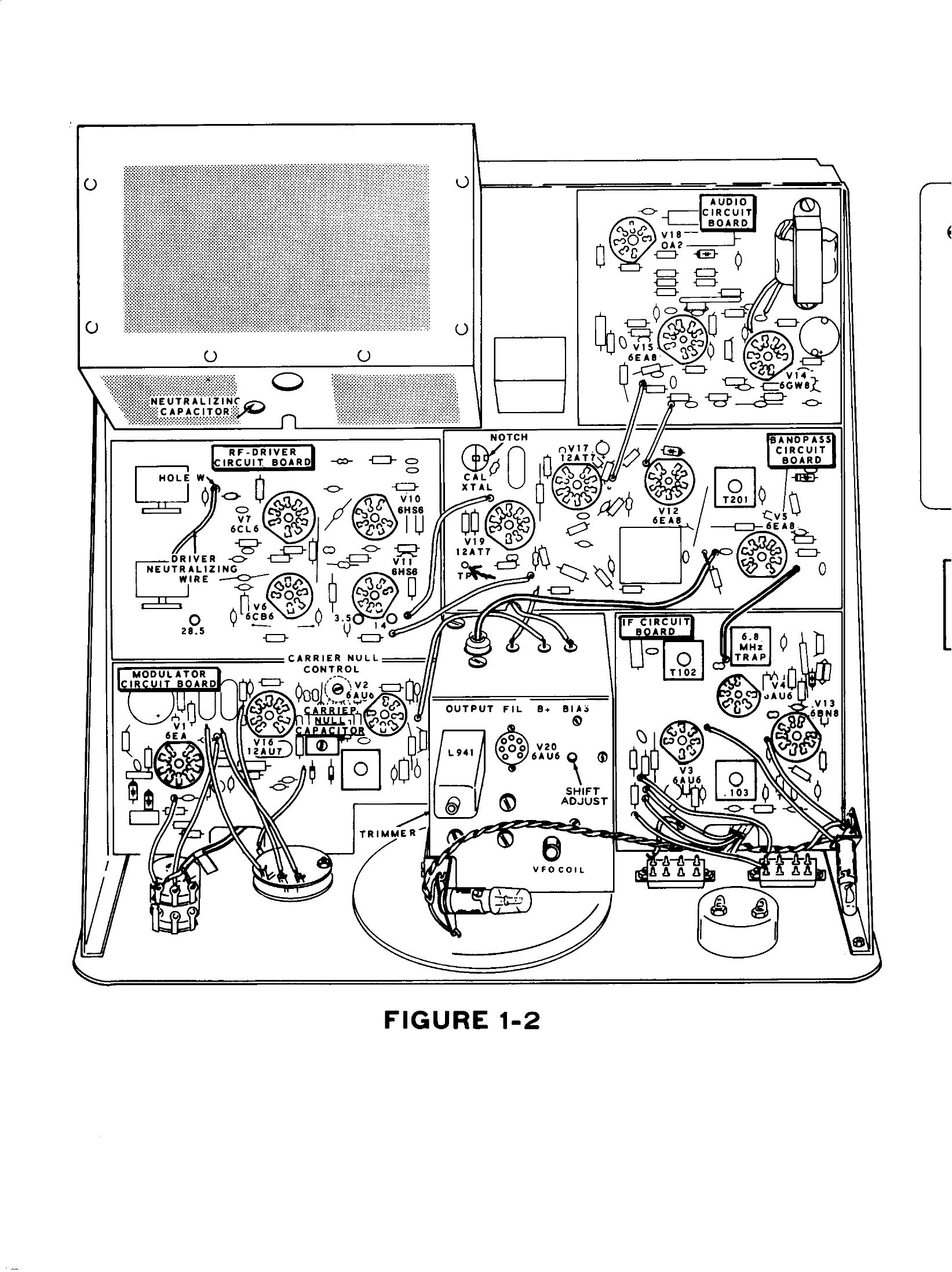
The heterodyne oscillator. Eight coils, L601 to L608, one per band segment, each adjusted for the highest negative bias measured at the grid of V19A through the test point on the chassis — and the manual is specific that the reading should be as high as possible between −0.5 and −2.0 volts but must not exceed −2.0 volts. Five of the coils are reached from the chassis bottom and three from the top of the RF-driver board. An oscillator that is not oscillating, or is oscillating on the wrong overtone, makes its band completely dead; a bias reading at the test point is the quickest diagnosis there is.
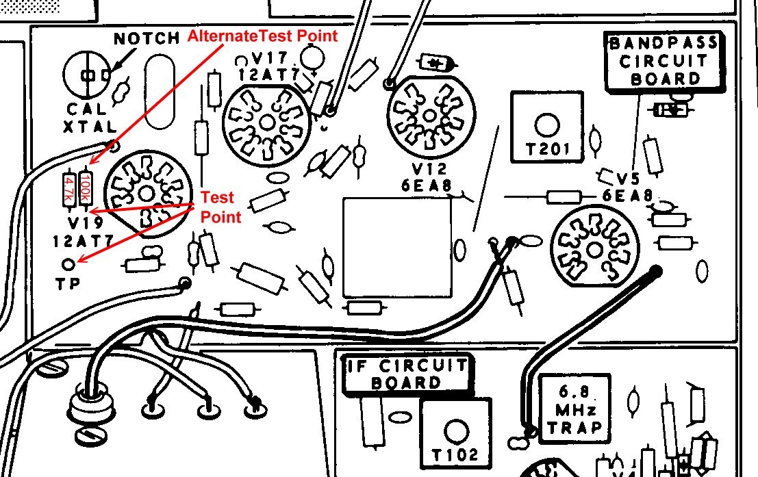
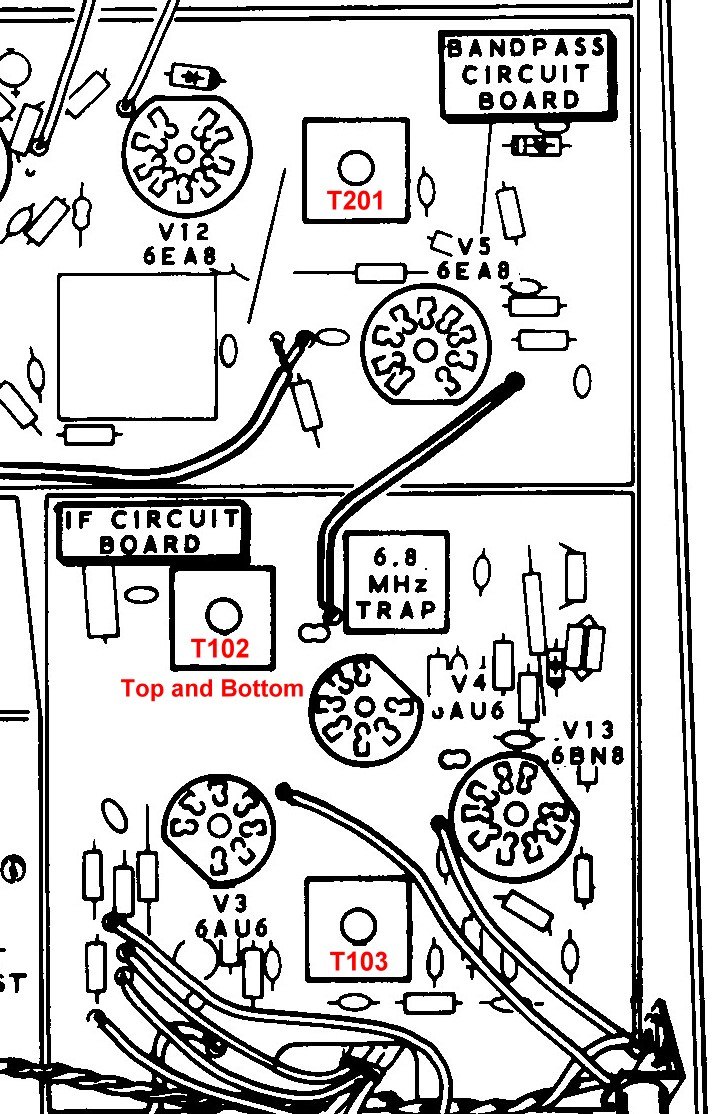
The receiver IF. Three transformers — T201 on the bandpass board, T102 and T103 on the IF board — are peaked for maximum S-meter reading on a calibrator signal at the 3.395 MHz intermediate frequency. The crystal filter itself has no adjustment; what is being set is the tuning of the amplifiers either side of it.
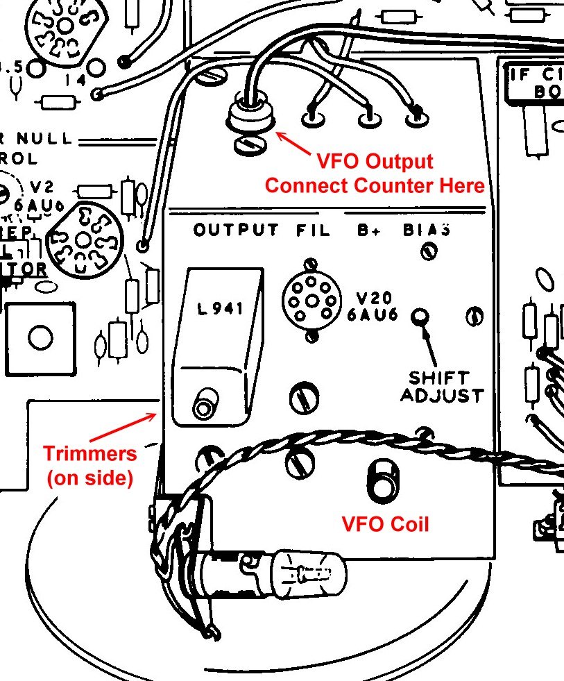
The VFO. The oscillator must read 5000 kHz with the dial at 500 and 5500 kHz with the dial at 0, which takes several passes because the coil slug and the trimmer capacitor each affect both ends. With a counter the job is mechanical; without one it is done against the calibrator, checking 100 kHz points across the dial. The manual insists on at least thirty minutes of warm-up first, and the specification’s promise of 100 Hz per hour assumes forty-five.
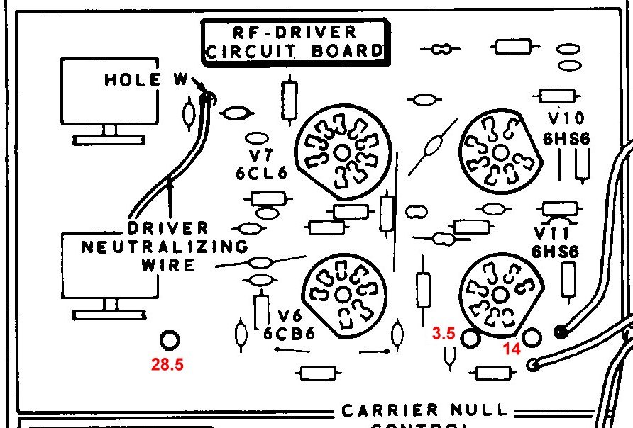
The driver grid and plate coils. Five pairs, adjusted in the order 3.5, 29, 21, 14 and 7 MHz — an order that looks arbitrary and is not. Each band’s coil is paralleled with the others by the band switch, so adjusting one changes the others; Heath’s sequence is chosen so that the interactions converge instead of chasing each other. These are the circuits tuned by the DRIVER PRESELECTOR, and they serve the receiver’s front end and the transmitter’s driver at the same time, which is why they are aligned as part of receiver alignment and then checked again from the transmitter side.
4.4 Transmitter alignment
Bias. In transmit with no drive, the BIAS control is set until the meter reads 3 on the plate-current scale — 50 mA of resting cathode current for the pair of 6146s. Too little bias and the finals run hot and distort; too much and the amplifier is no longer linear.
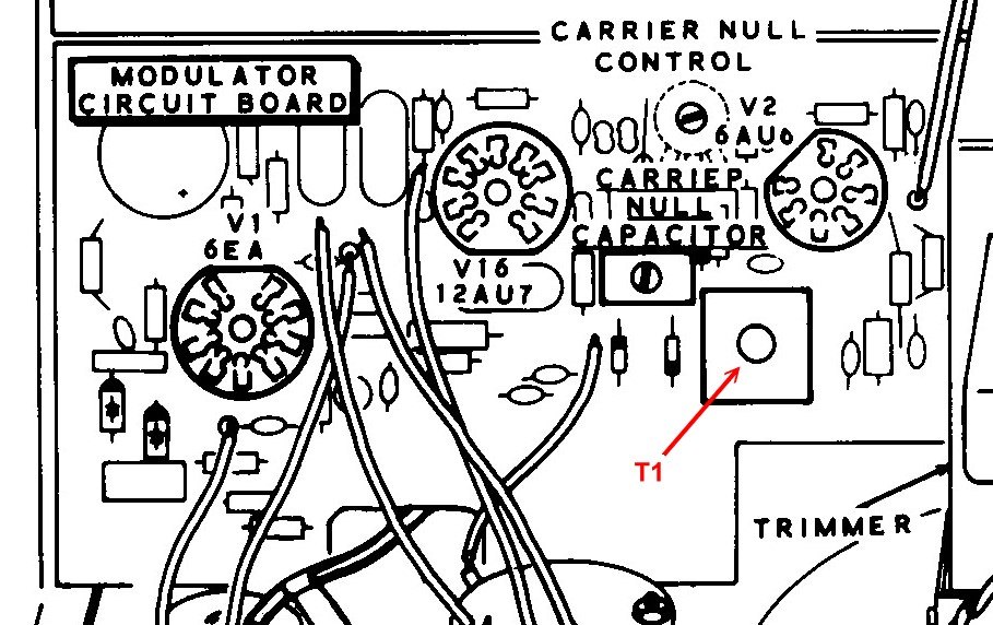
Carrier isolation transformer T1. Drive is brought up to a small indication, the DRIVER PRESELECTOR and FINAL TUNE are peaked, and then T1 at the balanced modulator’s output is adjusted for maximum RF output.
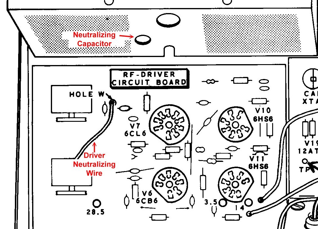
Neutralising the finals. This is the adjustment the manual singles out as one of the most important in the set, and the criterion is a coincidence rather than a maximum: the neutralising capacitors are set so that maximum RF output and minimum plate current occur at the same setting of the FINAL TUNE control. If they occur at different settings, the stage is regenerative, and a regenerative final amplifier is an oscillator waiting for an excuse. The manual repeats the test as a standing rule for the owner: any time the final tubes are changed, tune up, then switch the meter between REL PWR and PLATE, and if the power peak and the current dip do not coincide, do not operate the transmitter until it has been re-neutralised.
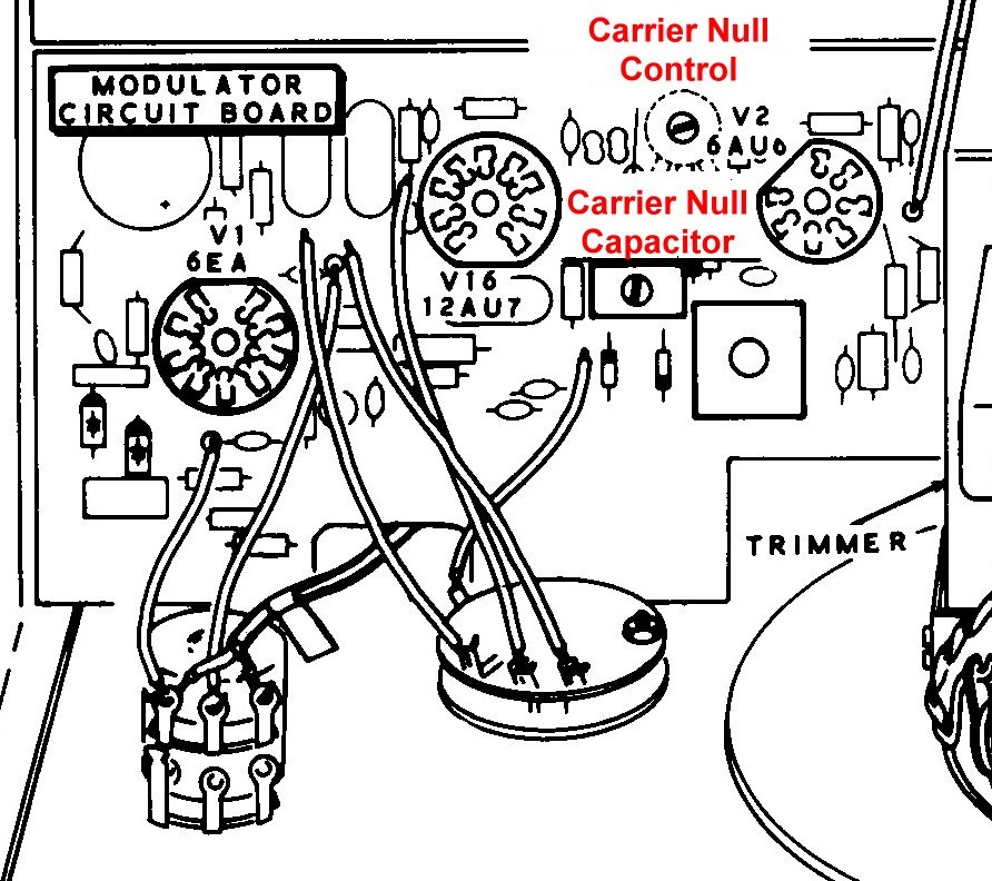
Carrier null. The control and its trimmer capacitor together null the carrier at the balanced modulator, and the setting is necessarily a compromise between the two sidebands, since the carrier crystal frequency differs between them. A rig that cannot be nulled has usually lost the control itself — see the restoration volume — rather than gone out of adjustment.
The driver neutralising wire. The 6CL6’s neutralisation is adjusted by changing how far a length of insulated wire is pushed past the tube’s plate, altering a few picofarads of coupling. The test is that the DRIVER PRESELECTOR peaks smoothly rather than jumping or showing two peaks.
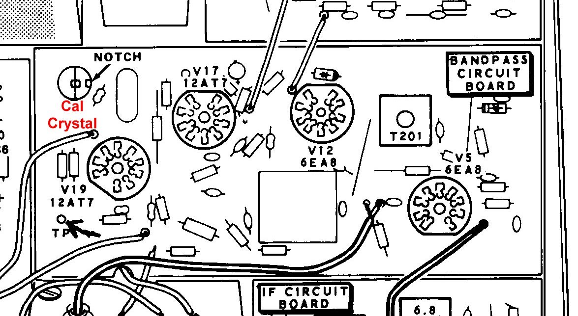
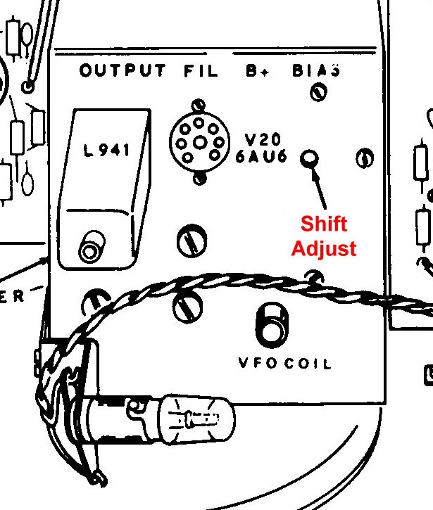
Calibrator and VFO shifter. The 100 kHz crystal is set by zero-beating one of its harmonics against WWV on 10 or 15 MHz using a second receiver. The VFO SHIFTER trimmer on top of the VFO box is then set so that the dial reads the same frequency on upper and lower sideband — the adjustment that compensates for the 2.8 kHz difference between the two carrier crystals.
4.5 The controls
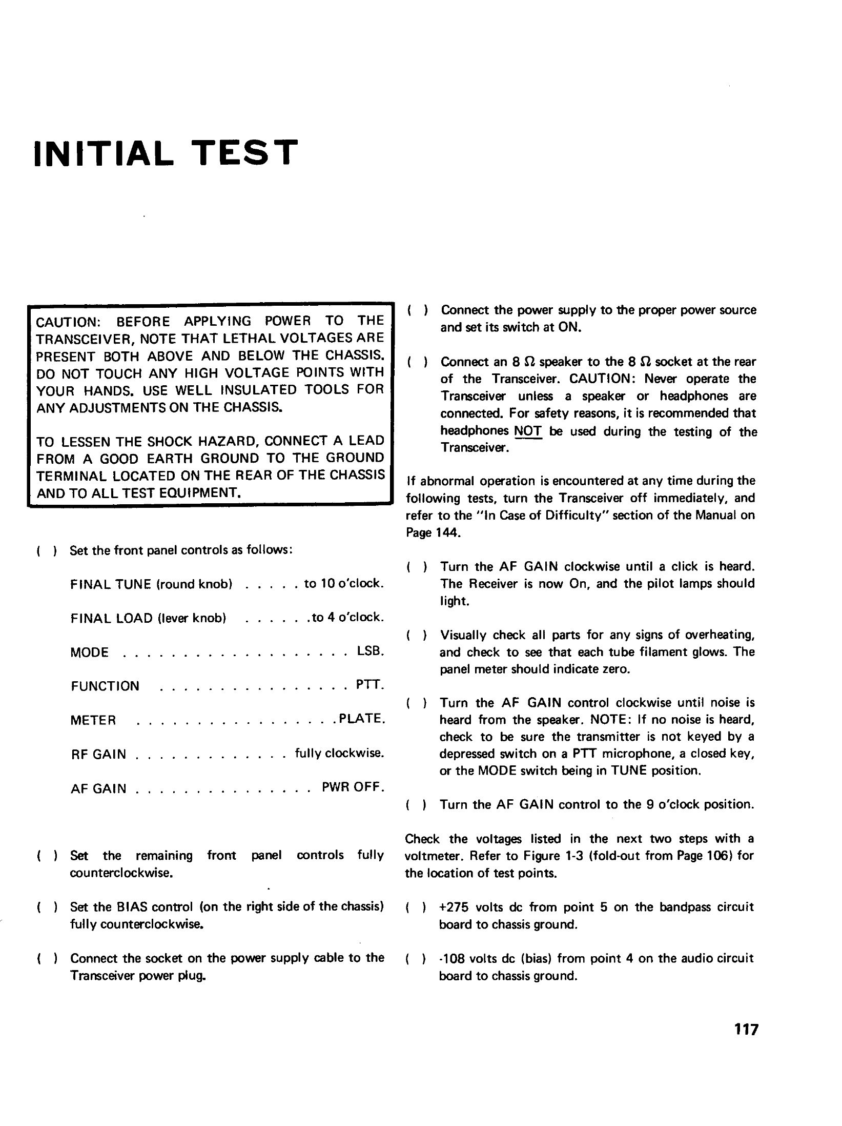
The HW-101’s panel has no hidden modes and nothing that is not what it says. Reading it from the left: DRIVER PRESELECTOR, FINAL TUNE and FINAL LOAD across the top; MIC/CW LEVEL, RF GAIN and AF GAIN below them with the microphone connector and headphone jack; the main tuning dial in the centre behind its window; and on the right the FUNCTION switch (PTT, VOX, CAL), the MODE switch (LSB, USB, CW, TUNE), the BAND switch, the METER switch (ALC, PLATE, REL PWR) and the meter itself. Two slide switches handle SSB/CW filter selection and power.
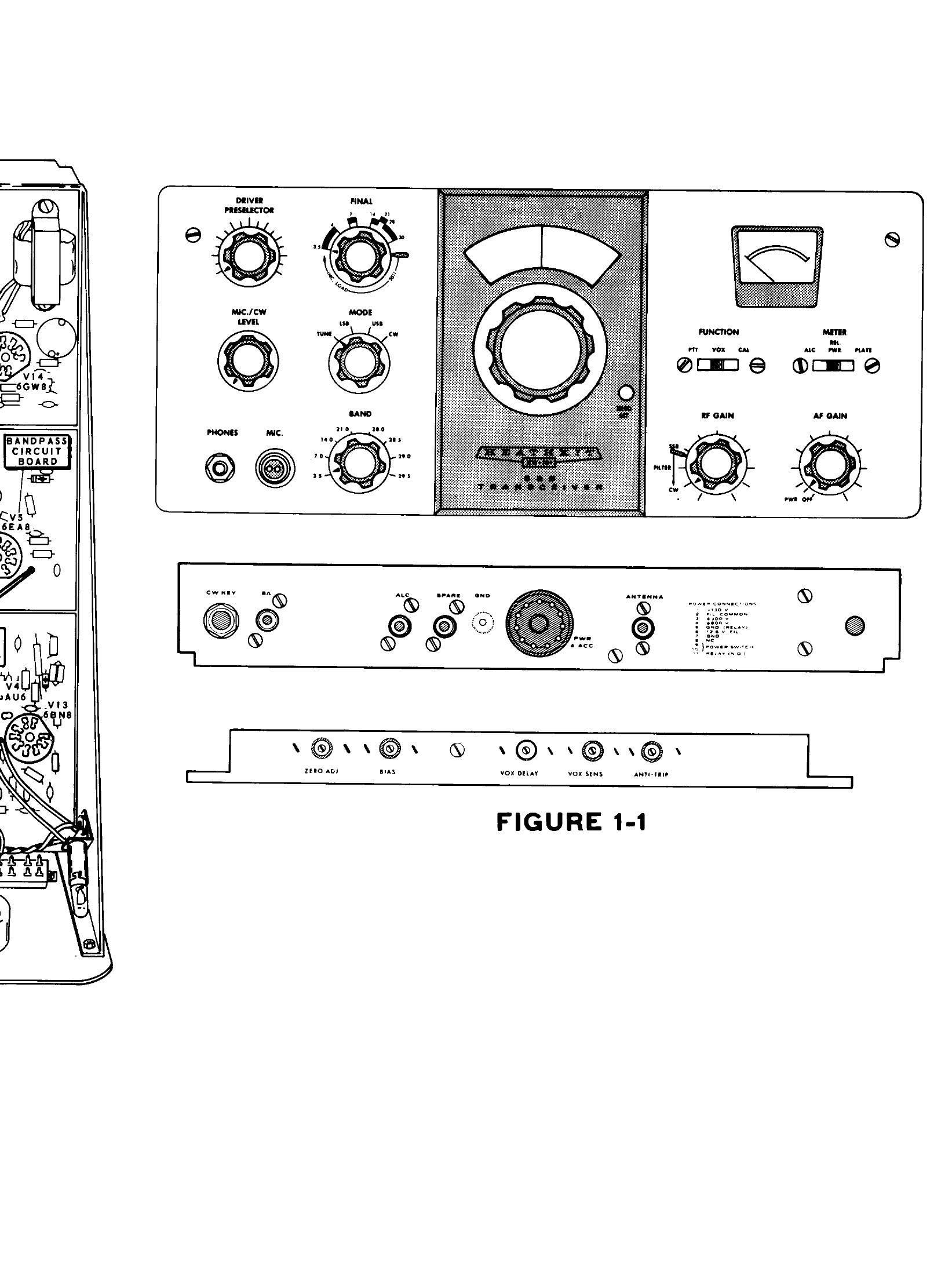
Five more controls live on the right-hand side of the chassis, reachable with a screwdriver through the cabinet: METER ZERO, BIAS ADJUST, VOX SENSITIVITY, VOX DELAY and ANTI-TRIP. The internal adjustments — carrier null, neutralising, calibrator trimmer, VFO trimmer, VFO shifter and VFO coil — are alignment settings and are not touched in ordinary use.
4.6 Reading the meter
One meter, four readings, and the scale is not marked in engineering units, which catches out every new owner. In the PLATE position each numbered figure on the scale represents 50 mA of final cathode current, so a reading of 9 is 150 mA and full scale at 60 is 300 mA. In REL PWR the meter shows relative output from a diode sampling the antenna line — useful for peaking, meaningless as an absolute. In ALC it reads the compression being applied to the speech. And in receive, with the switch at ALC, the same needle becomes the S-meter.
4.7 Finding a frequency
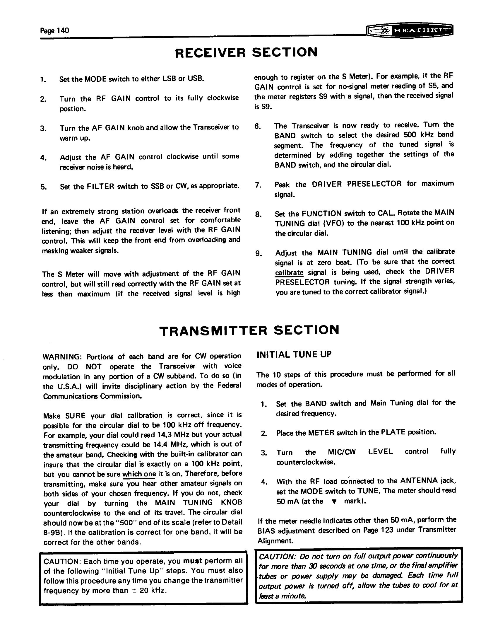
There is no digital readout, so the operating frequency is the band-switch setting plus the circular dial reading: the switch selects a 500 kHz segment, the dial reads the 500 kHz within it, five kilohertz per division, 35⅓ turns of the knob from one end to the other. The manual is careful to warn that the dial can be a whole 100 kHz out and still track correctly, so a dial that reads 14.3 MHz might be transmitting on 14.4 — outside the band. The cure is the built-in calibrator: switch FUNCTION to CAL, set the dial to the nearest 100 kHz point, and adjust until the calibrator signal zero-beats. A useful check is included in the same step: vary the DRIVER PRESELECTOR, and if the calibrator signal’s strength changes, it is the right one.
4.8 Tuning up
The tune-up is a ten-step ritual that has to be performed whenever the band is changed, whenever the finals are changed, and whenever the frequency moves by more than about 20 kHz.
- Set the band switch and the dial to the operating frequency.
- Meter to PLATE.
- MIC/CW LEVEL fully counter-clockwise.
- With the load connected, MODE to TUNE. The meter should read 50 mA — the mark at 3. If it does not, the bias adjustment is wrong and is set first.
- Meter to REL PWR; loading lever to the four o’clock position.
- FINAL TUNE to the position marked for the band in use.
- Bring up MIC/CW LEVEL for a small upscale reading, then peak the DRIVER PRESELECTOR, FINAL TUNE and LOAD alternately for maximum.
- Increase MIC/CW LEVEL until the meter stops rising with knob rotation, and re-peak.
- Meter to PLATE: the needle should read about 40 on the scale, which is 250 mA of plate current.
- Return MIC/CW LEVEL to zero.
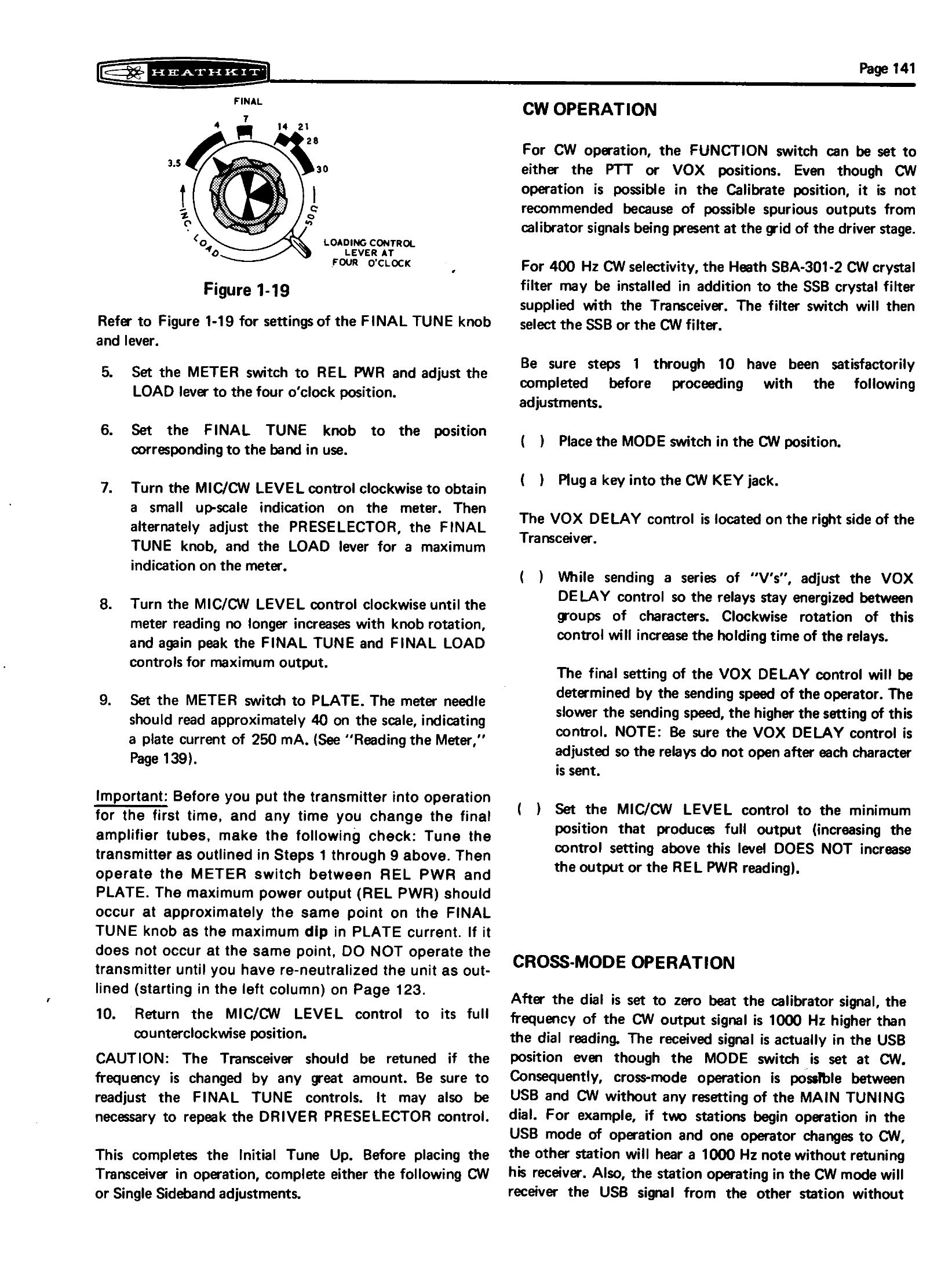
For SSB the MIC LEVEL is then set by speaking normally and watching the ALC indication; for CW the MIC/CW LEVEL is set to the minimum position that produces full output, since turning it higher adds nothing.
4.9 On the air
Sideband. Lower sideband on 80 and 40 metres, upper on 20, 15 and 10, by the convention that was already settled when the rig was designed. PTT or VOX, selected by the function switch; VOX SENSITIVITY, VOX DELAY and ANTI-TRIP set from the side of the chassis by ear, with the delay long enough to hold through the pauses in ordinary speech and the anti-trip just high enough that the loudspeaker cannot key the transmitter.
CW. The key plugs into the rear apron; the mode switch goes to CW; and keying starts the transmitter through the VOX circuit using the internal 1000 Hz tone, so the VOX DELAY control becomes the break-in speed control. Heath’s instruction is to send a series of Vs and set the delay so the relays stay energised between characters but drop out between transmissions — a setting that depends on the operator’s sending speed. The 400 Hz SBA-301-2 filter, if fitted, is selected with the filter switch.
There is one consequence of the CW carrier offset that owners need to know and that the manual explains carefully. The transmitted CW signal is 1000 Hz higher than the dial reading, and a CW signal is actually received in the USB position. Cross-mode operation therefore works without retuning: if two stations are working USB and one switches to CW, the other hears a 1000 Hz note without touching the dial.
What it cannot do. There is no receiver incremental tuning, so working a station that is slightly off frequency means moving the transmitter too; netting is done by ear on the calibrator and by courtesy. There is no QSK break-in beyond what the VOX delay allows. And the dial must be re-checked against the calibrator after the set has warmed, because the specified 100 Hz per hour is measured after forty-five minutes, not from switch-on.
Mobile. With the HP-13 series inverter and the SBA-100-1 bracket the rig runs from a car’s electrical system. The manual carries a separate mobile installation section and a separate mobile operating section, and warns about the obvious: the inverter draws heavy current, the mounting must be solid, and the final amplifier still wants a proper load.
Sources
- Heathkit Assembly Manual for the HW-101 SSB Transceiver, part 595-1277-18 (Heath Company, 1970): “Control and Connector Functions” pp. 101–104, “Initial Test” pp. 117–118, “Alignment” pp. 119–125, “Operation” pp. 139–143. Internet Archive
- Harris, Bill. “Heathkit HW-101 Alignment” — a worked account of the procedure on a restored unit, with photographs of every adjustment location. Link
- Cadman, Phil (G4JCP). “It’s a Classic! The Heathkit HW101.” Practical Wireless, November 2007, on the missing RIT control and on operating the rig today. Scan
Comments (0)