SB-102 Transceiver · Volume 3
Building the Kit
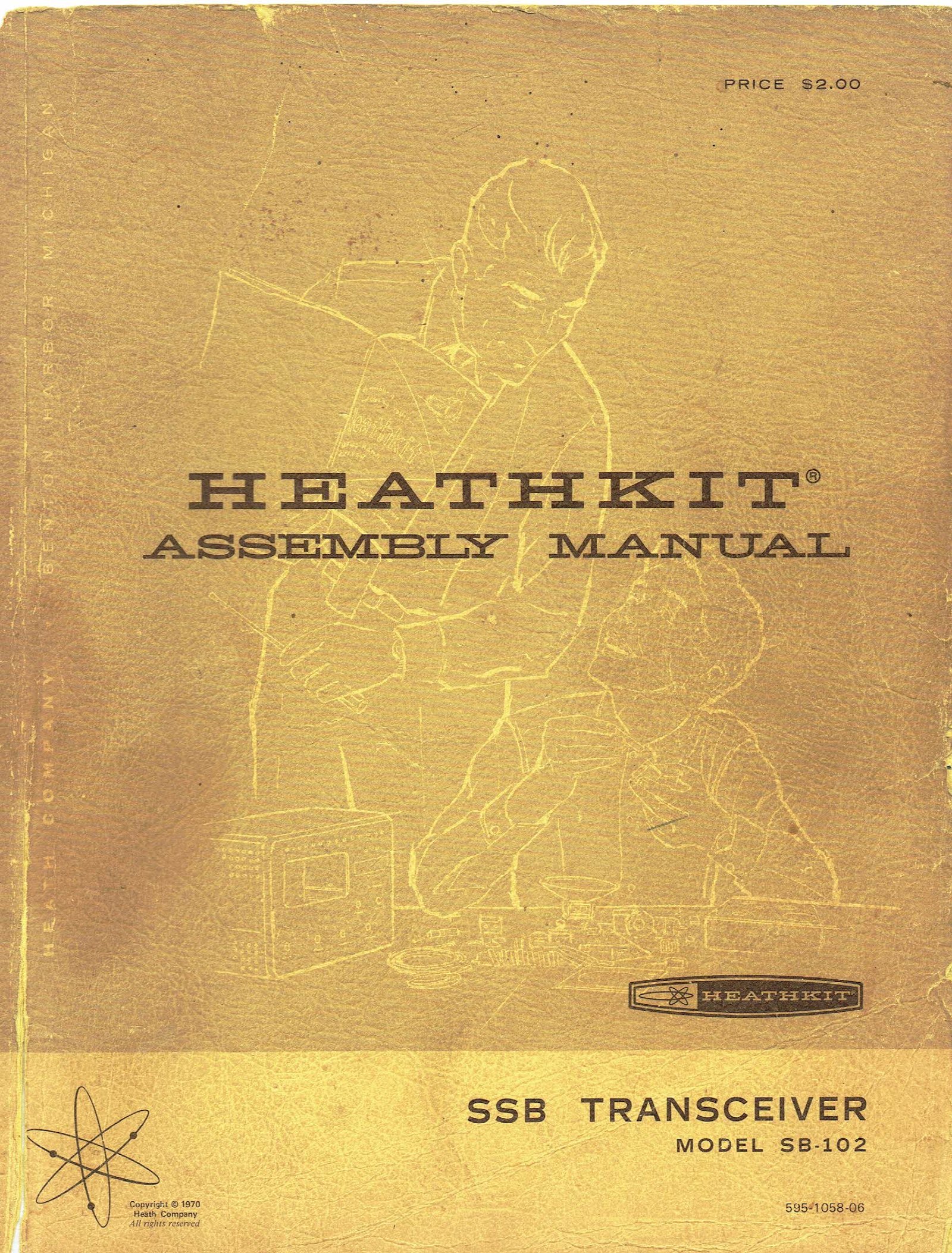
The SB-102 arrived as a carton of numbered parts packages, a punched and painted chassis, a front panel, a cabinet with a hinged lid, two pre-formed harnesses (one of wires, one of miniature coaxial cables), twenty tubes, a sealed LMO in its own box, and an assembly manual priced at $2.00 on its cover. The manual runs to 165 numbered pages plus a dozen fold-outs; the full scan used here has 214 pages. Its method is the one the site history dive describes in How a Heathkit Manual Works: parts identified against drawings rather than colour codes, every step a checkbox, and nothing powered until it has been checked with an ohmmeter.
Most of that experience is shared with the HW-101, and its dive’s build volume covers the common ground: the switch-boards, the circuit boards, the harness and the final cage. This volume follows the SB-102 manual in order and dwells on what the SB-102 builder did that the HW-101 builder did not. The main differences are the sealed LMO, which the builder mounted and aligned to the chassis but never opened, and the SB dial mechanism, which the builder assembled and calibrated from loose parts.
3.1 How the manual is organised
Table 1 — How the manual is organised
| Section | Manual pages |
|---|---|
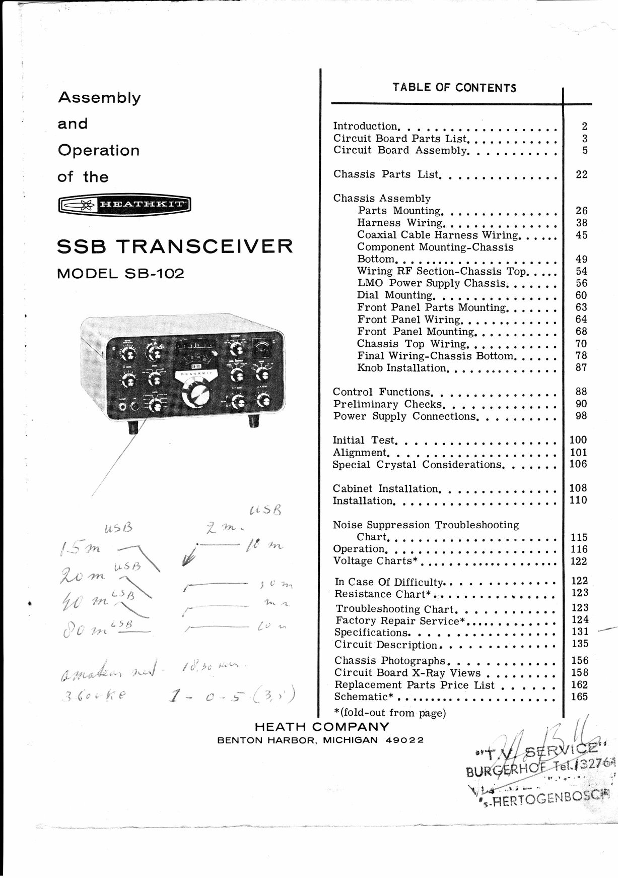
| Introduction; circuit board parts list | 2–4 |
| Circuit board assembly: four switch-boards, modulator, IF, bandpass, audio, RF driver | 5–21 |
| Chassis parts list | 22–25 |
| Chassis: parts mounting, harness wiring, coaxial cable harness, chassis bottom, RF section | 26–55 |
| LMO power supply chassis; dial mounting | 56–62 |
| Front panel parts, wiring and mounting; chassis top wiring; final wiring; knobs | 63–87 |
| Control functions; preliminary checks; power supply connections | 88–99 |
| Initial test; alignment; special crystal considerations | 100–107 |
| Cabinet; fixed and mobile installation; noise suppression | 108–115 |
| Operation | 116–121 |
| In case of difficulty; troubleshooting chart; factory repair service | 122–130 |
| Specifications; circuit description | 131–155 |
| Chassis photographs; circuit board X-ray views; replacement parts price list; schematic | 156 onward |
The order follows Heath’s standard logic. Everything that can be built and inspected on the bench comes first, while the chassis is still empty. Parts that will be buried later go in before the boards cover them. The tubes wait until the coil cover is on and the preliminary resistance checks have passed.
3.2 Parts, packages and pictorials
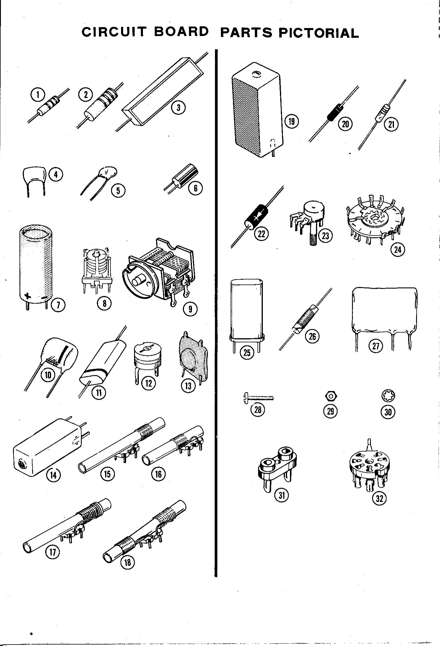
The circuit-board parts list comes first, and the instruction above it is the usual Heath discipline: unpack package #1 only, check each part against the list, and “do not open the small envelopes with part numbers on them until those parts are called for in steps.” The chassis parts come later, with their own list, after the boards are finished. Each list is followed by a parts pictorial: actual-size line drawings of every component, keyed by number to the list, so that a builder who had never seen a mica capacitor or a switch wafer could tell one from another. The introduction refers the builder to the separate “Kit Builders Guide” for unpacking, soldering and tool technique.
3.3 Switch-boards and circuit boards
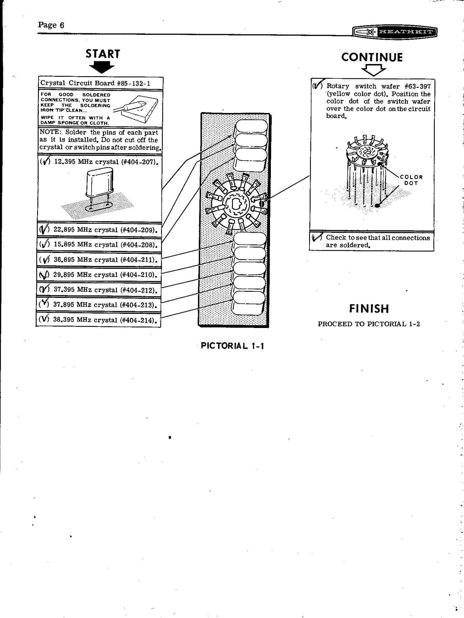
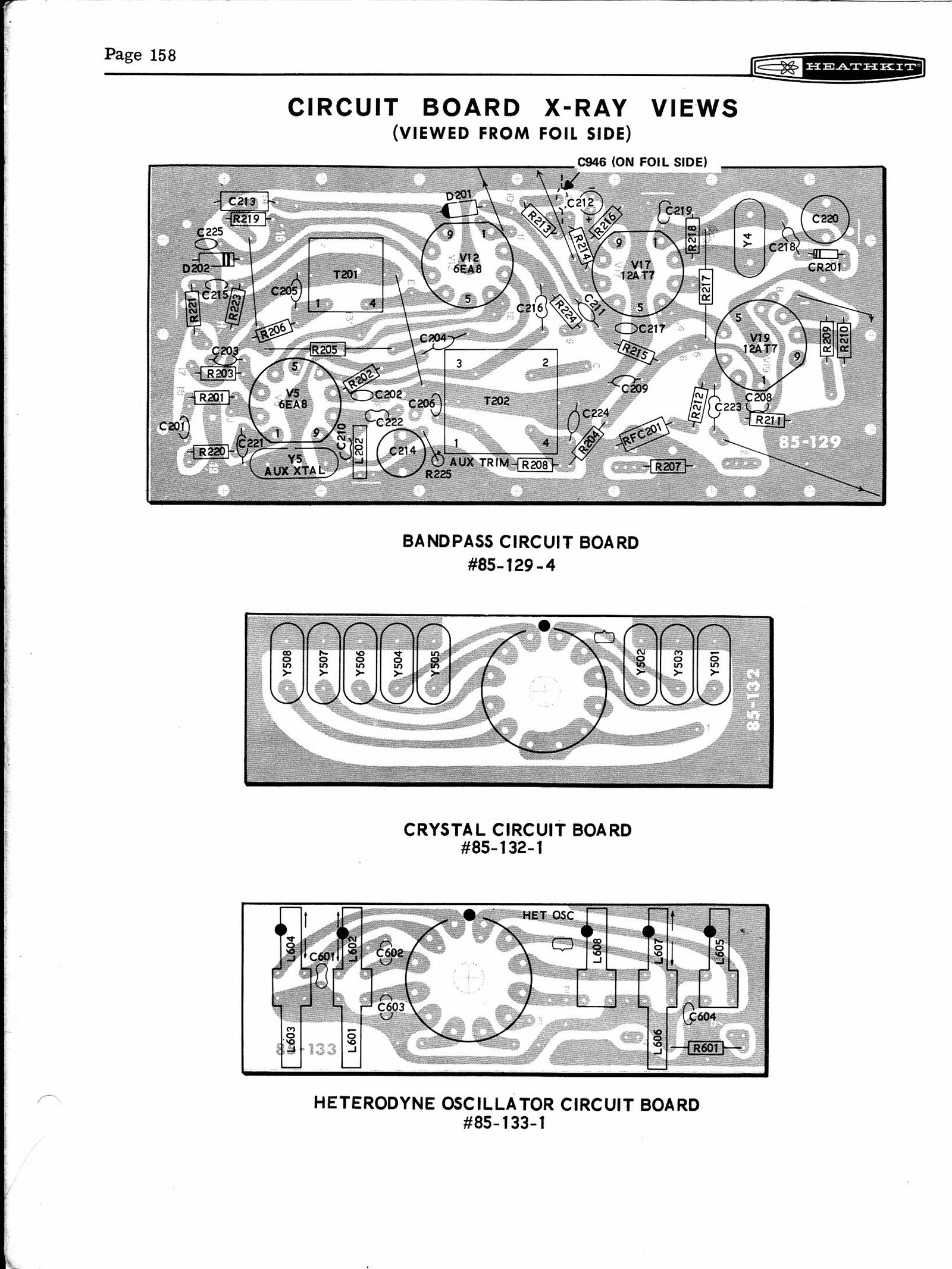
Assembly starts with the crystal circuit board, 85-132-1, a small printed board that carries the eight heterodyne crystals (12.395, 15.895, 22.895, 29.895, 36.895, 37.395, 37.895 and 38.395 MHz, Heath parts 404-207 to 404-214) with a rotary switch wafer soldered directly onto it. Three more switch-boards follow: heterodyne oscillator (85-133-1), driver grid (85-133-2) and driver plate (85-133-3). These four boards are identical in the SB-101, SB-102 and HW-101, so an SB-102 builder and an HW-101 builder did the same first evening’s work.
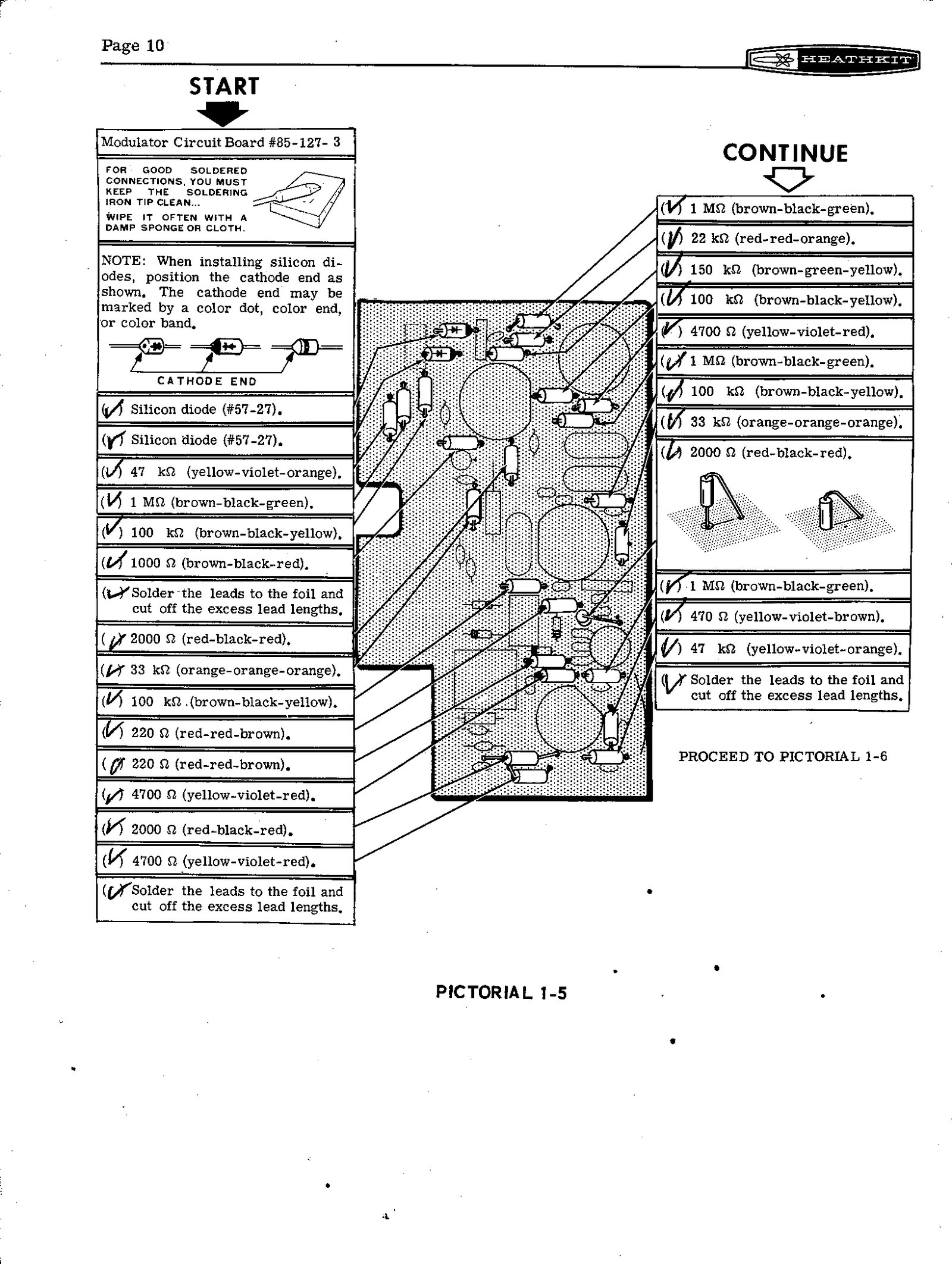
The five larger boards follow: modulator (85-127-3), IF (85-128-2), bandpass (85-129-4), audio (85-130-3) and RF driver (85-131-5). The restoration manual’s table of board part numbers shows that the modulator, bandpass, audio and RF-driver boards of the SB-102 are all different part numbers from the HW-101’s, although the circuits are close. The differences are the parts the HW line left out: the auxiliary crystal oscillator on the bandpass board, the sidetone volume control on the audio board, and the SB-102’s metering. The IF board 85-128-2 is shared with the SB-101 (restoration manual, table 11).
3.4 The chassis, and a warning about straightness
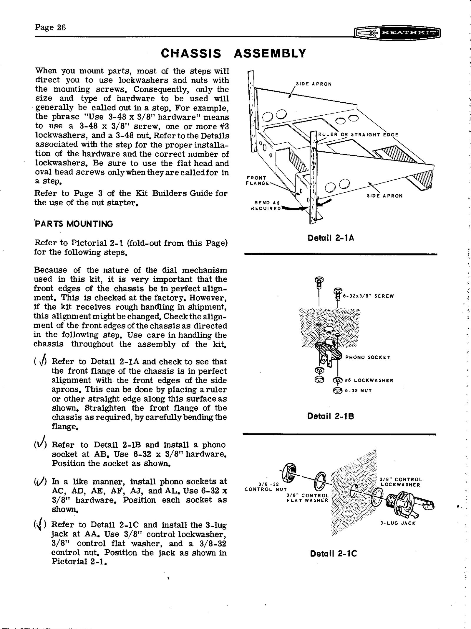
The chassis section opens with a step that has no counterpart in the HW-101 manual. The SB dial mechanism depends on the chassis front flange being exactly square, so the builder is told to lay a straight edge along it before anything else:
Because of the nature of the dial mechanism used in this kit, it is very important that the front edges of the chassis be in perfect alignment.
The factory checked this, the manual says, but rough handling in shipping could bend it; the builder was to straighten the flange “by carefully bending” it if necessary. The warning is the first sign of how much the SB dial asks of its builder.
3.5 Mounting the LMO
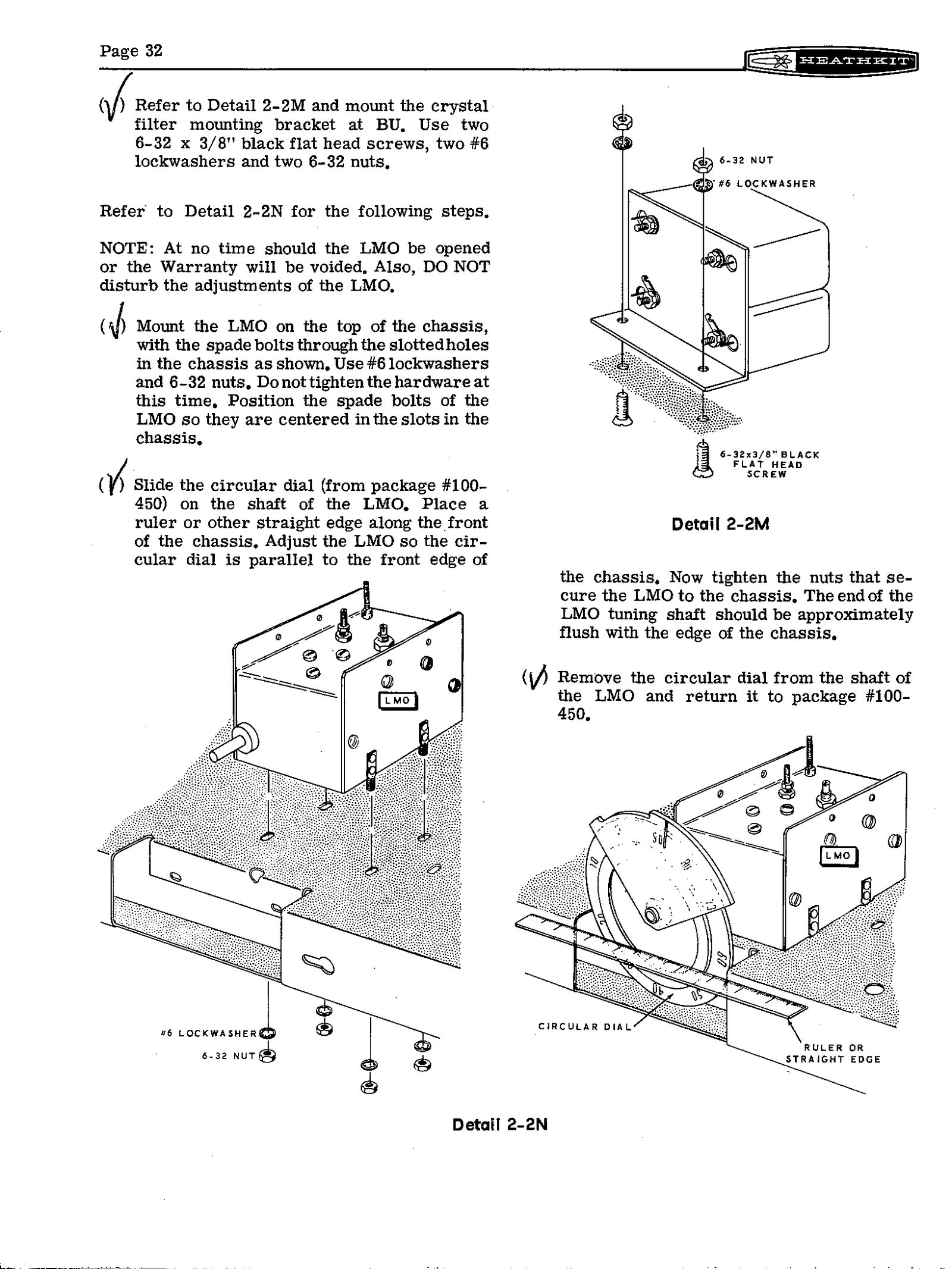
The LMO goes onto the chassis early, during parts mounting on page 32, and the instructions are fenced with warnings:
NOTE: At no time should the LMO be opened or the Warranty will be voided. Also, DO NOT disturb the adjustments of the LMO.
The LMO sits on top of the chassis on spade bolts through slotted holes, with lockwashers and nuts left loose. The builder slides the circular dial temporarily onto the LMO shaft, lays a ruler along the front of the chassis, and moves the LMO until the dial is parallel to the front edge, with the end of the tuning shaft roughly flush with the chassis. Only then are the nuts tightened, and the dial goes back in its package, #100-450, until the dial is assembled thirty pages later. The alignment matters because the dial’s pinch roller and the spiral follower both assume a dial that runs true. Heath returned to the LMO mounting after the kits were in the field: service bulletin SB-102-4 of 30 March 1973, “LMO Instability”, replaced the lockwashers and nuts on the LMO’s mounting lugs with flat washers and hex lock nuts, tightened a turn at a time in a criss-cross pattern (SB-102 service bulletins, compiled by W7LPF).
3.6 Two harnesses
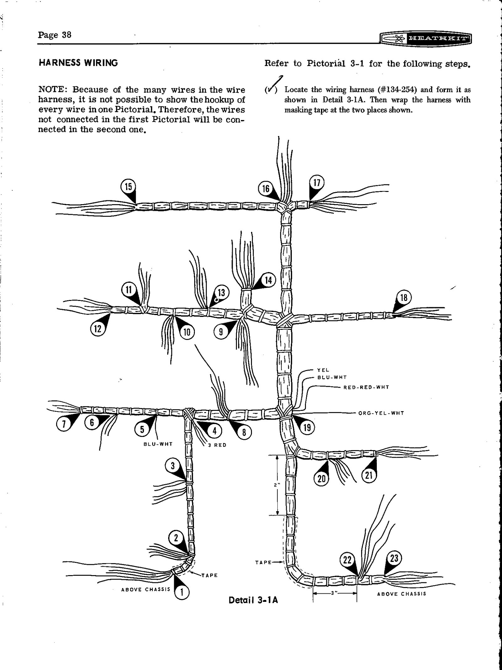
The wire harness (#134-254) arrives pre-formed and colour-coded. The builder shapes it to a drawing, tapes it at two points, lays it in the chassis and connects its breakouts one wire at a time over several pages. Unlike the HW-101, which the builder wired with four loose lengths of miniature coax, the SB-102 also has a pre-formed coaxial cable harness (#134-194), colour-coded by tape or paint and laid in beside the wire harness. The manual’s caution about coax is the same in both kits: the inner insulation “melts quite easily”, so each shield is to be soldered quickly with long-nose pliers clamped on as a heat sink, held shut with a rubber band so that both hands are free. A melted dielectric does not show on inspection and turns up later as a dead band or an unstable transmitter.
3.7 The LMO power supply chassis
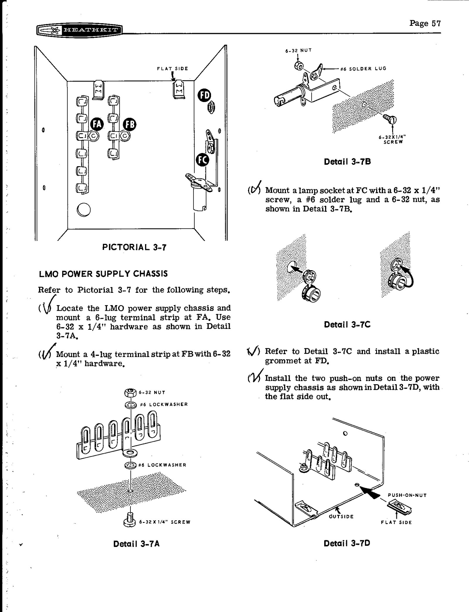
Pages 56 to 59 build the small power-supply chassis described in the circuit volume. The builder fits two terminal strips, a pilot-lamp socket used as the voltage-dropping element, a grommet and two push-on nuts. Two 500 µF electrolytic capacitors, a rectifier diode, the zener diode and the 2N3567 switching transistor are wired onto the strips, and the finished chassis is screwed onto the top of the LMO with four sheet-metal screws. The dial mounting bracket then bolts to this chassis, so the LMO, its supply and the front of the dial form one stacked assembly behind the panel. The two 500 µF capacitors are among the electrolytics the restoration manual recommends replacing on sight.
3.8 Building and calibrating the dial
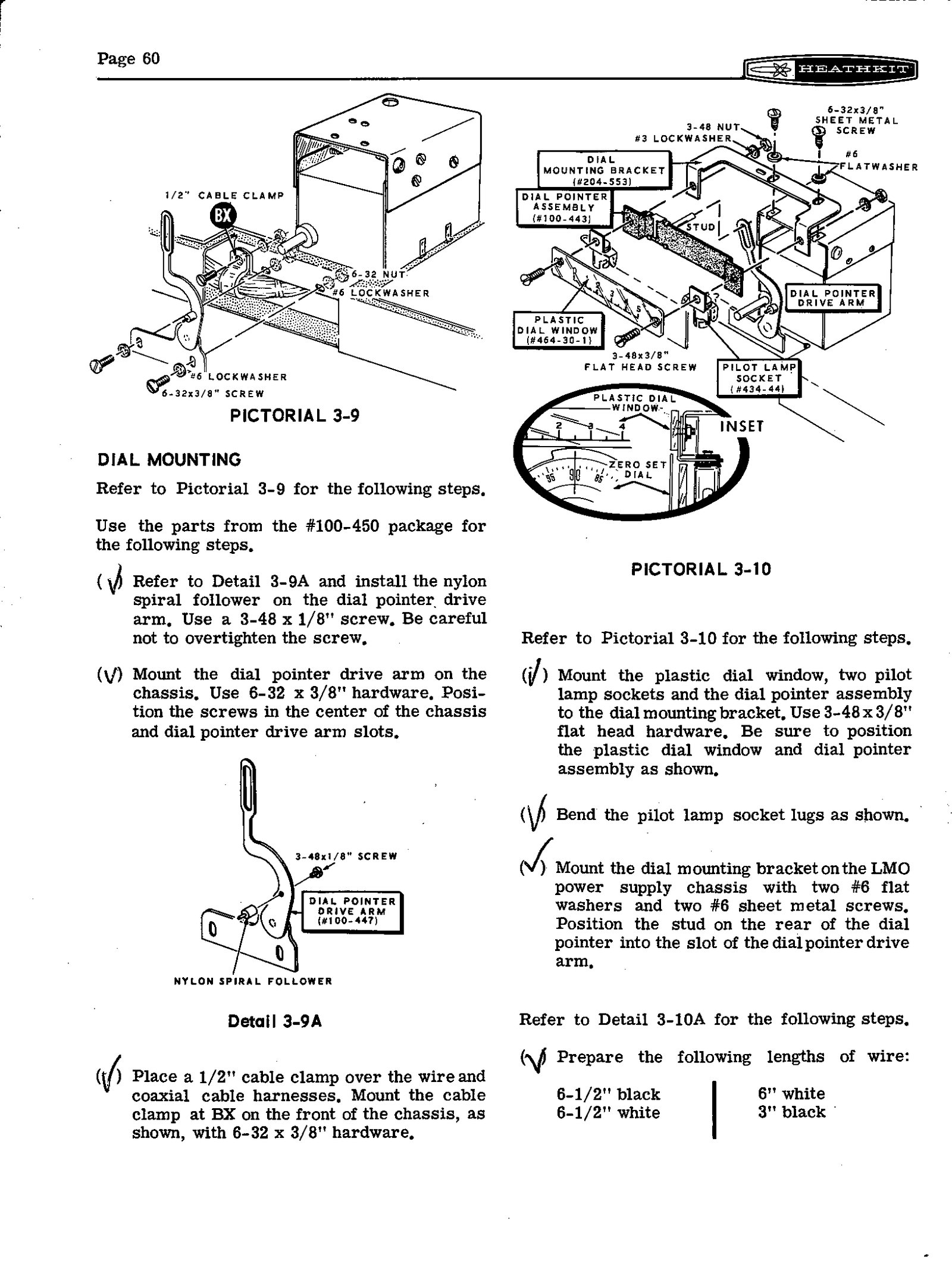
The SB dial is two readouts driven from one shaft. The circular dial, divided into one hundred 1 kHz divisions, is fixed to the LMO shaft and turns once per 100 kHz. The slide-rule window above it, marked 0 to 5, shows which 100 kHz segment the LMO is in. Its pointer is not geared to anything: a nylon follower on the pointer’s drive arm rides in a spiral groove moulded into the back of the circular dial, so the pointer steps one number for each turn. The tuning knob drives the circular dial through a pinch roller bearing on a metal ring on the dial’s inner face, a reduction of a little over four to one by Eckweiler’s account.
The builder assembles all of this from package #100-450. The nylon spiral follower goes onto the dial pointer drive arm with a screw that the manual warns against overtightening. The pointer assembly, the plastic dial window and two pilot-lamp sockets go onto the dial mounting bracket, and the bracket goes onto the LMO supply chassis. Then comes the calibration, done by hand and by eye:
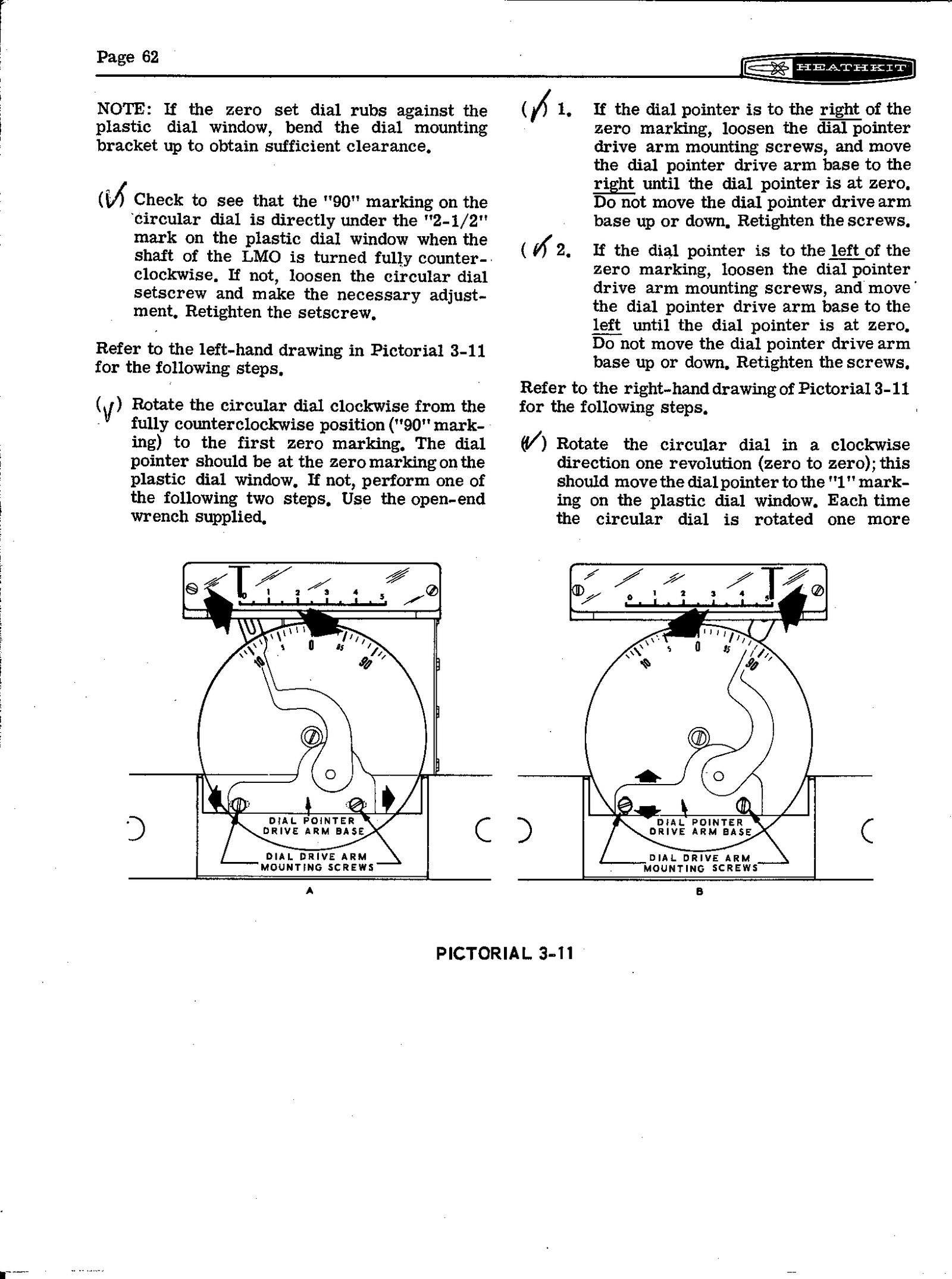
- Turn the LMO shaft fully anticlockwise against its stop, fit the circular dial with its “90” mark straight up, and engage the follower in the first groove.
- Turn the dial to its first zero. The pointer should read 0; if not, slide the drive-arm base left or right.
- Turn five full revolutions. The pointer should step one number per turn and arrive at or near 5; if not, slide the base up or down.
- Repeat until both ends agree.
The manual is candid that this is mechanical, not electrical: “Because the dial pointer is only a turns counter, it need not be exactly at a number… These adjustments in no way affect frequency calibration, which depends only on the circular dial reading.” Eckweiler’s advice to anyone buying a used SB set is to check the dial first, because a mechanism that was assembled well “feels like velvet” and one that was not can be made to with care (Heathkit of the Month #30).
3.9 Front panel and final wiring
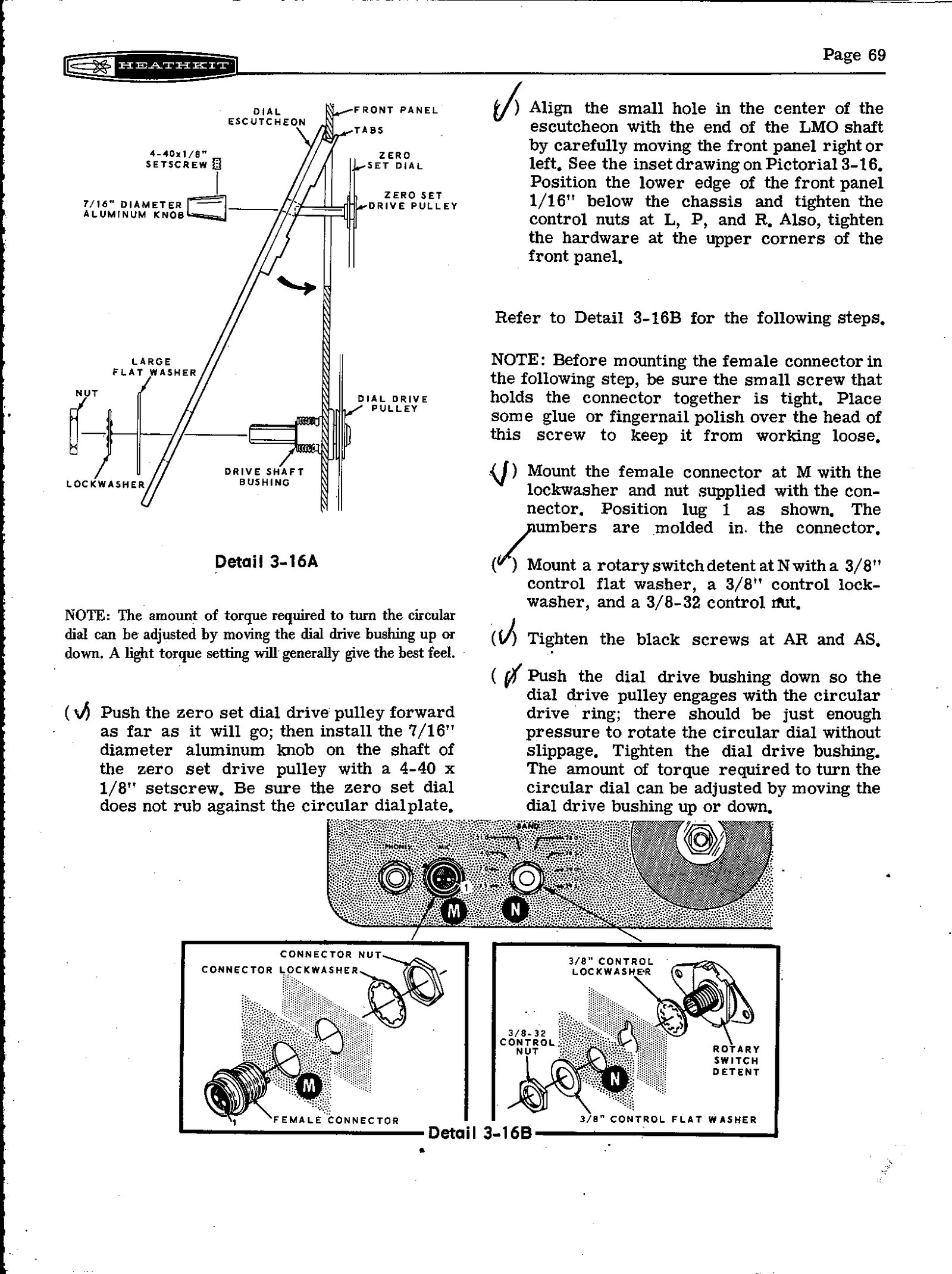
The front panel is prepared with care for its paint. The builder lays it on a soft cloth, tapes its edges, and scrapes excess paint from the inside of each hole that will take a control solder lug, so the lug makes contact. The dual-section controls, the rotary switches (MODE, BAND, FUNCTION, FREQ CONTROL and METER, where the HW-101 used slide switches for several of these), the meter and the PHONES and MIC jacks all mount before the panel goes onto the chassis. The dial escutcheon, the zero-set dial with its small pulley and knob, and the pinch-roller drive bushing go on last. A note beside the escutcheon details explains that the torque needed to turn the circular dial is adjusted by moving the dial drive bushing up or down.
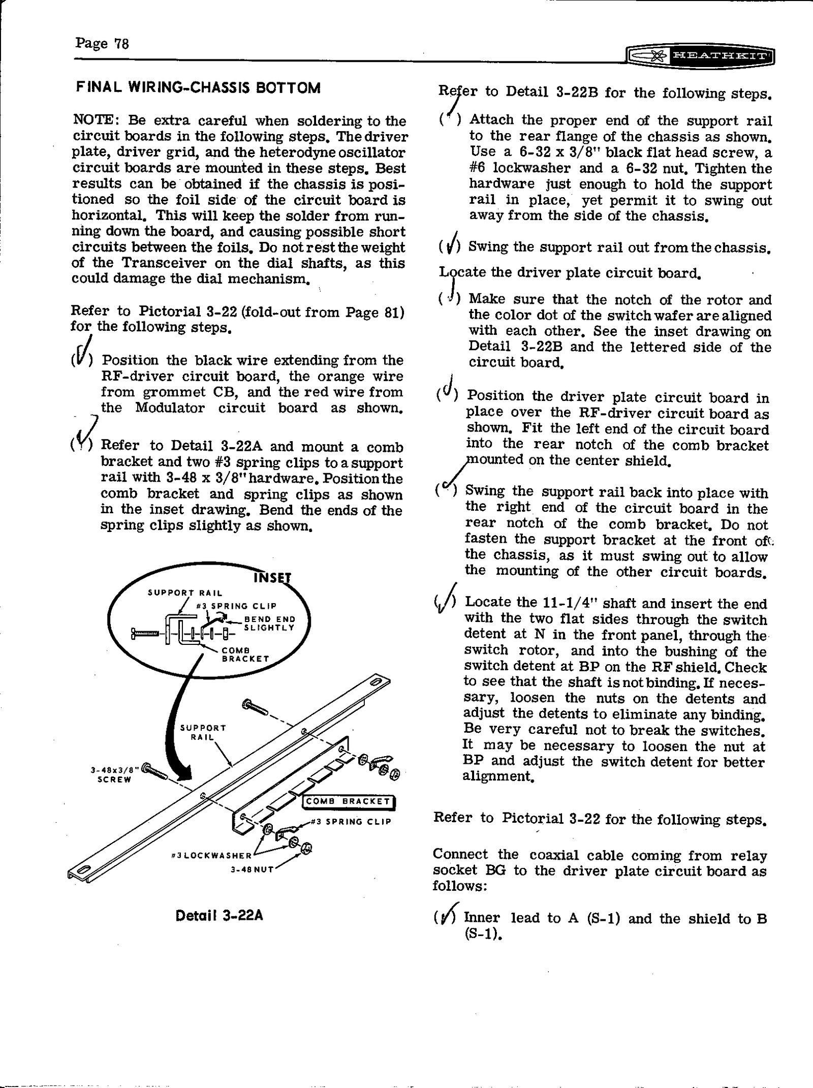
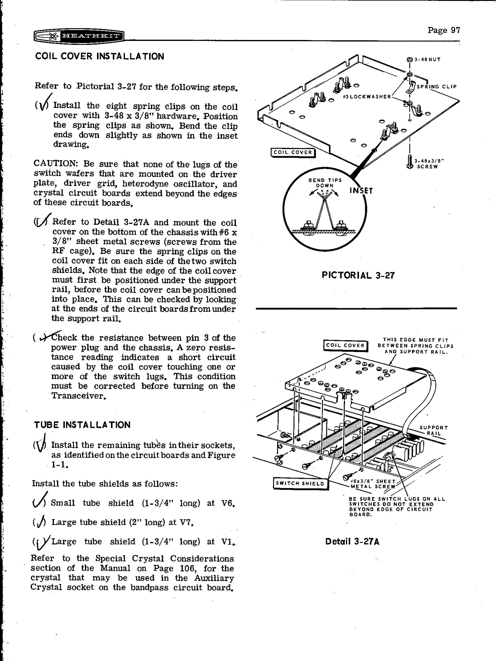
Final wiring under the chassis comes last, and the manual asks for special care there because the builder is now soldering to boards already mounted in the chassis. The driver plate board is fitted to a support rail that swings out from the chassis, so that the board can be positioned and its switch wafer lined up with the band-switch shaft before the rail swings back. Then the coil cover goes on over the switch-boards, and the manual adds a check that repays attention: measure the resistance from pin 3 of the power plug to the chassis. A zero reading means the cover is touching a switch lug that extends past the edge of a board, and that must be corrected before power is applied. The restoration manual reports the same fault in the HW-101 decades later, burning R701 or R940.
3.10 Checks before power, and the first switch-on
Pages 90 to 97 are preliminary checks. The builder first uses the transceiver’s own meter to identify the ohmmeter’s positive lead, then checks the meter circuits in the GRID, REL PWR and HV positions. Then come three charts of resistance readings, taken point by point at stated switch settings. The charts were made with a VTVM, and the manual warns that “readings made with a VOM will be considerably different” wherever a diode is in the circuit.
The power supply cable is made up next. The kit supplies the 11-pin socket, and the manual gives separate wiring for the HP-13A mobile supply and the HP-23A AC supply. With the HP-23A the supply’s own bias control is inoperative and bias is set by the control in the transceiver. The same page carries a warning for owners of older rigs: SB-100, SB-101 and HW-100 transceivers that use the same power socket must have any wire on pin 8 removed. The manual does not say why; the SB-102’s own mobile cable uses pin 8 for the jumper that feeds its LMO supply.
The initial test brings the set to life with nothing more than the panel meter. The instructions call for an earth lead to the chassis and all test equipment, the front-panel controls preset, and the transceiver’s own BIAS ADJUST fully anticlockwise. At switch-on the panel lamps should light “with equal brilliance” and the lamp in the LMO supply “glow dimly”. The meter on HV should read +800 to +900 volts, the bandpass board +300 V, and the audio board −111 V of bias. Only then does alignment begin, which is the subject of the next volume.
3.11 What it took
Heath published no build time for the SB-102 in any catalogue or manual examined here. The scale of the job shows in the manual: nine circuit boards and switch-boards, roughly eighty pages of numbered steps, a wire harness and a coax harness, a mechanical dial to calibrate by hand, and a set of resistance charts. Owners’ recollections cover the range. One eHam reviewer received his kit in March 1971 and finished it that December, and it “worked the first time I applied power”. Another thinks he built his “over about two weeks in my time off on evenings and weekends”, and his first switch-on produced smoke. A 300-volt lead that belonged in a notch in the chassis side had been pinched between the chassis and the front panel when the panel went on, and it burned out a B+ resistor. He found it, replaced the resistor, re-dressed the wire, and used the rig for years afterwards (eHam reviews).
The tools the manual asks for are modest: a small soldering iron, long-nose pliers and cutters, screwdrivers and nut drivers, the supplied nut starter and alignment tool, and an ohmmeter, ideally a VTVM. Alignment adds a dummy load and a receiver that can hear WWV.
Sources
- Heathkit Assembly Manual, SSB Transceiver Model SB-102, 595-1058-06 (Heath Company, copyright 1970), pp. 2–100 and 156–161. W5RKL scan
- Kembel, Robert W. (W5RKL), Mark (WB8JKR) and contributors. Heathkit HW-101 and SB-10x Restoration and Troubleshooting, revised 17 December 2021, table 11 (circuit board part numbers) and section b (inspection checklist). PDF
- Eckweiler, Bob (AF6C). “Heathkit of the Month #30: The Amateur Radio SB-Line Overview,” 2011, on the SB dial. PDF
- Lutz, Joseph W. (W7LPF). “Heathkit Service Bulletins: SB-102,” 1998, bulletin SB-102-4. Archive
- eHam.net, Heathkit SB-102 reviews by K1DWZ (2025) and KK5DON (2024). Link
- The Heath manual method in general: volume 8 of the site history dive; the shared HW-101 build: HW-101 dive, Building the Kit.
Comments (0)