SB-102 Transceiver · Volume 6
Reference
Everything in this volume comes from the SB-102 assembly manual, from Heath’s catalogues, or from the documents listed under Manuals and documents, and each table names its source. Where the manual and the catalogues disagree, both figures are given.
6.1 Full specification
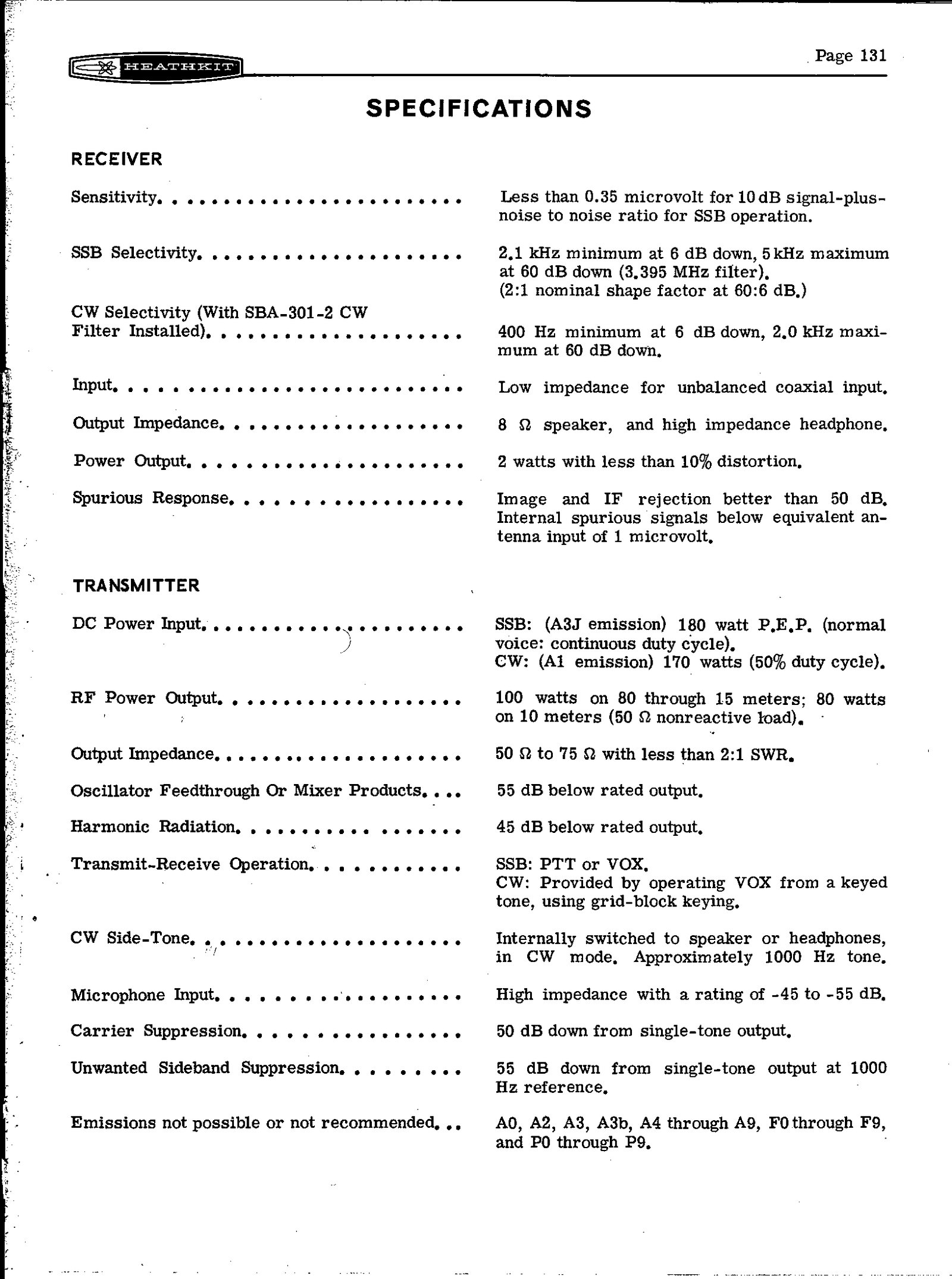
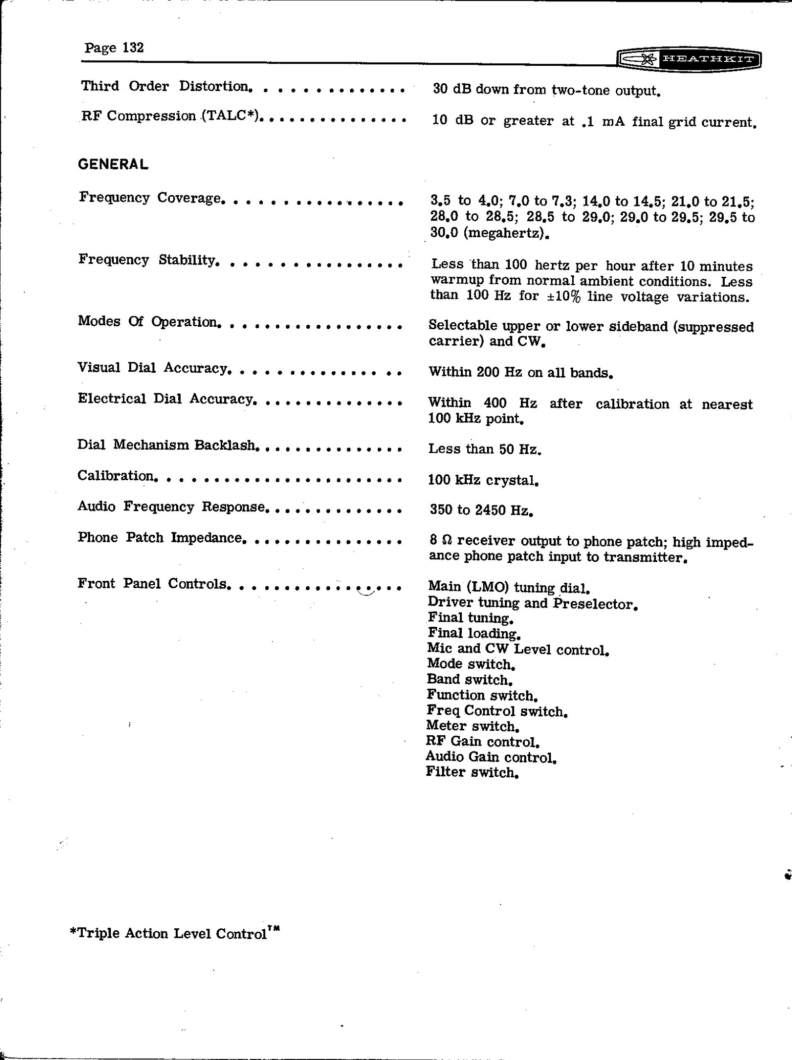
As printed in the assembly manual, edition 595-1058-06, pages 131 to 134.
6.1.1 Receiver
Table 1 — Receiver
| Sensitivity | Less than 0.35 µV for 10 dB signal-plus-noise to noise, SSB |
| SSB selectivity | 2.1 kHz minimum at 6 dB down, 5 kHz maximum at 60 dB down (3.395 MHz filter); 2:1 nominal shape factor, 60:6 dB |
| CW selectivity | With the SBA-301-2 filter installed: 400 Hz minimum at 6 dB down, 2.0 kHz maximum at 60 dB down |
| Input | Low impedance, for unbalanced coaxial input |
| Output impedance | 8 Ω speaker, and high-impedance headphones |
| Power output | 2 W with less than 10 per cent distortion |
| Spurious response | Image and IF rejection better than 50 dB; internal spurious signals below the equivalent of 1 µV at the antenna input |
6.1.2 Transmitter
Table 2 — Transmitter
| DC power input | SSB (A3J emission): 180 W PEP, normal voice, continuous duty cycle. CW (A1 emission): 170 W at 50 per cent duty cycle |
| RF power output | 100 W on 80 through 15 metres; 80 W on 10 metres, into a 50 Ω non-reactive load |
| Output impedance | 50 to 75 Ω with less than 2:1 SWR |
| Oscillator feedthrough or mixer products | 55 dB below rated output |
| Harmonic radiation | 45 dB below rated output |
| Transmit-receive operation | SSB: PTT or VOX. CW: VOX operated from a keyed tone, using grid-block keying |
| CW sidetone | About 1000 Hz, internally switched to speaker or headphones in CW |
| Microphone input | High impedance, rated −45 to −55 dB |
| Carrier suppression | 50 dB down from single-tone output |
| Unwanted sideband suppression | 55 dB down from single-tone output at 1000 Hz reference |
| Third-order distortion | 30 dB down from two-tone output |
| RF compression (TALC) | 10 dB or greater at 0.1 mA final grid current |
| Emissions not possible or not recommended | A0, A2, A3, A3b, A4 through A9, F0 through F9, P0 through P9 |
6.1.3 General
Table 3 — General
| Frequency coverage | 3.5–4.0; 7.0–7.3; 14.0–14.5; 21.0–21.5; 28.0–28.5; 28.5–29.0; 29.0–29.5; 29.5–30.0 MHz |
| Frequency stability | Less than 100 Hz per hour after 10 minutes’ warm-up from normal ambient conditions; less than 100 Hz for ±10 per cent line voltage variation |
| Modes | Selectable upper or lower sideband (suppressed carrier) and CW |
| Visual dial accuracy | Within 200 Hz on all bands |
| Electrical dial accuracy | Within 400 Hz after calibration at the nearest 100 kHz point |
| Dial backlash | Less than 50 Hz |
| Calibration | 100 kHz crystal |
| Audio frequency response | 350 to 2450 Hz |
| Phone patch impedance | 8 Ω receiver output to the patch; high-impedance patch input to the transmitter |
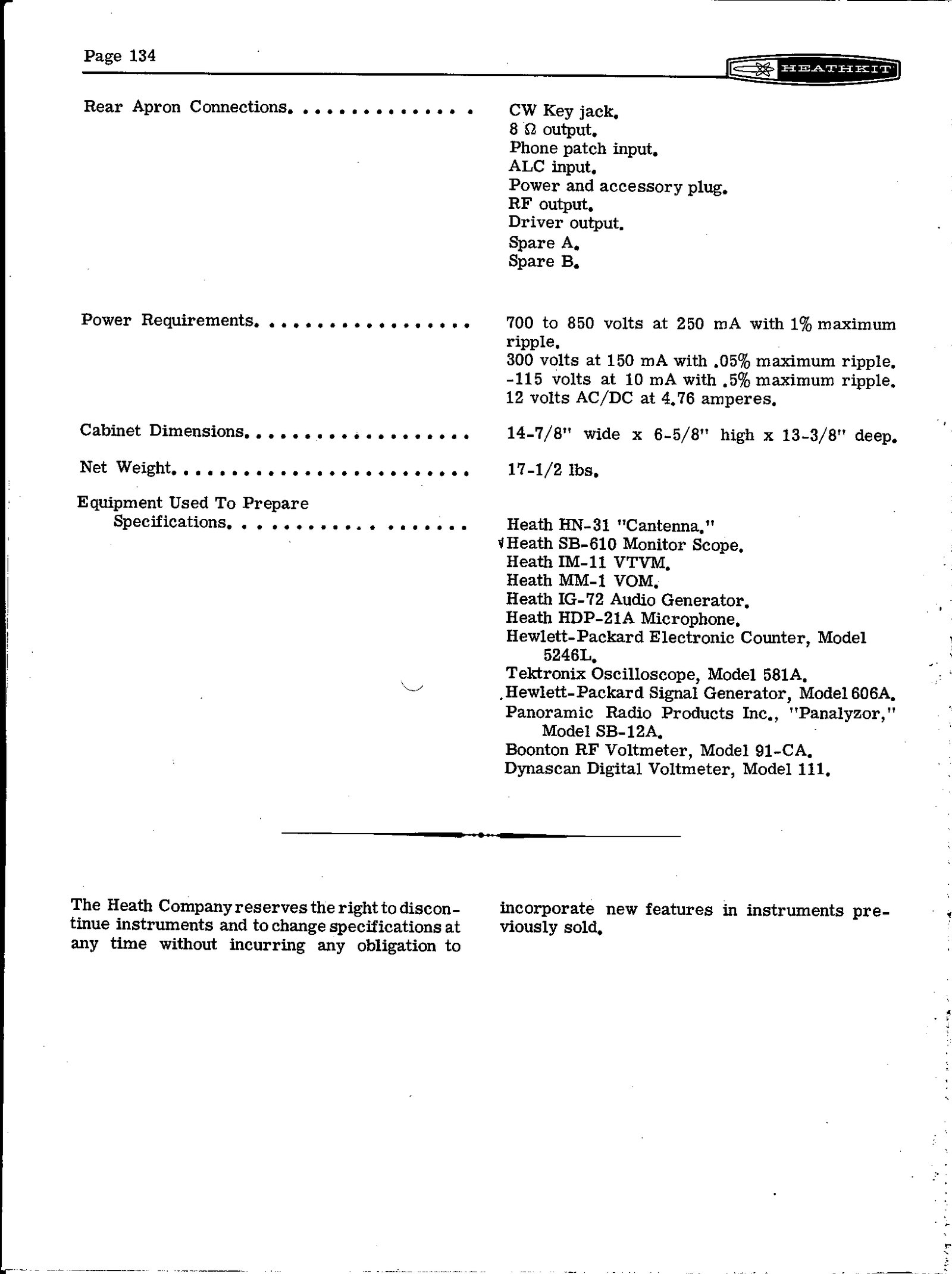
| Cabinet | 14⅞ in wide × 6⅝ in high × 13⅜ in deep |
| Net weight | 17½ lb |
| Power required | 700–850 V at 250 mA (1 per cent maximum ripple); 300 V at 150 mA (0.05 per cent); −115 V at 10 mA (0.5 per cent); 12 V AC or DC at 4.76 A |
The catalogue specification blocks differ from the manual in small ways, and the differences are worth knowing when comparing sources.
- Audio output. The 1971 catalogue block gives the receiver output as “unbalanced 8 and 600 ohm speaker”. The 600 Ω output belonged to the SB-100, and the SB-102 manual lists only 8 Ω.
- A misprinted backlash figure. The same 1971 block gives dial backlash as “less than 50 kHz”, an evident misprint for the manual’s 50 Hz.
- A figure the manual lacks. The catalogues add “noise level: at least 40 dB below single-tone carrier”, which the manual’s specification pages do not include.
- High voltage. The 1973 catalogue gives the high-voltage requirement as 700 to 800 volts, against the manual’s 700 to 850.
The manual also lists the equipment Heath used to prepare these specifications: the HN-31 Cantenna, the SB-610 monitor scope, an IM-11 VTVM, an MM-1 VOM, an IG-72 audio generator and an HDP-21A microphone from its own range, together with a Hewlett-Packard counter and signal generator, a Tektronix 581A oscilloscope, a Panoramic Panalyzor SB-12A, a Boonton 91-CA RF voltmeter and a Dynascan digital voltmeter.
6.2 Tube and semiconductor complement
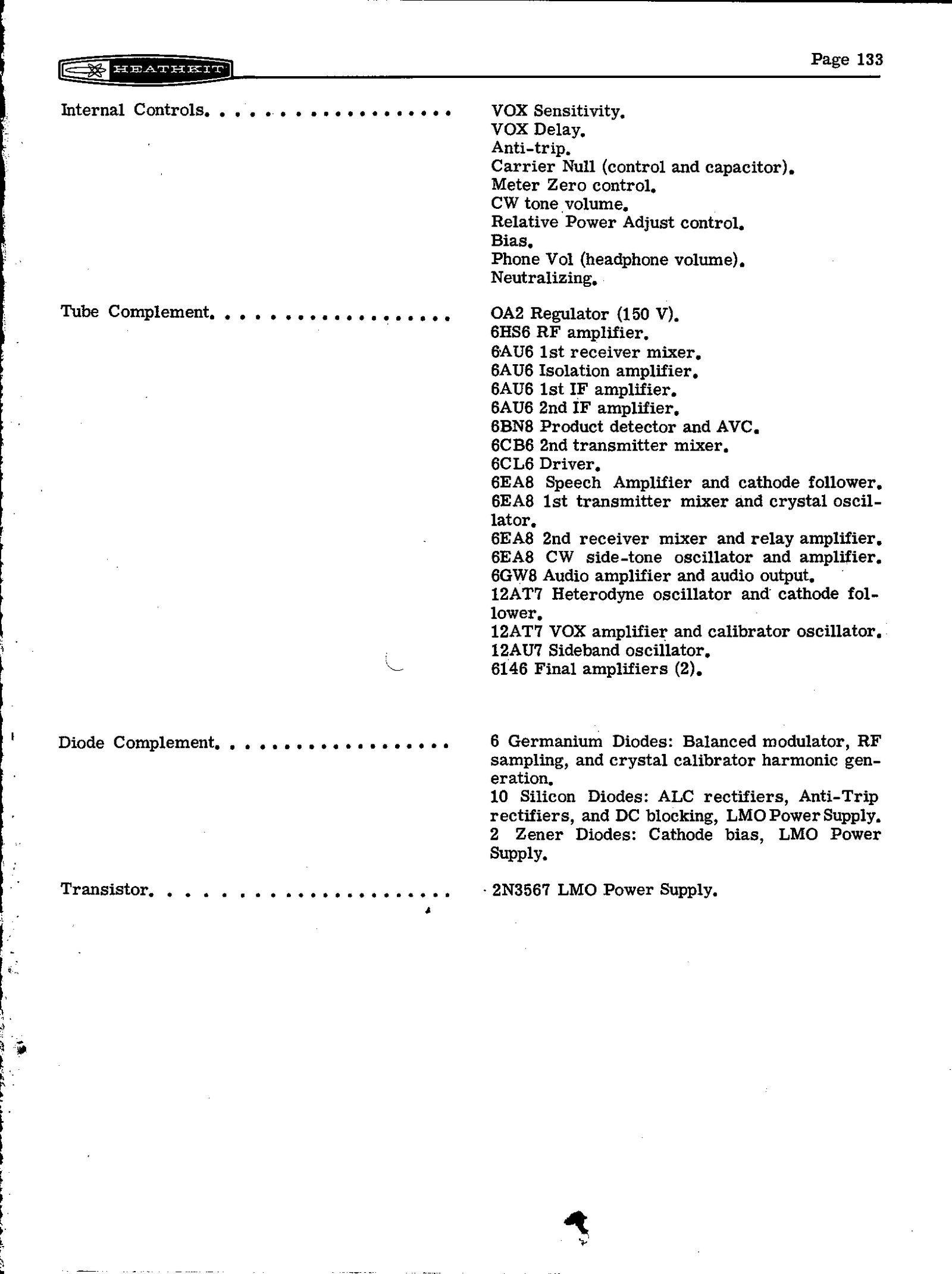
Twenty tubes, from the manual’s specification page 133. The designators are from the Circuit Description.
Table 4 — Tube and semiconductor complement
| Type | Function | Designator |
|---|---|---|
| OA2 | Voltage regulator, 150 V | V18 |
| 6HS6 | RF amplifier | V10 |
| 6AU6 | First receiver mixer | V11 |
| 6AU6 | Isolation amplifier | V2 |
| 6AU6 | First IF amplifier | V3 |
| 6AU6 | Second IF amplifier | V4 |
| 6BN8 | Product detector and AVC | V13 |
| 6CB6 | Second transmitter mixer | V6 |
| 6CL6 | Driver | V7 |
| 6EA8 | Speech amplifier and cathode follower | V1 |
| 6EA8 | First transmitter mixer and auxiliary crystal oscillator | V5 |
| 6EA8 | Second receiver mixer and relay amplifier | V12 |
| 6EA8 | CW sidetone oscillator and amplifier | V15 |
| 6GW8 | Audio amplifier and audio output | V14 |
| 12AT7 | Heterodyne oscillator and cathode follower | V19 |
| 12AT7 | VOX amplifier and calibrator oscillator | V17 |
| 12AU7 | Sideband (carrier) oscillator | V16 |
| 6146 | Final amplifier | V8 |
| 6146 | Final amplifier | V9 |
Against the SB-101, the list differs in three places: the 6HS6 RF amplifier where the SB-101 had a 6AU6; no 6CB6 LMO, because the SB-101’s tube LMO is gone; and the transistor LMO in its place.
Semiconductors (manual p. 133): 6 germanium diodes (balanced modulator, RF sampling, calibrator harmonic generation); 10 silicon diodes (ALC rectifiers, anti-trip rectifiers, DC blocking, LMO power supply); 2 zener diodes (relay-amplifier cathode bias, LMO power supply); one transistor, a 2N3567, in the LMO power supply. The sealed LMO’s own transistors are not listed. The manual’s introduction counts “twenty tubes, four transistors, and eighteen diodes”; the redrawn LMO schematic shows four transistors inside the LMO, so with the 2N3567 the total would be five. This dive has not resolved the difference.
6.3 Frequency data
From figure 2-2 of the manual. All frequencies in MHz.
Table 5 — Frequency data
| Band | LMO (example) | First IF at bandpass filter | Heterodyne crystal | Transmitted (example) |
|---|---|---|---|---|
| 3.5–4.0 | 5.105 | 8.5 | 12.395 | 3.895 |
| 7.0–7.3 | 5.3 | 8.695 | 15.895 | 7.2 |
| 14.0–14.5 | 5.3 | 8.695 | 22.895 | 14.2 |
| 21.0–21.5 | 5.2 | 8.595 | 29.895 | 21.3 |
| 28.0–28.5 | 5.4 | 8.795 | 36.895 | 28.1 |
| 28.5–29.0 | 5.3 | 8.695 | 37.395 | 28.7 |
| 29.0–29.5 | 5.3 | 8.695 | 37.895 | 29.2 |
| 29.5–30.0 | 5.4 | 8.795 | 38.395 | 29.6 |
Carrier crystals: Y1 3396.4 kHz (USB and CW receive), Y2 3393.6 kHz (LSB), Y3 3395.4 kHz (CW transmit). Crystal filter FL1: centre 3395 kHz, 3393.95–3396.05 kHz at the 6 dB points. LMO: 5.5 MHz at the low edge of each band to 5.0 MHz at the top, 100 kHz per turn. Calibrator: 100 kHz.
6.4 Selected part numbers and prices
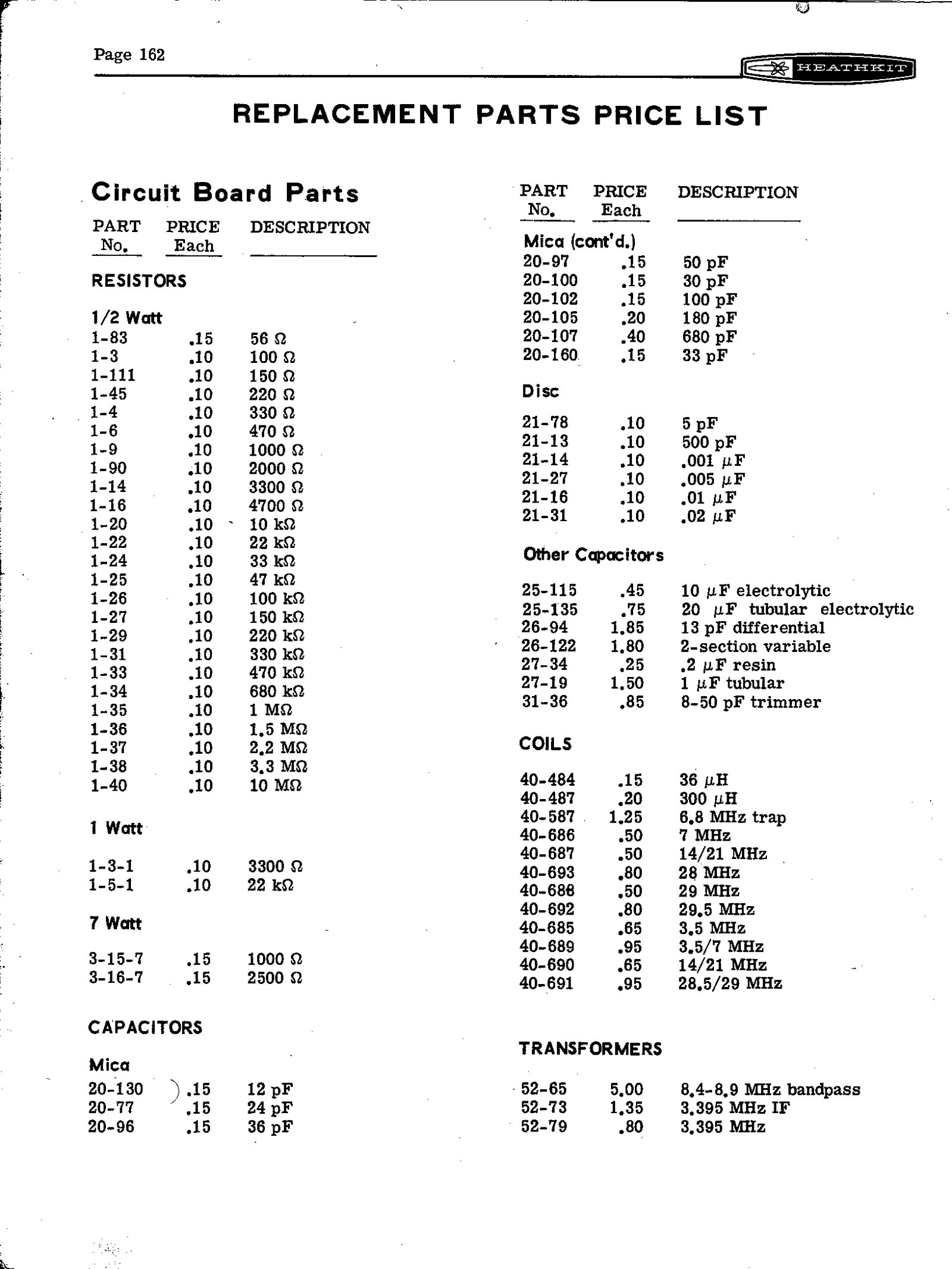
From the manual’s replacement parts price list (pages 162–166), in the W5RKL copy of edition 595-1058-06.
Table 6 — Selected part numbers and prices
| Part | Heath number | Price |
|---|---|---|
| LMO (linear master oscillator) | 110-48 | $94.00 |
| 2.1 kHz crystal filter | 404-283 | $35.50 |
| Carrier crystal, 3393.6 kHz | 404-205 | $5.00 |
| Carrier crystal, 3395.4 kHz | 404-215 | $4.50 |
| Carrier crystal, 3396.4 kHz | 404-206 | $5.00 |
| Heterodyne crystals, 12.395 to 38.395 MHz | 404-207 to 404-214 | $4.35 each |
| 6146 | 411-75 | $4.35 |
| 6HS6 | 411-247 | $1.70 |
| 6EA8 | 411-124 | $1.50 |
| Wiring harness | 134-254 | — |
| Coaxial cable harness | 134-194 | — |
| Circuit boards | 85-127-3 (modulator), 85-128-2 (IF), 85-129-4 (bandpass), 85-130-3 (audio), 85-131-5 (RF driver), 85-132-1 (crystal), 85-133-1/-2/-3 (heterodyne oscillator, driver grid, driver plate) | — |
6.5 Controls and connections
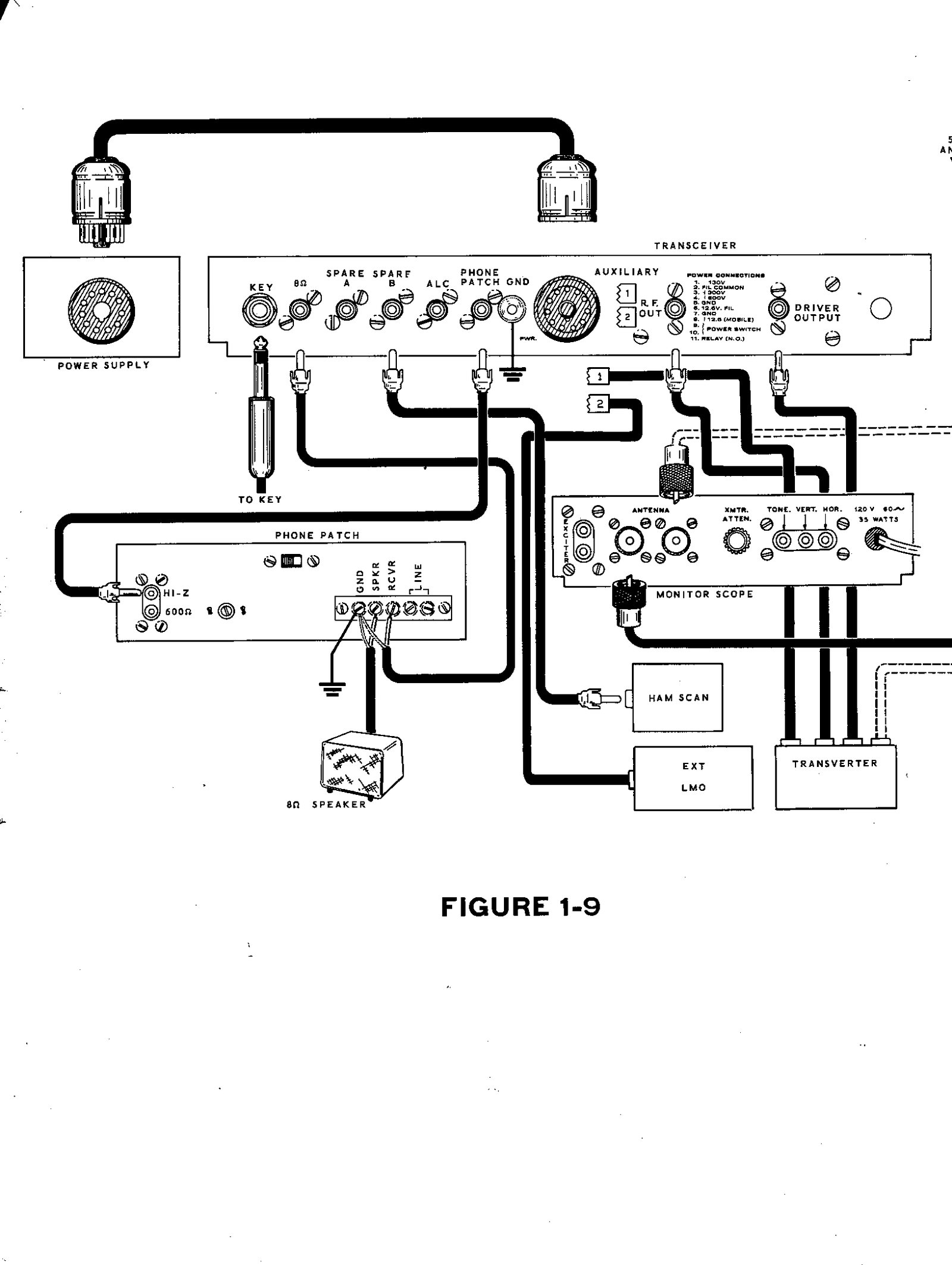
Front panel: main tuning (LMO) dial with zero-set dial; DRIVER PRESELECTOR; FINAL tuning; FINAL loading; MIC/CW LEVEL; MODE; BAND; FUNCTION; FREQ CONTROL; METER; RF GAIN with the FILTER switch; AF GAIN; PHONES jack; MIC connector.
Internal (under the hinged lid): VOX SENSITIVITY; VOX DELAY; ANTI-TRIP; CARRIER NULL control and capacitor; METER ZERO; CW-TONE VOLUME; RELATIVE POWER adjust; BIAS; PHONE VOL; NEUTRALIZING; CAL XTAL and AUX TRIM trimmers; LSB ADJUST on the LMO.
Rear apron: CW key jack; 8 Ω output; phone patch input; ALC input; power and accessory plug (11-pin); RF output; driver output; spare A; spare B.
6.6 Heath accessories
Prices are kit prices from the catalogue named, all from World Radio History scans.
Table 7 — Heath accessories
| Model | What it is | Price and catalogue |
|---|---|---|
| HP-23, HP-23A, HP-23B | AC power supply for the SB and HW transceivers; the -A added 120/240 V primaries | $51.95 (HP-23A, 1971; HP-23B, 810/74) |
| HP-13, HP-13A, HP-13B | Solid-state 12 V mobile supply | $69.95 (HP-13A, 1971; HP-13B, 810/74) |
| SB-600 | Matching speaker, 6 × 9 in oval, with space inside for an HP-23 | $19.95 (1971; 810/74) |
| SBA-301-2 | 400 Hz CW crystal filter, front-panel switched | $21.95 (1971); $22.95 (810/74) |
| SBA-100-1 | Mobile mounting bracket | $14.95 (1971); $15.95 (810/74) |
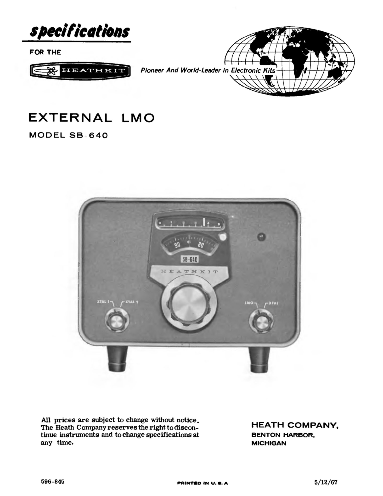
| SB-640 | External LMO for split and crystal operation, designed for the SB-101 | $99.00 (1968, 1969) |
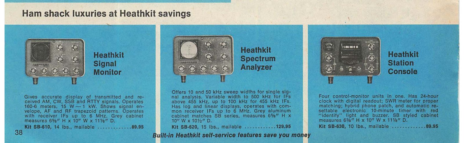
| SB-610 | Monitor scope: transmitted and received envelopes, trapezoid patterns | $79.95 (1971); $89.95 (810/73) |
| SB-620 | Spectrum monitor (“panadapter”) | $119.95 (1971); $129.95 (810/73) |
| SB-630 | Station console: 24-hour clock, 10-minute timer, SWR bridge, hybrid phone patch | $79.95 (1971); $89.95 (810/73) |
| SB-650 | Digital frequency display, six Nixie tubes, for SB and HW transceivers | $179.95 (810/73) |
| SB-500 | Two-metre transverter, driven from the SB-102’s DRIVER OUTPUT jack | $179.95 (Winter 1970) |
| SB-200 | 1200 W PEP linear, two 572B | $220.00 (1971) |
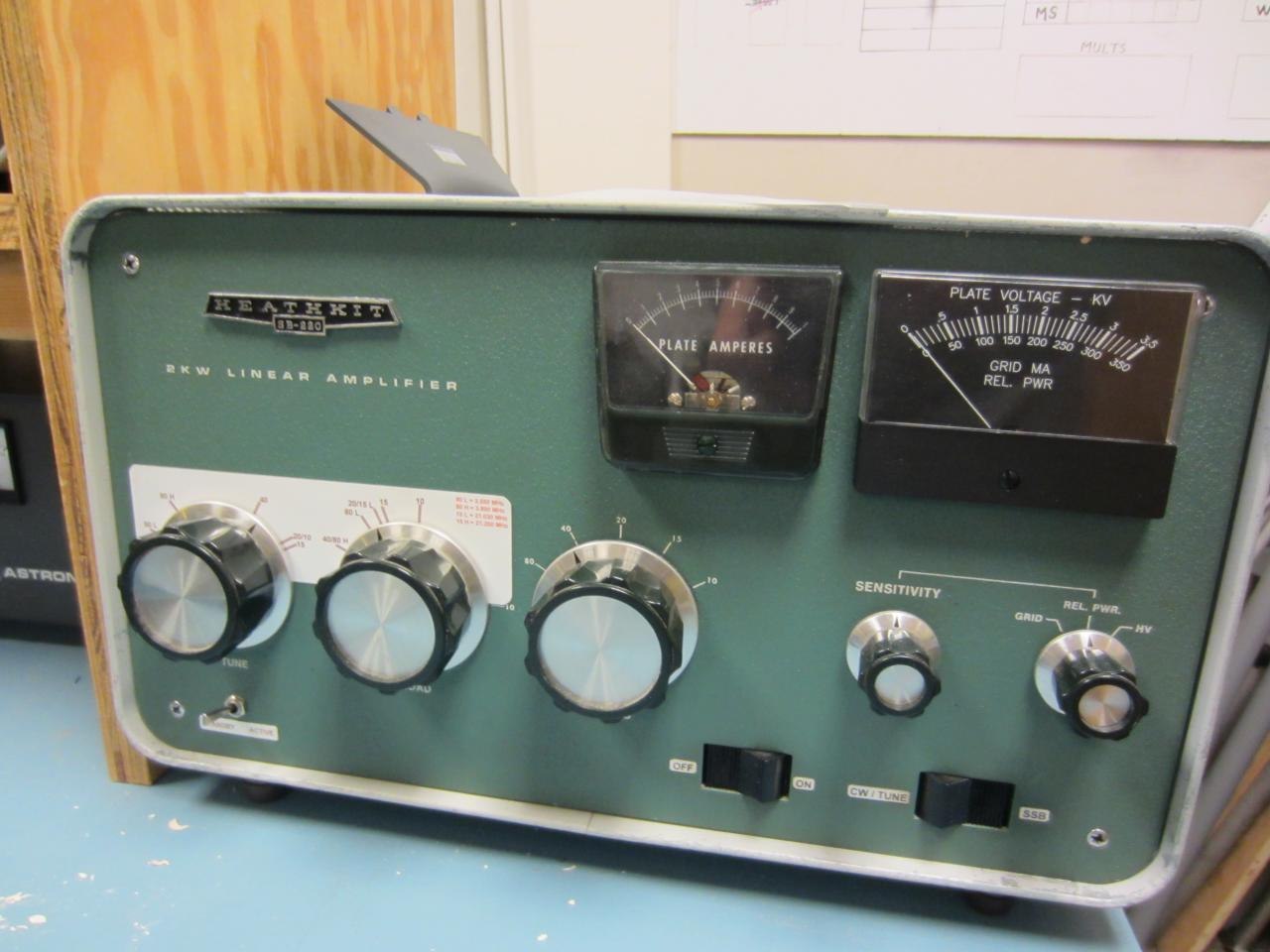
| SB-220 | 2 kW PEP linear, two 3-500Z | $349.95 (1971); $369.95 (810/72) |
| HDP-21A | Desk microphone matched to the SB series | $29.40 (1969) |
The HP-23 family’s revisions (HP-23 of 1963, 23A of 1968, 23B of 1973, 23C of 1978, and PS-23) are summarised, with Eckweiler’s account, in the HW-101 dive’s reference volume. All of them run an SB-102. When one is wired to the SB-102 as the manual describes, the supply’s own bias control is inoperative and bias is set by the control in the transceiver.

6.7 Manuals and documents
The project’s rule is to host a Heath publication only when it is likely to be in the public domain, and otherwise to link the best free copy. The likely-public-domain cases are publication before 1964 with no renewal found, or publication without a copyright notice before 1 March 1989, with the additional condition of no registration within five years for 1978–89. For each title below the dive records the year, whether a notice was seen, and whether a renewal search was done. No renewal search has been done for any of them.
Assembly manual, SSB Transceiver Model SB-102 — Heath part 595-1058-06.
- Publication year: copyright 1970 (cover: “Copyright © 1970, Heath Company, All rights reserved”).
- Copyright notice seen: yes, on the cover.
- Renewal search: not done.
- Hosting decision: link only, do not host. The manual is dated 1970 and carries a notice.
- The only edition identified is -06. The W5RKL scan is a later printing: its warranty page refers to retail “Heathkit Electronic Centers”, and its contents include a “Factory Repair Service” section. The scan used by the Internet Archive and the NF4RC copy covers only pages 88 onward and has no cover or part number visible, so its edition is not known.
| Where | Notes |
|---|---|
| W5RKL, SB-102 Full Assembly Manual | Complete, 214 pages including fold-outs, from W5RKL’s manuals page; the scan used for every manual figure in this dive |
| archive.org/details/Heathkit_SB-102_SSB_Transciever | heathkitmanuals collection. 78 pages: the Heath (Gloucester) specification sheet, contents, and manual pages 88 to about 165. Text layer available |
| NF4RC, SB102Manual.pdf | The same partial scan, from the BoatAnchor Manual Archive, with its cover sheet |
| W5RKL, SB-102 Schematic · SB-102 Alignment and Schematic | Extracts |
| vintage-radio.info | Heathkit manual and schematic archive, rate-limited |
No copy of the SB-102 manual was found in the Internet Archive’s DLARC collection at the time of writing.
Heath (Gloucester) Ltd specification sheet, SB-102. Two pages, undated but after the SB-102’s 1970 launch, with the Schlumberger badge. No copyright notice was seen on the sheet as scanned, and no renewal search was done. As advertising published before 1978 apparently without notice, it is a candidate for hosting under the project rule, subject to checking an original for a notice. It survives bound ahead of the manual in the Internet Archive and NF4RC scans.
Service bulletins. Heath issued bulletins SB-102-1 (25 November 1970) to at least SB-102-30 (21 September 1984). The titles, dates and a one-line summary of each are in Joseph Lutz’s (W7LPF) compiled list on the Heath mailing list archive; bulletins 11 to 13 are missing from it, and 26 to 29 are listed by title only. The bulletins themselves were not located as scans.
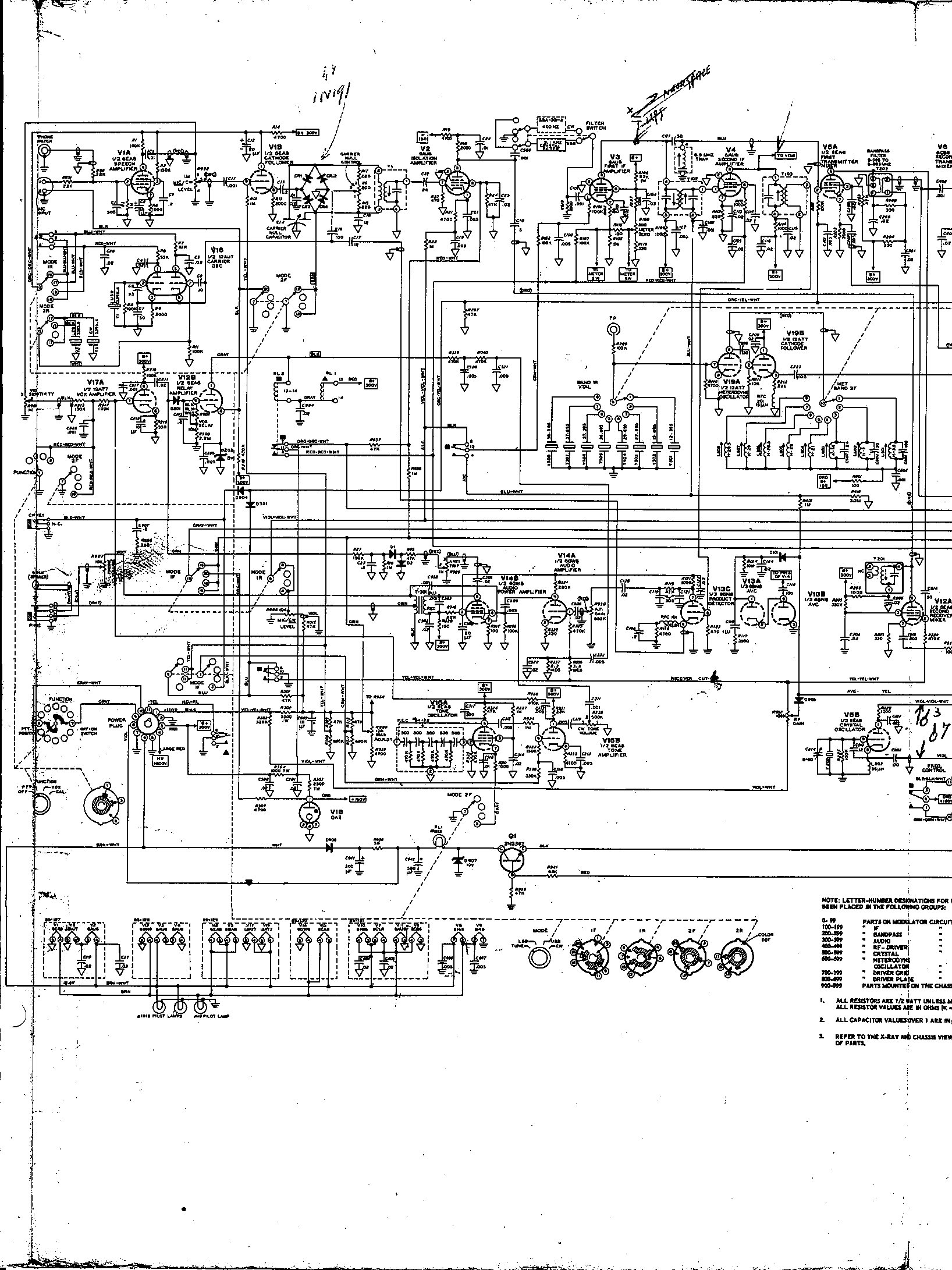
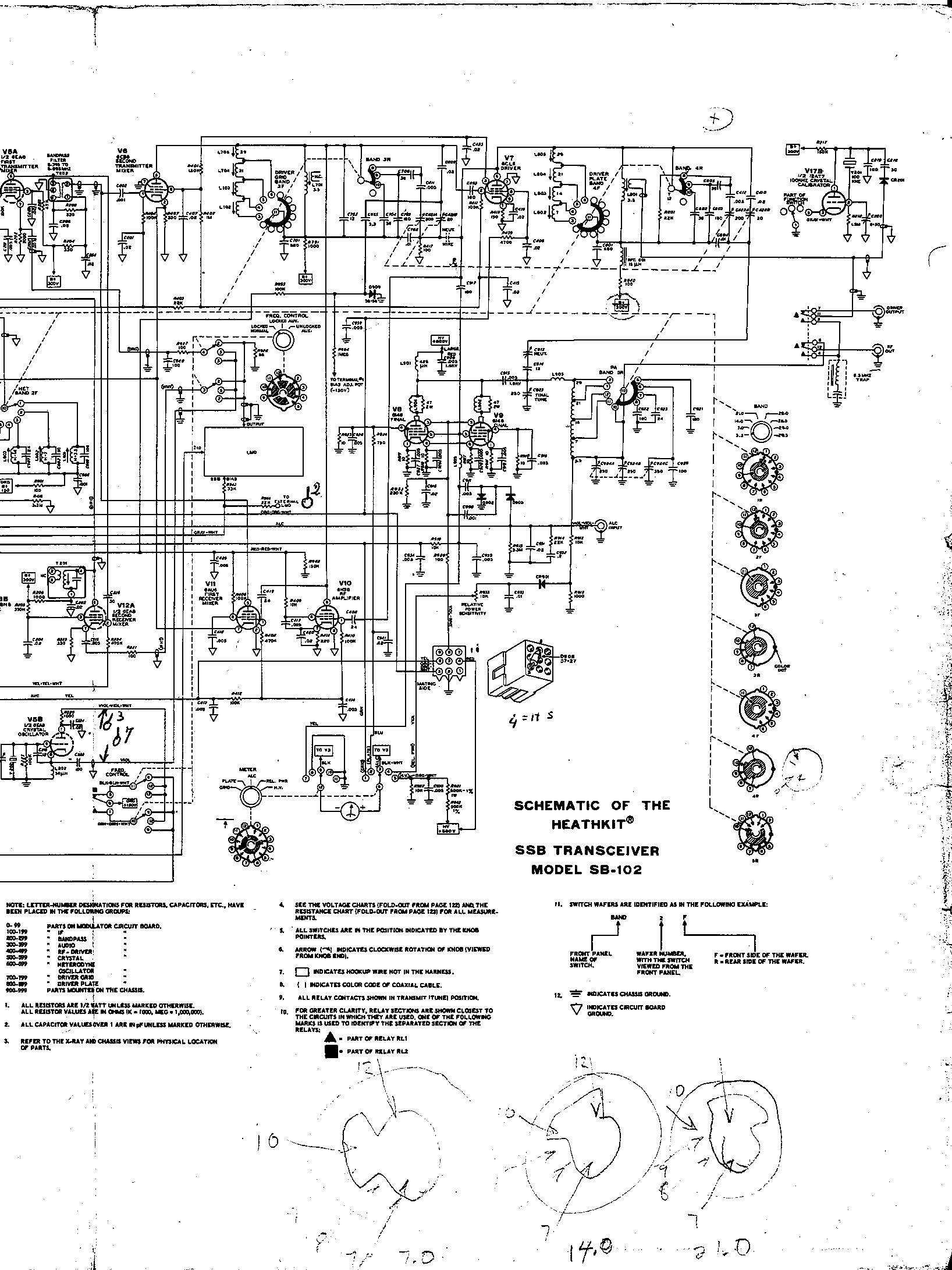
The LMO schematic. No Heath schematic of the solid-state LMO was published, by design. The redrawn schematic by J. Flanagan (WB5KYE), 2004, from a TRW-attributed original of 24 September 1969, is on the Internet Archive. It is a third-party drawing, so it is linked, not hosted.
Predecessor and relative manuals.
Table 8 — Predecessor and relative manuals.
| Title | Part number and date | Notice | Where |
|---|---|---|---|
| SB-100 manual (partial, 8 pp.) and SB-100 alignment | not seen | not seen in the partial scan | IA SB-100 · IA SB-100 alignment |
| SB-101 manual | 595-840 (listed as “Manual, $2.00” in the SB-101 parts list); year not seen | not seen in the partial scan | W5RKL, complete · IA, partial |
| SB-110A manual | not seen; cover price $2.00 | not seen in the scan’s text layer | IA |
| SB-600 speaker manual | 595-815 (as listed in its parts list); copyright 1966 | yes | IA |
| SB-630 station console | not seen | not seen (3-page extract) | IA |
| SB-640 specification sheet and schematic | form 596-845, printed 12 May 1967 | not seen (3-page extract) | IA |
| SB-610 monitor scope manual | — | do-not-host list (Tubular Electronics); link only | IA, heathkitmanuals · IA, DLARC |
| SB-200 linear amplifier manual | 1964 per IA metadata | not checked | IA, DLARC |
| SB-220 service and user information | — | not checked | W5RKL |
| HP-23A power supply manual | — | not checked | W5RKL |
For the SB-100, SB-110A, SB-630 and SB-640, “not seen” means only that the partial scans do not show a notice. The originals probably carried one, and none of them should be treated as a hosting candidate without checking a complete copy.
Catalogues. Every catalogue cited in this dive is on World Radio History’s Heathkit catalogue index. Under the project rule, catalogues count as advertising and are handled in the same way as the manuals until a renewal check has been done.
6.8 Related Heath equipment
Table 9 — Related Heath equipment
| Model | Relationship |
|---|---|
| SB-300, SB-400 (1963–64) | The receiver and transmitter that established the SB system and its LMO |
| SB-100 (1965–66), SB-101 (1967) | The SB-102’s direct predecessors, with tube LMOs (110-32 and 110-40) |
| SB-110, SB-110A (1965, 1969) | The six-metre transceivers in the same styling |
| SB-301, SB-401 | The separate receiver and transmitter of the same generation; see the SB-301/SB-401 dive |
| SB-303, SB-313 | Solid-state receivers; the restoration manual states that they use the same LMO as the SB-102 |
| HW-100 (1968), HW-101 (1970) | The cost-reduced HW transceivers; the HW-101 was derived from the SB-102 (HW-101 dive) |
| SB-104, SB-104A (1974, 1977) | The solid-state transceiver that replaced the SB-102; see the SB-104A dive |
Further reading
- Heathkit Assembly Manual, SSB Transceiver Model SB-102, 595-1058-06 (Heath Company, 1970). The primary source for everything technical in this dive. W5RKL
- Kembel, Robert W. (W5RKL), Mark (WB8JKR) and contributors. Heathkit HW-101 and SB-10x Restoration and Troubleshooting (2021). The most complete practical guide to these rigs, including the LMO table, board part numbers, modifications and dial repairs. PDF
- Eckweiler, Bob (AF6C). Heathkit of the Month #30, the SB line and #26, the HP-23 family.
- Penson, Chuck (WA7ZZE). Heathkit: A Guide to the Amateur Radio Products (Electric Radio Press). The standard collector’s reference; not consulted directly for this dive.
- QST product review, February 1971, p. 48. Reported in catalogue records of the SB-102 (CatalogIt, Radio Alpha); not consulted, because 1971 QST is not in World Radio History’s free archive.
- eHam.net, 36 owner reviews. Link
- The Heath Company’s history: the site history dive, particularly The Golden Age for the SB line.
Sources
- Heathkit Assembly Manual, SSB Transceiver Model SB-102, 595-1058-06 (Heath Company, 1970): specifications pp. 131–134, Circuit Description figure 2-2, replacement parts price list pp. 162–166. W5RKL
- Heathkit catalogues: 1968 · 1969 · Winter 1970 · 1971 · 810/72 · 810/73 · 810/74
- Heath Company, SB-640 specification sheet 596-845 (1967). Internet Archive
- Kembel, Robert W. (W5RKL), Mark (WB8JKR) and contributors, Heathkit HW-101 and SB-10x Restoration and Troubleshooting (2021), tables 11 and 12. PDF
- Lutz, Joseph W. (W7LPF), “Heathkit Service Bulletins: SB-102” (1998). Archive
- Eckweiler, Bob (AF6C), Heathkit of the Month #30 (2011). PDF
- Tubular Electronics, Heathkit manuals and copyright status. Link
Comments (0)