Vacuum Tube Voltmeters · Volume 1
The Instrument Heath Never Stopped Selling
The vacuum-tube voltmeter was the second product Heath ever put in a kit box and the last tube instrument it ever sold. It arrived in a flyer dated November 1947, four months behind the O-1 oscilloscope, and it left the catalogue in 1989, three years before the Heath Company stopped selling kits altogether. Over those forty-two years the same basic instrument — a high-impedance electronic voltmeter with a twin-triode bridge driving a 200-microampere meter — was sold under at least nineteen model numbers, in two physical formats, at prices that ran from $24.50 to $129.95. It was the instrument that taught a generation of servicemen and radio amateurs to solder, and the one Heath used to introduce the printed circuit board to kit building.
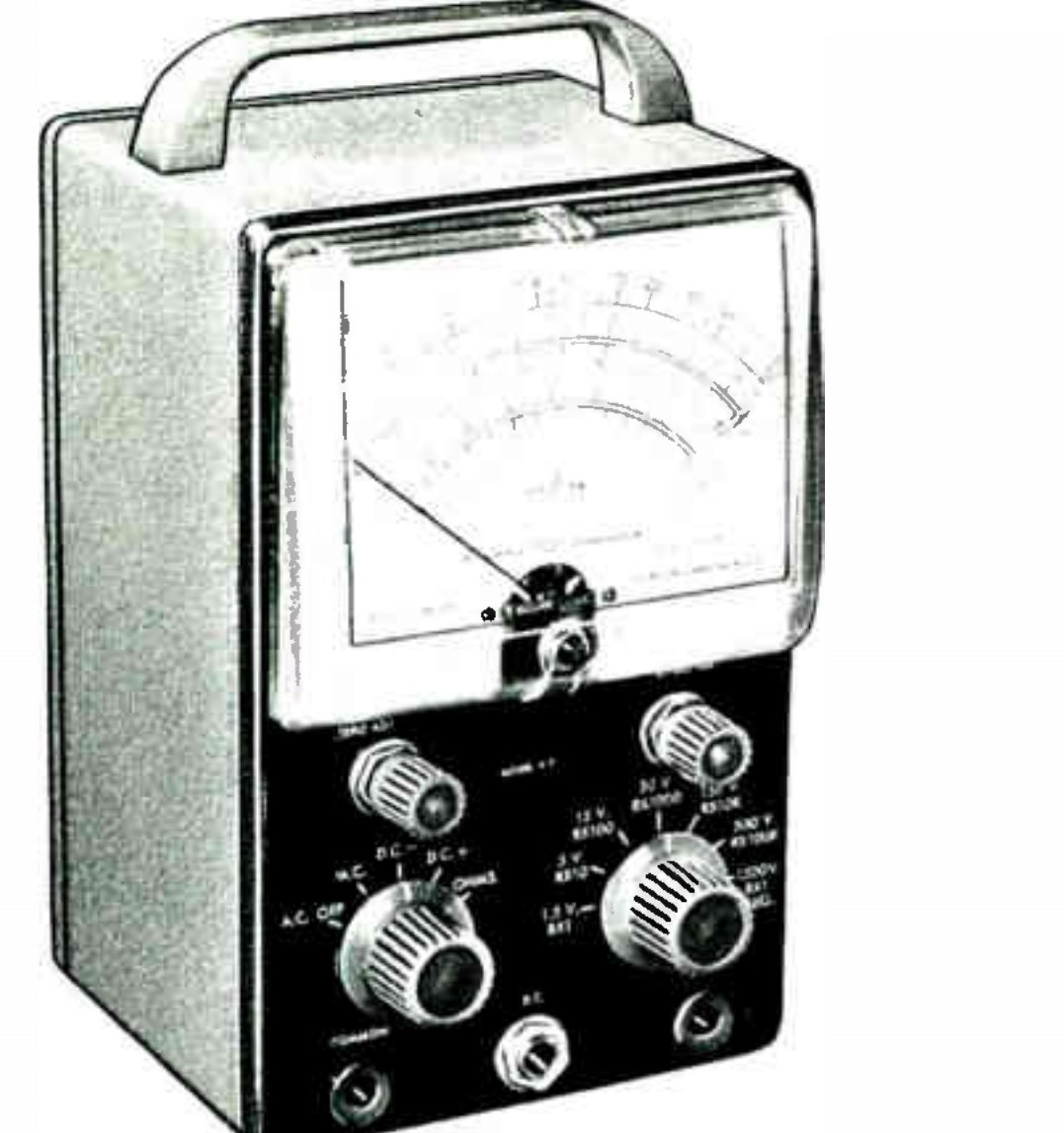
This volume covers the whole family as one dive: the V-series of 1947–1961, the IM-series table-top models that followed, the larger “Deluxe Service Bench” line that ran in parallel from 1961, and the solid-state instruments that eventually displaced them. The Heath Company’s own story — Benton Harbor, Daystrom, Schlumberger, Zenith and the end of the kits — is told in the site history dive and is not repeated here.
1.1 What a VTVM is, and why it mattered
An ordinary moving-coil multimeter measures voltage by drawing current through its own movement. A 20,000 ohms-per-volt meter on its 3-volt range presents 60,000 ohms to the circuit; across the grid resistor of a receiver’s detector stage that is enough to change the very voltage being measured. The vacuum-tube voltmeter solves the problem by putting a tube between the probe and the meter. The tube’s grid draws no appreciable current, so the instrument’s input resistance is set by a resistor chain rather than by the movement. Heath’s design, from the V-1 onward, presented 11 megohms on every DC range — 10 megohms in the divider chain inside the instrument, plus a further 1 megohm built into the tip of the DC probe to isolate the circuit under test from the capacitance of the test lead (Eckweiler, Heathkit of the Month #19).
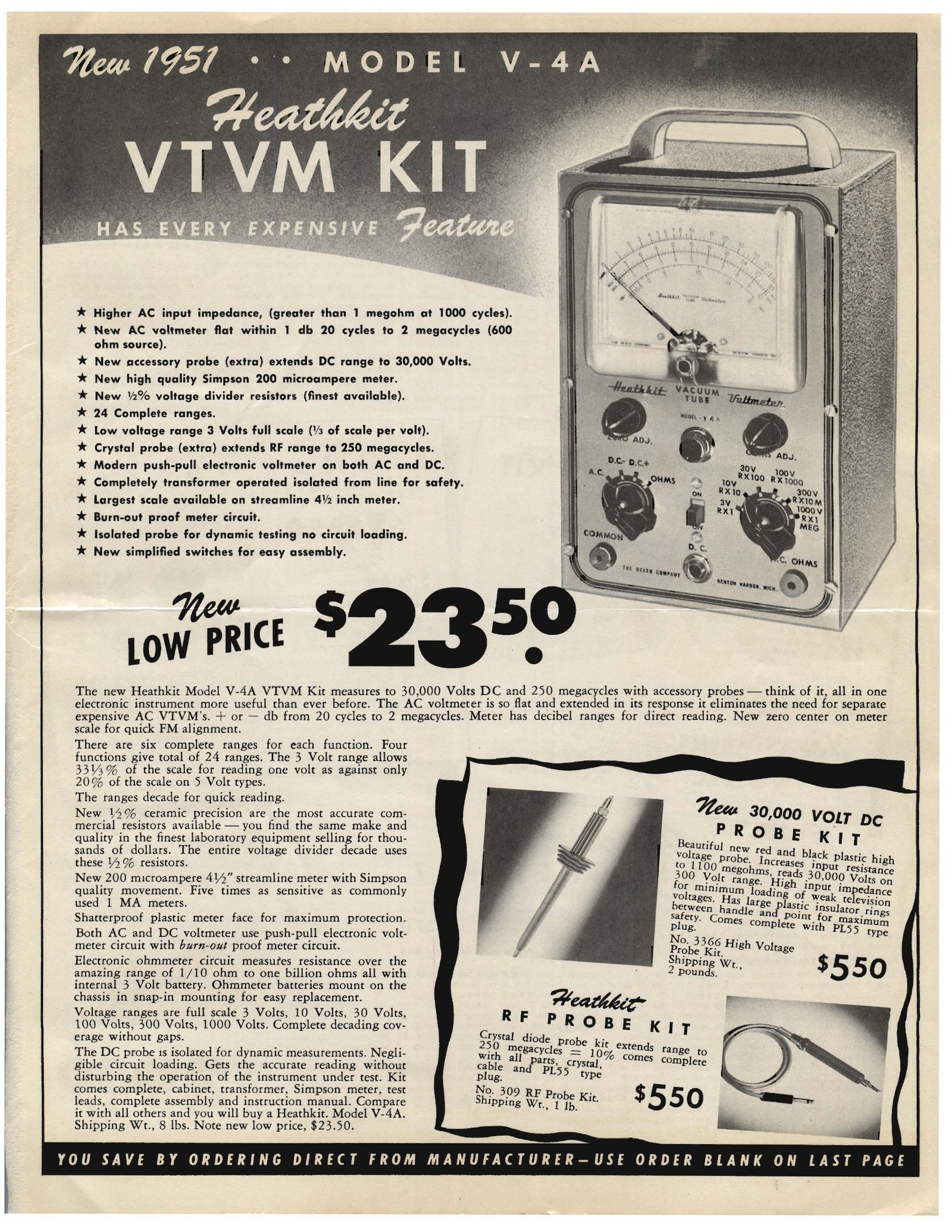
On the 1.5-volt range that works out to 7,333,333 ohms per volt, a figure Heath printed in its specifications for thirty years. A second advantage follows from the same architecture: the tube limits how much current can reach the movement, so a stray 400 volts applied while the range switch is set to 1.5 volts bends the pointer against its stop rather than burning the coil. Heath advertised this from the beginning as a “burn-out proof meter circuit” (Heath flyer, September 1950).
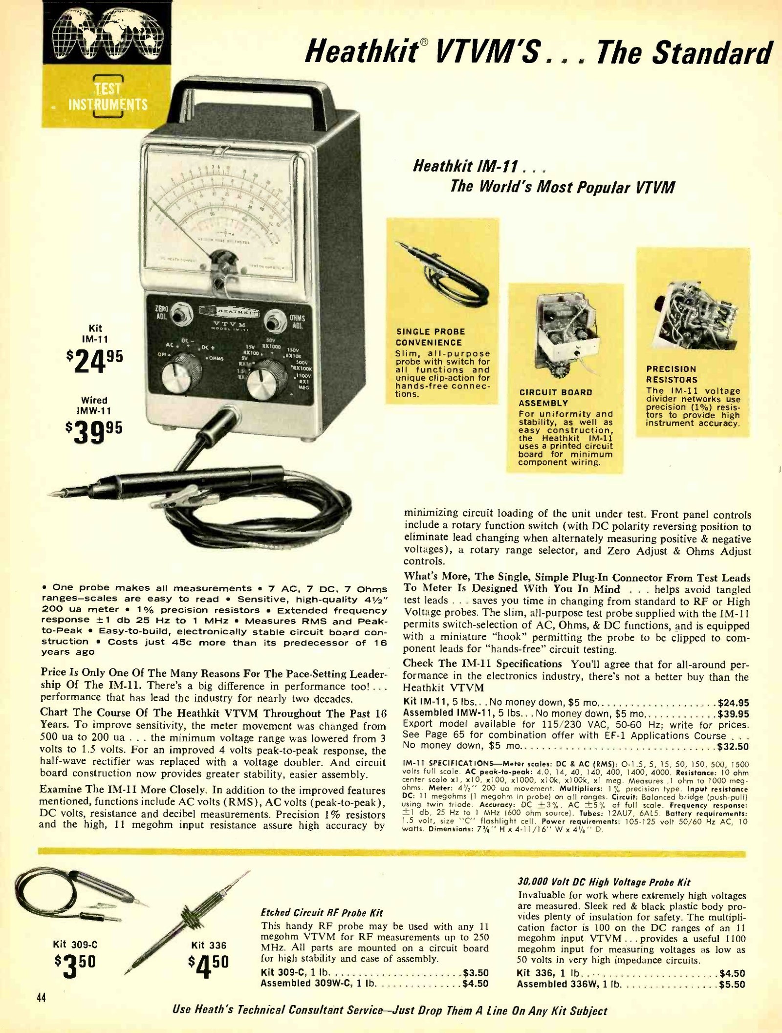
The instrument’s weakness is equally structural. The AC ranges work by rectifying the input, and a rectifier is neither linear nor free of contact potential; the AC input impedance is about 1 megohm rather than 11, and the useful frequency range stops around 1 MHz. Heath’s answer was an accessory: the 309-series RF probe, which rectified at the probe tip and let the same instrument read RF to 250 MHz (Eckweiler, Heathkit of the Month #118).
1.2 Where the voltmeter sat in the Heath line
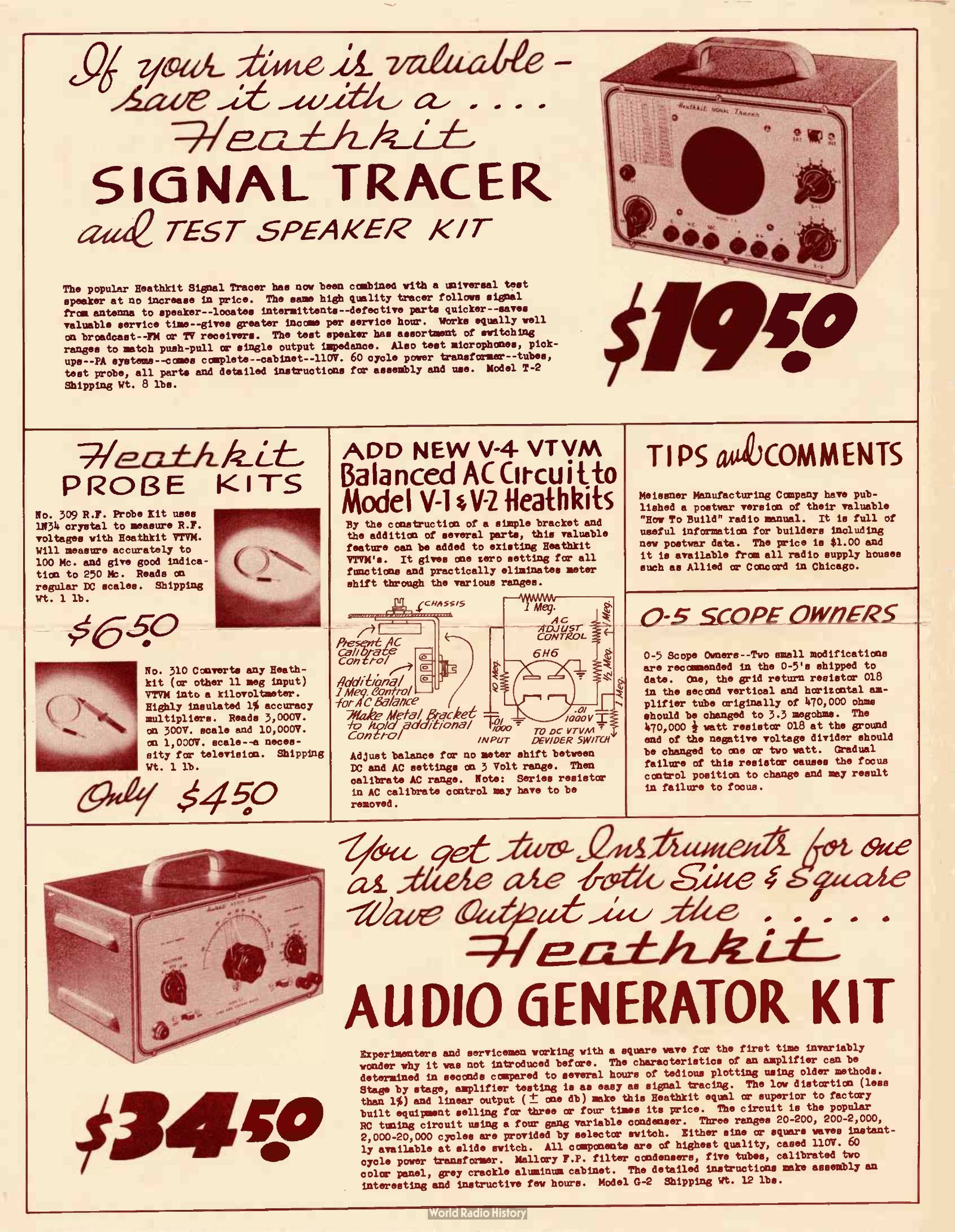
The O-1 oscilloscope of July 1947 was Heath’s first electronic kit. The voltmeter was the second. Bjorn Heyning, the engineer Howard Anthony brought back in October 1947, was handed the job, and the calibration scheme he and Anthony argued over — measure a fresh dry cell for the DC standard and the household mains for the AC standard — survived in every Heath voltmeter manual for the next four decades. Carl Helber remembered Anthony calling the VTVM his favourite kit, the one the company would go on selling as long as he was around (Heyning and Helber, Heath Stories; the episode is covered in volume 2 of the history dive).
He was right about the longevity. Charles Gilmore, who spent his career at Heath, named the VTVM and the HN-31 “Cantenna” dummy load as the company’s two lifetime volume leaders, and dated the last VTVM sale to 1989 (Gilmore, Electronic Design). Chuck Penson’s often-quoted figure of more than two million Heathkit VTVMs sold (Penson, QST, April 1997) covers the whole family across forty-two years; no production records survive to confirm it, and it should be read as an order of magnitude rather than a count. What the catalogues do support is Heath’s own claim, printed in 1962, that the IM-11 was “the world’s largest selling VTVM” (Fall–Winter 1962–63 catalogue; the scan is filed under 1963).
1.3 The lineage
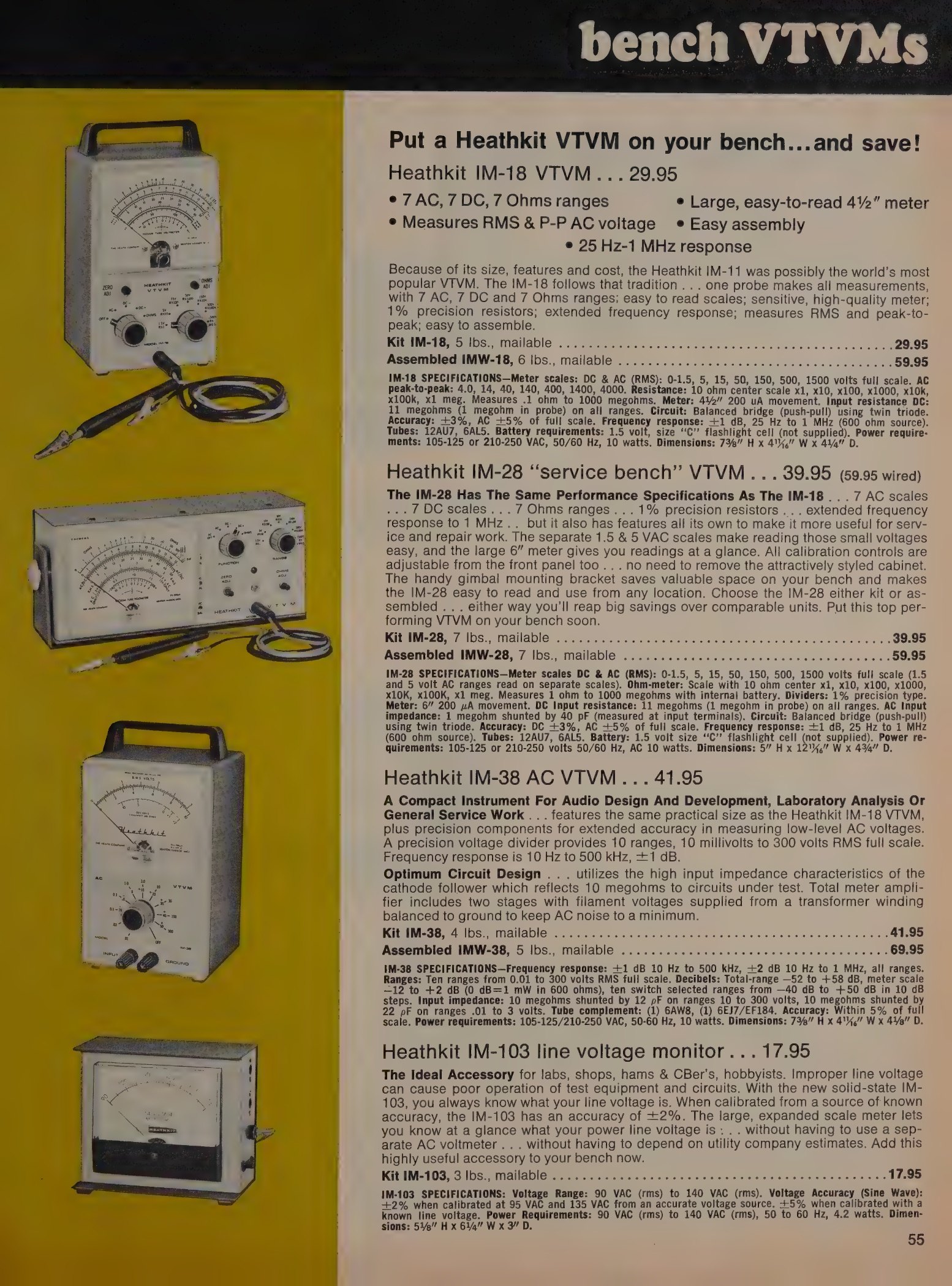
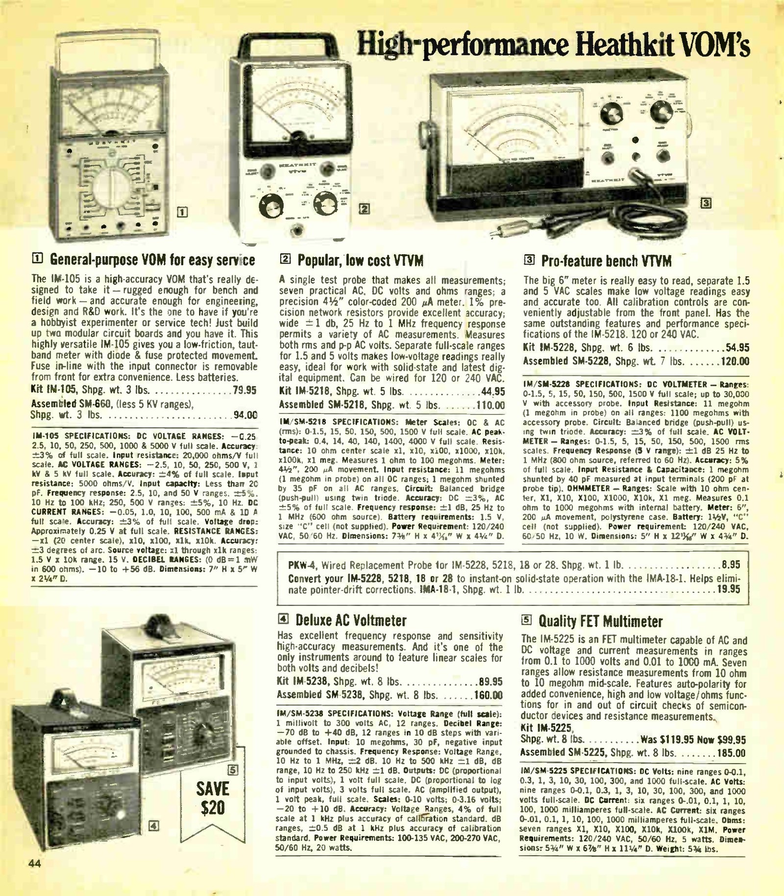
Three parallel lines share the same amplifier. The table-top series is the familiar one: a portable case with a 4½-inch meter, sold as V-1 through V-7A and then IM-11, IM-18 and IM-5218. The Deluxe Service Bench series, from 1961, put the same circuit behind a 6-inch meter in a bench cabinet: IM-10, IM-32, IM-13, IM-28, IM-5228. A third line, the AC VTVMs (AV-1, AV-2, AV-3, IM-21, IM-38, IM-5238), amplified the signal before rectifying it and is a different instrument with a shared surname; it is noted here for completeness and is not covered in detail.
Dates below follow Bob Eckweiler’s two survey articles. His 2022 table for the pre-1961 models is built from Heath’s advertisements in Radio News and Radio & Television News and gives month-level precision; his 2009 article on the V-7A gives slightly different, looser dates for the same models. Where the two disagree, both are shown, and catalogue scans are cited where they settle the question.
Table 1 — The lineage
| Model | In the line | Kit price | Principal change |
|---|---|---|---|
| V-1 | Dec 1947 – early 1949 | $24.50 | The original: five ranges, 6X5 rectifier, 6H6 AC converter, 6SN7 bridge, two cells for the ohmmeter |
| V-2 | 1949 | $24.50 | Sixth range added; 200 µA movement in place of 500 µA |
| V-2A | late 1949 | $24.50 | Short-lived revision |
| V-3 | advertised Apr–May 1949 | $34.50 announced | Battery-operated version; few if any built |
| V-4 | Jan 1950 | $24.50 | Larger meter; selenium rectifier replaces the 6X5; AC balance control added |
| V-4A | late 1950 – 1951 | $23.50 | AC converter revised back toward the V-1 circuit; ½% divider resistors advertised |
| V-5 | Sep 1951 | $24.50 | Formed-aluminium cabinet, 4½-inch meter; 12AU7 replaces 6SN7; loctal 7A6 AC converter; single 1.5 V cell |
| V-5A | 1952 | $24.50 | 7A6 abandoned; back to the 6H6 |
| V-6 | Sep 1952 – 1954 | $24.50 | Seven ranges, 1.5 V to 1500 V; R×100K added; heavier power-supply filter |
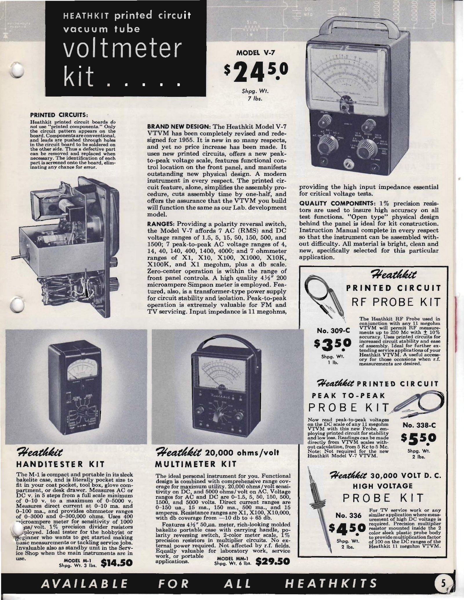
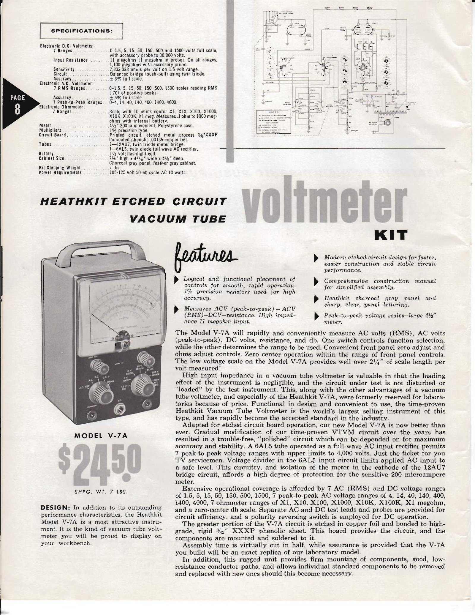
| V-7 | autumn 1954 – 1955 | $24.50 | First Heathkit with a printed circuit board; 6AL5 voltage-doubler AC circuit; peak-to-peak scales; charcoal-grey panel |
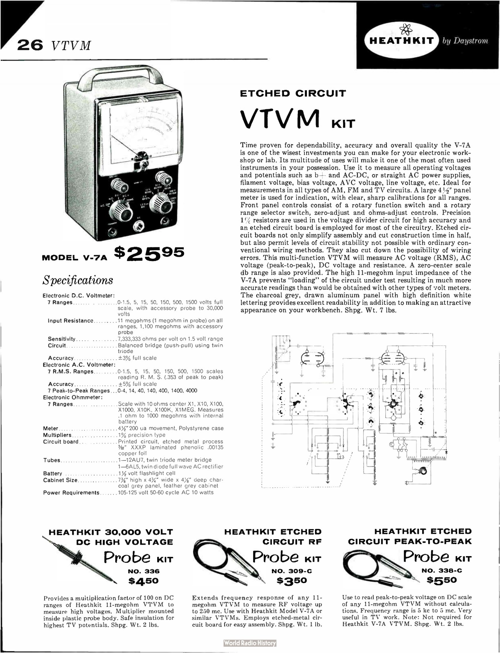
| V-7A | 1955/56 – 1961 | $24.50, later $25.95 | Thicker circuit board (see below); otherwise as the V-7 |
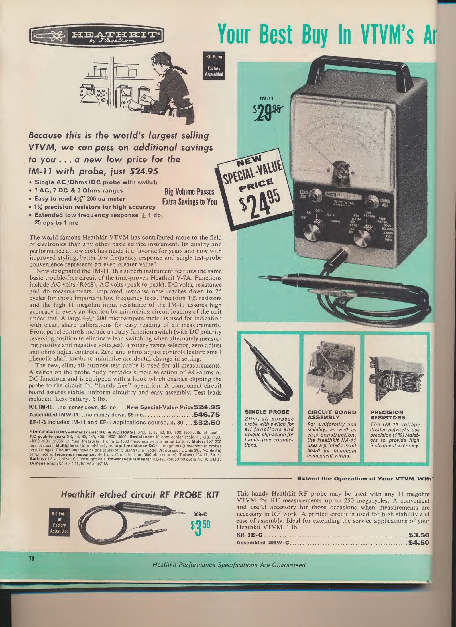
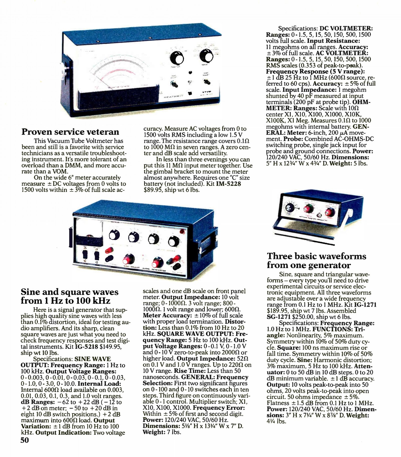
| IM-11 | 1961 – 1969 | $24.95, later $29.95 | Same circuit, new cabinet and panel; single switching probe; response extended down to 25 Hz |
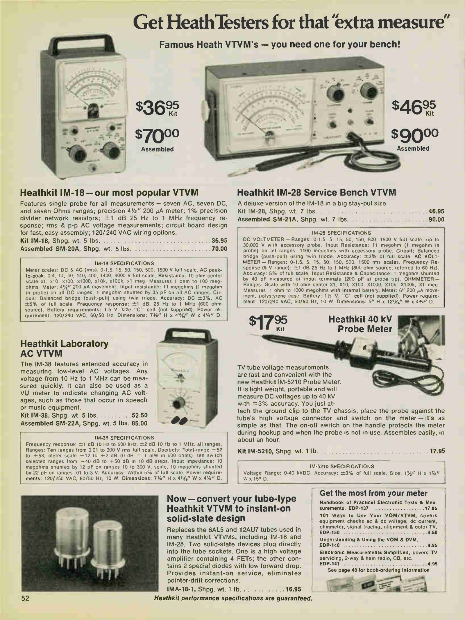
| IM-18 | 1969 – 1977 | $29.95 – $36.95 | ”New look” styling; dual-primary transformer for 120/240 V |
| IM-5218 | 1977 – 1983 | $44.95 – $49.95 | ”Post new look” styling; the last table-top VTVM |
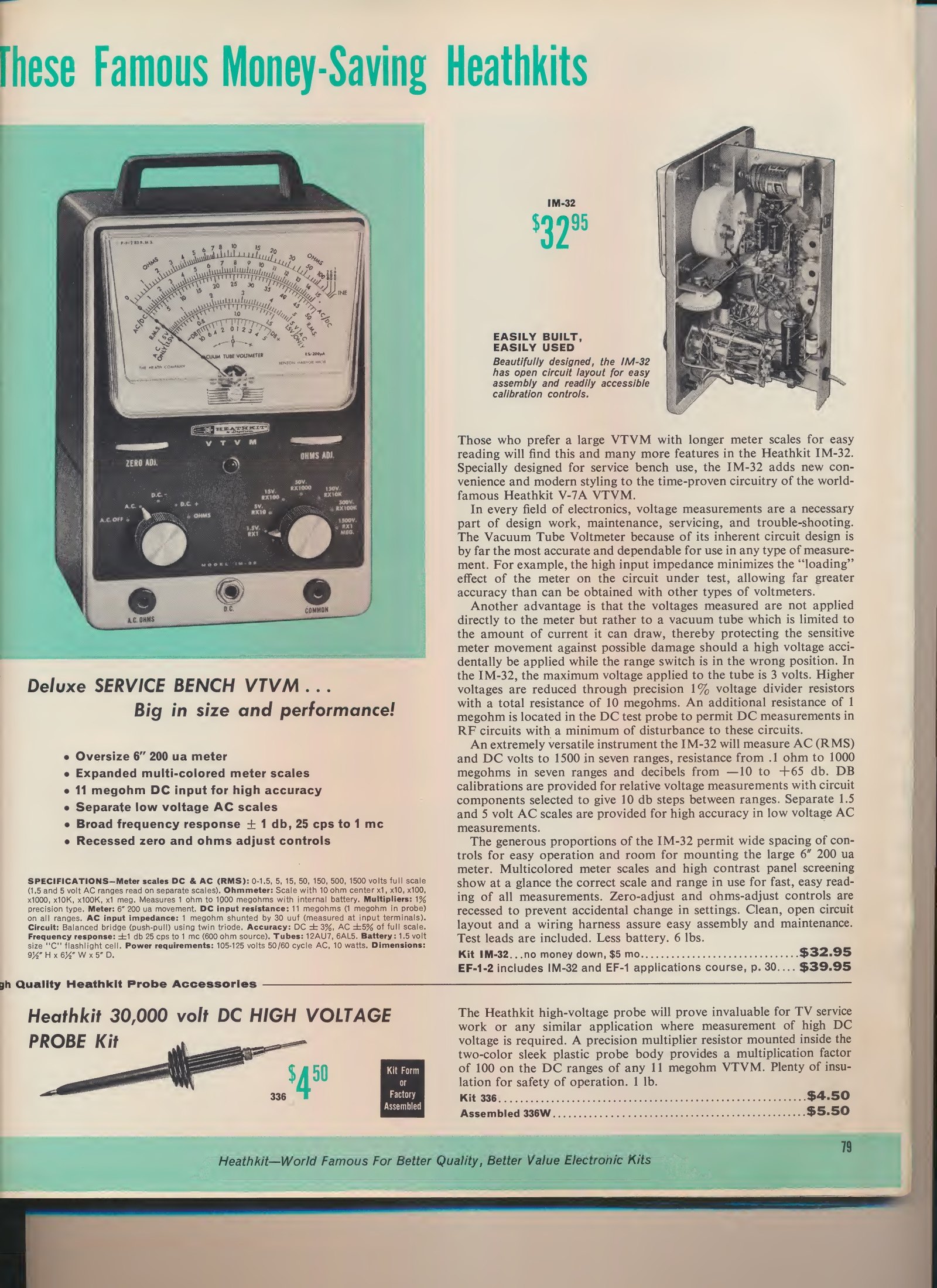
| IM-10 | 1961 – 1962 | $32.95 | First bench model: 6-inch meter, vertical cabinet, √10 range ratios, separate low-voltage AC scales |
| IM-32 | 1962 – 1963 | $32.95 | IM-10 restyled; silicon rectifier still to come |
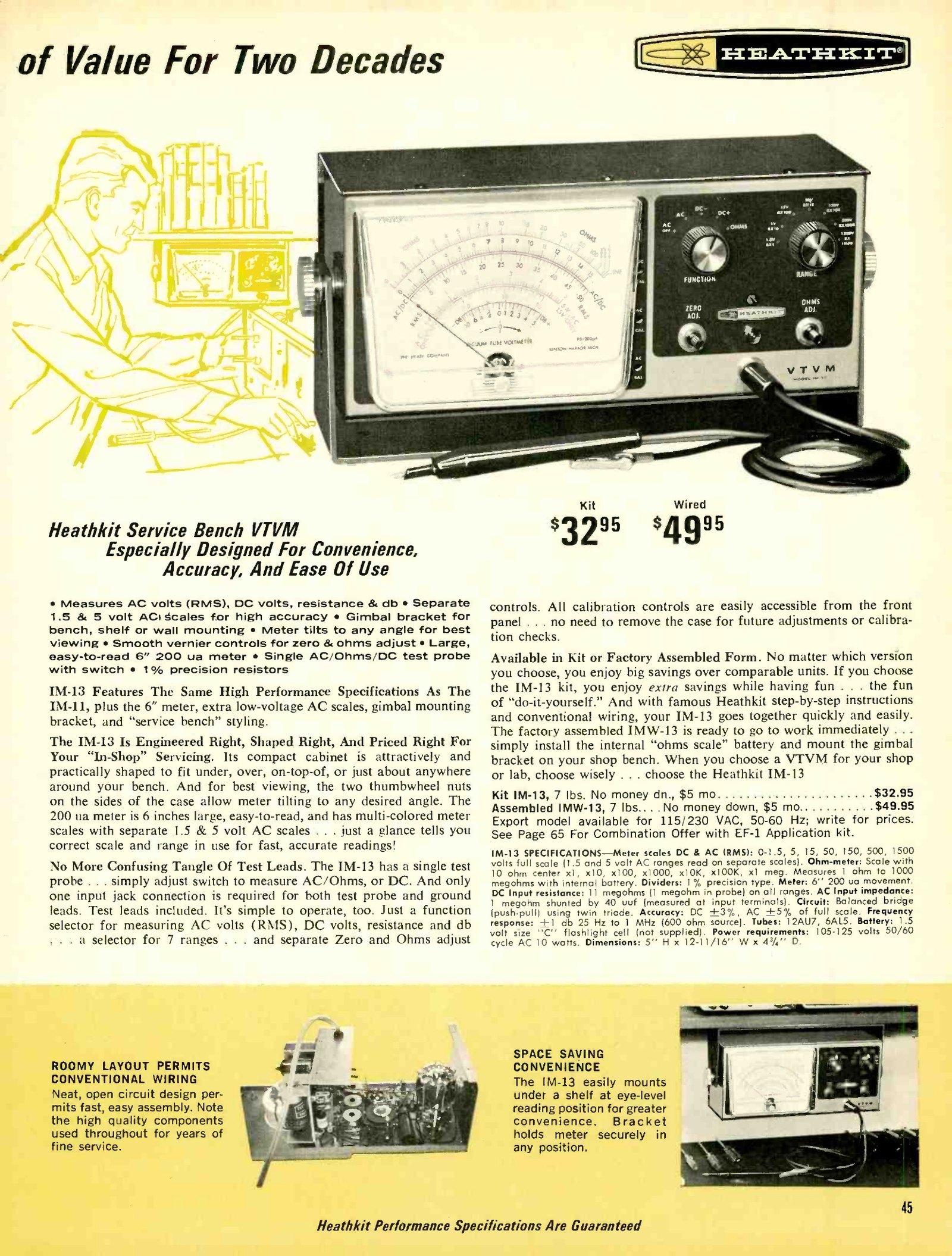
| IM-13 | 1963 – 1969 | $32.95 – $36.50 | Horizontal cabinet, gimbal bracket, front-panel calibration access, silicon rectifier, neon pilot |
| IM-28 | 1969 – 1977 | $39.95 – $46.95 | IM-13 restyled; dual-primary transformer and three-wire cord |
| IM-5228 | 1977 – 1989 | $54.95 – $129.95 | Final restyle; the last Heathkit vacuum-tube voltmeter |
Sources: Eckweiler #110, Table 1 and #19 for models and dates; prices from the catalogue scans cited through this dive.
Two derived model numbers appear on the same instruments. A W inserted in the number — IMW-11, IMW-13, IMW-28 — marks a factory-wired unit, always sold at roughly twice the kit price. From the mid-1970s Schlumberger’s instrument division rebranded the wired versions again, as SM-20A, SM-21A, SM-5218 and SM-5228 (Spring 1976 catalogue; Eckweiler #110).
1.4 Three turning points
1954–55: the printed circuit. The V-7 is the instrument usually named as the first Heathkit built on a printed circuit board, and the manuals bear that out: the V-7’s own introduction calls it “the first kit instrument using a prewired, prefabricated printed circuit board in its design” (V-7 assembly manual). Heath told buyers the board cut construction time in half, and worried internally that it would spoil the experience of building. Gilmore recalled that “there were many at Heath who questioned this move, concerned a PCB would ‘ruin’ the kit building experience. Clearly this wasn’t the case” (Gilmore). The Winter 1955 flyer advertised the V-7 with a panel of explanatory copy about what a printed circuit was and was not: the board carried only the wiring pattern, not printed components, and parts could still be unsoldered and replaced.
1961: the IM prefix and the bench model. In 1961 Heath restyled its test equipment and renumbered it. The V-7A became the IM-11 with a new cabinet, a single switching probe in place of three leads, and a low-frequency response extended from 42 Hz down to 25 Hz; the circuit was otherwise the V-7A’s. In the same year the company introduced a second, larger instrument aimed at the television service trade — the IM-10, with a 6-inch meter, separate scales for the two lowest AC ranges, and range multipliers chosen so that adjacent ranges differ by exactly √10, which makes the decibel scale read correctly across range changes (Eckweiler #110).
1967–77: the transistor arrives, and the tubes stay. Heath’s first solid-state voltmeter, the IM-17 “utility solid-state voltmeter”, was introduced late in 1967 at $25.95 and sold for a decade; it used five transistors and an FET-like high-impedance input to give the same 11 megohms on DC without tubes (Eckweiler #78). The IM-16 solid-state volt-ohm meter followed with a 6-inch meter and battery or line operation at $54.95 (1972 catalogue). Neither killed the tube instruments: the 1972 catalogue sells the IM-17, IM-16 and IM-25 solid-state meters on one spread and the IM-18 and IM-28 VTVMs on the next. Heath even sold a kit to convert the old instruments — the IMA-18-1, a pair of plug-in cans containing four FETs and two diodes that replaced the 12AU7 and 6AL5 and gave instant-on operation, $19.95 in 1978.
1.5 The V-7A board: what actually changed
The difference between the V-7 and the V-7A is a single line in the specifications, and it has been reported incorrectly. Brueschke and Mack’s history states that the V-7’s 1/8-inch board was prone to breakage and that the V-7A’s board was made 50 per cent thicker, at 3/32 inch (Brueschke and Mack, AWA Review vol. 32, p. 146). Those two numbers cannot both be right: 3/32 inch is thinner than 1/8 inch.
The manuals settle it. The V-7 manual specifies “printed circuit, etched metal process 1/16″ XXP laminated phenolic .00135 copper foil” (V-7 assembly manual, p. 2). The V-7A manual, identical in almost every other respect, specifies 3/32″ (V-7A assembly manual, p. 2), and the 1956 and 1959 catalogues print the same 3/32″ figure for the V-7A. The change was therefore from 1/16 inch to 3/32 inch — exactly the 50 per cent increase Brueschke and Mack describe, applied to a starting thickness they mis-stated. Eckweiler, who does not give figures, says only that the V-7A is believed identical to the V-7 “with the exception of the circuit board which was improved significantly” (#19). Heath’s board carried the part number 85-1, the first in a series that ran to the end of the company.
The dating of the two models is less tidy. Eckweiler’s advertisement-derived table puts the V-7 in the catalogue from September 1954 to August 1955 and the V-7A from September 1955; his earlier article places the V-7 in early 1955 and the V-7A “about a year” later, in production from 1956 into 1962; Brueschke and Mack date the V-7A to 1955 and give its run as 1955–1961. The catalogue scans bracket the change: the Winter 1955 and Fall 1955 flyers both show the V-7, and the 1956 catalogue shows the V-7A. The V-7A manual carries a 1960 copyright and a 6/30/61 print date on its latest printing, which tells only when that edition was run.
1.6 Who bought them
The audience shifted three times. The V-1 and V-2 were sold to the postwar experimenter who was also being offered war-surplus condensers by the truckload; the flyers of 1949 and 1950 sit voltmeter advertisements beside surplus lists. By the mid-1950s the buyer was a television service technician — the peak-to-peak scales added with the V-7 exist because television circuits are full of non-sinusoidal waveforms whose RMS reading means nothing, and the Fall 1955 flyer says so directly: “just the thing you TV servicemen have needed”. The IM-13’s 1967 catalogue copy is addressed to a shop owner, offering a gimbal bracket so the meter can hang under a bench shelf, and the bench series’ extra red scales exist because the rectifier reads low on the two lowest AC ranges and a service bench cannot afford that error.
The third audience was the radio amateur, and it is the one that kept the instrument alive longest. A VTVM and an RF probe were, between them, most of what was needed to align a Heathkit transmitter or receiver after building it (Eckweiler #19). Long after digital multimeters were cheap, the VTVM’s immunity to RF fields and its stable, driftless zero kept it on amateur benches. Heath went on selling the IM-5228 through the 1980s to that audience, at $79.95 in 1983 and $89.95 in 1987, against its own digital multimeters at similar money.
1.7 Headline specification
The figures below are the V-7A’s, and with two exceptions they are also the IM-11’s, the IM-18’s and the IM-5218’s. Full specifications for every model, including the bench series, are in the reference volume.
Table 2 — Headline specification
| DC ranges | 0–1.5, 5, 15, 50, 150, 500, 1500 V full scale; to 30,000 V with accessory probe |
| DC input resistance | 11 MΩ on all ranges (1 MΩ of it in the probe); 1100 MΩ with the high-voltage probe |
| DC sensitivity | 7,333,333 ohms per volt on the 1.5 V range |
| DC accuracy | ±3% of full scale |
| AC ranges (RMS) | 0–1.5, 5, 15, 50, 150, 500, 1500 V |
| AC ranges (peak-to-peak) | 0–4, 14, 40, 140, 400, 1400, 4000 V |
| AC accuracy | ±5% of full scale |
| AC frequency response | ±1 dB, 42 c/s to 7.2 Mc on the V-7A; ±1 dB, 25 Hz to 1 MHz from the IM-11 onward |
| AC input impedance | about 1 MΩ shunted by 35–40 pF |
| Ohms ranges | ×1, ×10, ×100, ×1000, ×10K, ×100K, ×1 MEG; 10 Ω centre scale; 0.1 Ω to 1000 MΩ |
| Meter | 4½-inch, 200 µA movement (6 inch on the bench models) |
| Tubes | 12AU7 twin triode meter bridge; 6AL5 twin diode AC rectifier |
| Battery | one 1.5 V cell for the ohmmeter |
| Power | 105–125 V, 50–60 c/s, 10 W (120/240 V from the IM-18 and IM-28) |
| Size and weight | 7⅜ × 4 11/16 × 4⅛ inches; 7 lb shipping |
Source: V-7A assembly manual and the 1959, 1962–63 and 1976 catalogues.
Sources
- Eckweiler, Bob (AF6C). “Heathkit of the Month #19: V-7A VTVM.” RF, Orange County Amateur Radio Club, December 2009. https://www.w6ze.org/Heathkit/Heathkit_019_V7a.pdf
- Eckweiler, Bob (AF6C). “Heath of the Month #110: Heathkit ‘Deluxe Service Bench’ VTVMs.” RF, 2022. https://www.w6ze.org/Heathkit/Heathkit_110_DSB_VTVMs.pdf
- Eckweiler, Bob (AF6C). “Heath of the Month #78: IM-17 Utility Solid-State Voltmeter.” https://www.w6ze.org/Heathkit/Heathkit_078_IM17.pdf
- Eckweiler, Bob (AF6C). “Heath of the Month #118: Heathkit Probes, Part I.” https://www.w6ze.org/Heathkit/Heathkit_118_Probes_I.pdf
- Brueschke, Ernest E., and Mack, Donald F. “The History of the Heath Companies.” AWA Review vol. 32 (2019). https://archive.org/details/thehistoryoftheheathcompanies
- Gilmore, Charles. “Heathkit: An Employee’s Look Back.” Electronic Design, 30 November 2020. https://www.electronicdesign.com/blogs/contributed-blogs/archive/communiqu/article/21148923/electronic-design-heathkit-an-employees-look-back
- Penson, Chuck (WA7ZZE). “Heathkit: A Guide to the Amateur Radio Products,” summarised at the Heathkit Virtual Museum. https://heathkit-museum.com/hkarticle1.html
- Heathkit assembly manuals, Model V-7 (595-90), V-7A (595-110), IM-11 (595-486), IM-18 (595-1154), IM-5218 (595-1972), via the Internet Archive. https://archive.org/details/manualsplus_08096 · https://archive.org/details/heathkitmanualva00unse · https://archive.org/details/heathkitassembly00unse_7 · https://archive.org/details/heathkitassembly00unse_4 · https://archive.org/details/IM-5218-manual
- Heath Company catalogues and flyers, 1947–1991, scanned at World Radio History. https://www.worldradiohistory.com/Archive-Catalogs/Heathkit_Catalogs.htm
Comments (0)