Vacuum Tube Voltmeters · Volume 4
Calibration and Use
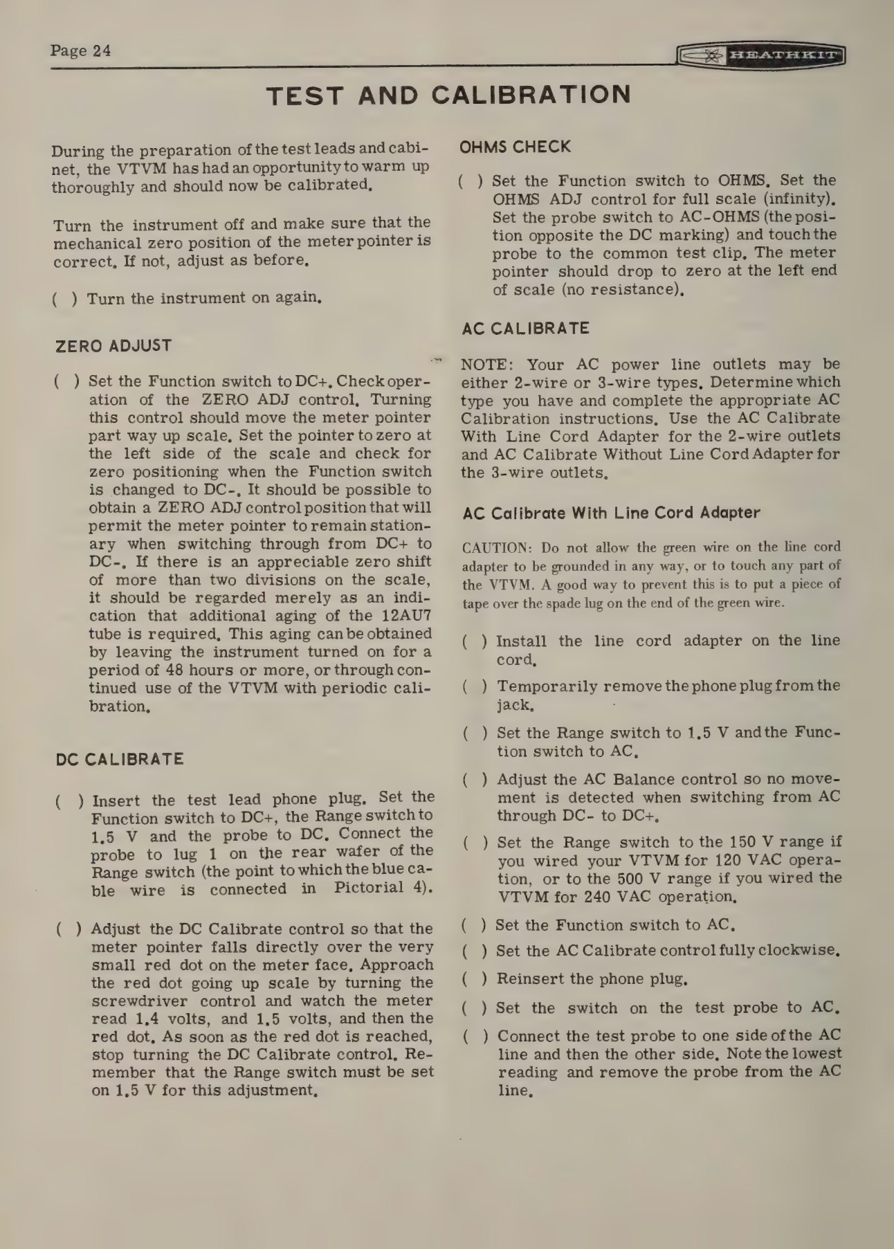
Heath’s answer to the question of how a customer calibrates a precision instrument he has just built at his kitchen table was settled in 1947 and never changed: use a fresh dry cell as the DC standard and the household mains as the AC standard. Bjorn Heyning thought it inadequate when Howard Anthony proposed it, and said so; Anthony’s reply was that it would get the customer started, and that anyone who needed better could borrow a standard. Heyning’s verdict forty years later was that “history proved that he was right, for that idea worked without fault for many years” (Heyning, Heath Stories). Rich Post notes that Heath printed a small red dot on the meter scale at the voltage of a fresh carbon-zinc cell, which gave a builder with no instruments at all about 3 per cent accuracy (Post, “The Heathkit Legacy”).
4.1 The calibration procedure
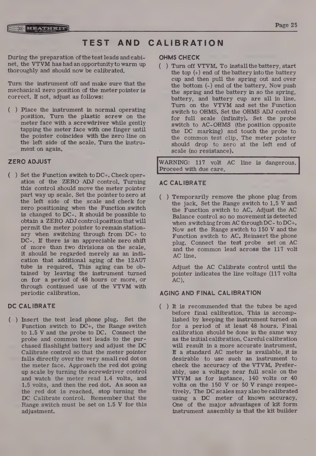
The sequence below is the one printed in the IM-11 and IM-18 manuals; the V-7A’s differs only in wording. It is given here in outline, as a description of what the instrument needs rather than as a substitute for the manual, which should be to hand for any actual work.
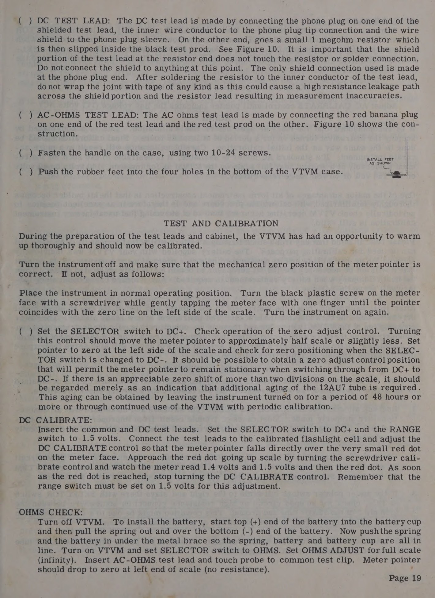
1. Warm up and check the zero. With the function switch on DC+, the ZERO ADJUST control should bring the pointer to the left-hand zero, and switching to DC− should not move it by more than about two scale divisions. A larger shift is not a fault: it means the 12AU7 has not yet settled.
2. DC calibrate against a battery. With the range switch on 1.5 V, the function switch on DC+ and the probe switched to DC, the probe is touched to a fresh 1.5-volt carbon-zinc cell and the internal DC CALIBRATE control adjusted until the pointer sits exactly on the small red dot printed just past 1.5 on the scale. The dot corresponds to 1.55 volts, the open-circuit voltage of a fresh zinc-carbon cell. The manuals insist the dot be approached from below. An alkaline cell must not be used for this: its fresh voltage is higher and varies between makers (Eckweiler, Heathkit of the Month #110).
3. Check the ohms function. With the function switch on OHMS, the OHMS ADJUST control should be able to drive the pointer to full scale with the leads open, and the ZERO ADJUST to bring it to zero with them shorted. There is no ohms calibration: accuracy comes from the 1 per cent resistors in the chain.
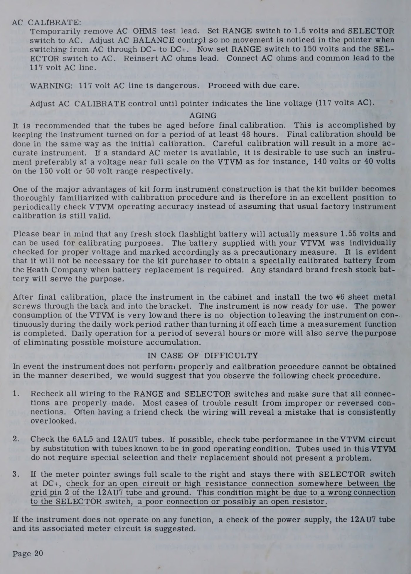
4. AC balance and AC calibrate against the line. The AC BALANCE control is set so that the pointer does not move when switching between AC, DC− and DC+ on the 1.5 V range. The AC CALIBRATE control is then set while measuring the AC line itself — nominally 117 volts — with the range switch on 150 V, or on 500 V if the instrument is wired for 240-volt mains.
5. Age the tubes and do it again. The instrument is left switched on for at least 48 hours and then calibrated a second time. The IM-11 manual makes a point of this being an advantage of kit ownership: the builder “becomes thoroughly familiar with the calibration procedure and is therefore capable of periodically checking VTVM operating accuracy, instead of assuming that usual factory instrument calibration is still valid.”
4.2 The one genuinely dangerous step
Calibrating against the mains means deliberately connecting a test probe to a live outlet, and the instrument’s common lead is bonded to its chassis. On a two-wire instrument with a polarised or unpolarised plug, a reversed connection puts the chassis at line potential; on a three-wire instrument, connecting the common lead to the live side short-circuits the supply through the safety earth.
Heath’s own instructions handle this by having the builder identify the neutral side first — connect the probe to one side of the line, then the other, and take the lower reading as the grounded side — and by warning, in the later manuals, never to use the common lead when measuring line voltage at all. Eckweiler is blunter: reversing the leads on an IM-10 or IM-32 blows the instrument’s internal fuse, on an IM-28 or IM-5228 it will probably blow the house fuse and damage the instrument, and on an unfused IM-13 it can put the chassis at line potential with the operator touching it, which he describes as “possibly fatal”. His recommendation is to do the AC calibration through an isolation transformer, measuring on the transformer’s output side, or against a known-good AC voltmeter (#110).
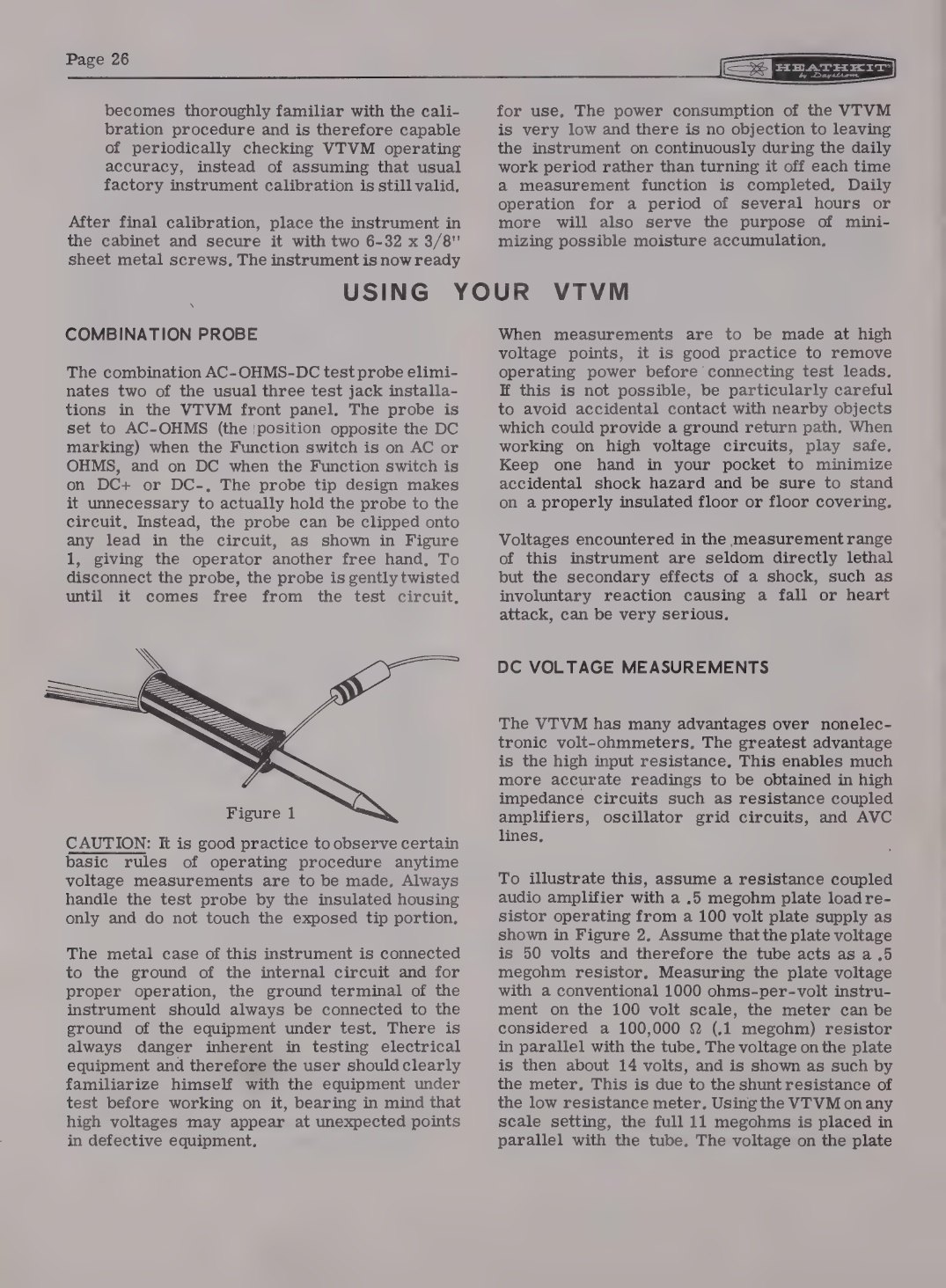
The instrument’s own manual is equally direct about high-voltage work generally: remove power before connecting the leads where possible, keep one hand in a pocket, stand on an insulated floor, and remember that “high voltages may appear at unexpected points in defective equipment”. The IM-11 manual adds a sentence that reads oddly at first and is exactly right: the voltages this instrument measures “are seldom directly lethal but the secondary effects of a shock, such as involuntary reaction causing a fall or heart attack, can be very serious.”
4.3 Using it on the bench
Selecting a function. The function switch reads OFF, AC, DC−, DC+, OHMS. The two DC positions reverse the meter connections internally, which is the reason the instrument has no polarity-reversing lead: a negative bias line and a positive supply rail can be measured one after the other without moving anything but the switch.
Selecting a range. Highest range first if the voltage is unknown, then down. The ranges step 1.5, 5, 15, 50, 150, 500, 1500, and the 1.5-volt range gives over two and a quarter inches of scale per volt on a 4½-inch meter — one of the things the catalogue copy kept pointing at.
Reading the scales. Black for DC and AC RMS, red on the bench models for the two lowest AC ranges, green for ohms, and a separate decibel scale referenced to 1 milliwatt in 600 ohms. The peak-to-peak scales — 4, 14, 40, 140, 400, 1400, 4000 — are read directly; the RMS scales are the same reading multiplied by 0.353 and are therefore only correct for a sine wave.
Centre-zero. The zero-adjust control has enough range to place the pointer at mid-scale in one of the two DC positions, though not usually in both. The V-7A manual gives its purpose precisely: a null indicator for discriminator adjustment, for bias measurements, and anywhere polarity may reverse. That single feature is why the instrument was standard equipment for FM and television alignment.
Measuring resistance. Choose the range that puts the reading near mid-scale, set full scale with the leads open, set zero with them shorted, then measure. The half-scale point equals the range resistance, which is why the green scale is marked 10 at its centre. With the leads open the instrument reads infinity; a meter that cannot be brought to full scale has a tired cell.
4.4 What it was actually used for
Heath’s own list of applications, printed beside the V-7A in the 1956 catalogue, is a good description of the instrument’s working life: measuring B+ in power supplies of every kind, filament voltage, bias voltage, AVC voltage and line voltage; measurements “in all types of AM, FM and TV circuits”; testing discriminator or detector operation and AVC or AGC performance; resistance tests and continuity (1956 catalogue).
Four of those jobs are the ones a VTVM does better than the alternatives of its day, and each maps onto a property of the circuit.
Grid and bias voltages. A grid return of several megohms cannot be measured with a 20,000 ohms-per-volt meter without changing the very voltage being read. The 11-megohm input is the point of the instrument.
AVC and AGC lines. These are high-impedance control voltages, often negative; the DC− position of the function switch reads them without swapping leads, and the centre-zero setting shows which way a control line is moving.
Discriminator alignment. An FM detector is aligned to a null that crosses through zero. The centre-zero facility exists for exactly this, and it is the reason the instrument sat on television and FM service benches rather than in a drawer.
Peak-to-peak waveforms in television circuits. Sync, blanking and sweep waveforms are not sinusoids, and their peak-to-peak value is what service data specifies. Heath added the scales with the V-7 in 1954 and sold the instrument on them for the rest of the decade.
Two jobs it does badly, and both are worth knowing. Audio and RF power levels beyond about 1 MHz need either the RF probe or a different instrument, because the AC section’s response stops there and its 1-megohm input loads the circuit. And any AC measurement of a non-sinusoidal waveform read on the RMS scale will be wrong — read peak-to-peak instead.
4.5 The probes are half the instrument
A Heathkit VTVM on its own measures DC to 1500 volts, AC to about 1 MHz and resistance to 1000 megohms. What it does beyond that depends entirely on what is screwed onto the end of the lead.
Table 1 — The probes are half the instrument
| Probe | Years | What it does | Price |
|---|---|---|---|
| 309, 309-A/B/C | from Jan 1949 | RF probe; rectifies at the tip. The 1949 version was advertised as accurate to 100 Mc with a useful indication to 250 Mc; the 309-C as accurate to 250 Mc within ±10 per cent | $6.50 (1949), $3.50 (1956, 1961) |
| 310 | from Jan 1949 | 10 kV high-voltage probe, ×10 multiplier | $4.50 (1949) |
| 336 | from mid-1950 | 30 kV high-voltage probe; 1090 MΩ resistor, ×100 multiplier, raising input resistance to 1100 MΩ | $4.50 (1956, 1961) |
| 338, 338-B/C | from 1952 | Peak-to-peak probe, 5 kHz–5 MHz | $6.50 (1952), $5.50 (1956) |
| PK-3, PK-3A | from early 1970 | RF probe for the later meters; banana-plug and phone-plug versions, and a positive output where the 309 gave a negative one | kit price not found; wired PKW-3 $7.00 (1972) |
| PKW-4 | from 1981 | Factory-wired replacement switching probe for the IM-18, IM-28, IM-5218 and IM-5228 | $10.95 (1980), $19.95 (1983) |
Sources: Eckweiler #118 and #119; prices from the catalogues of 1949, 1961, 1970, 1980 and 1983.
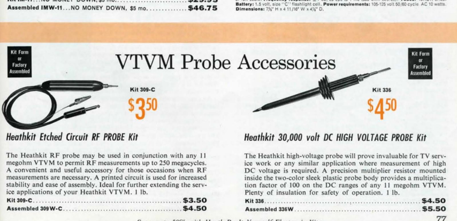
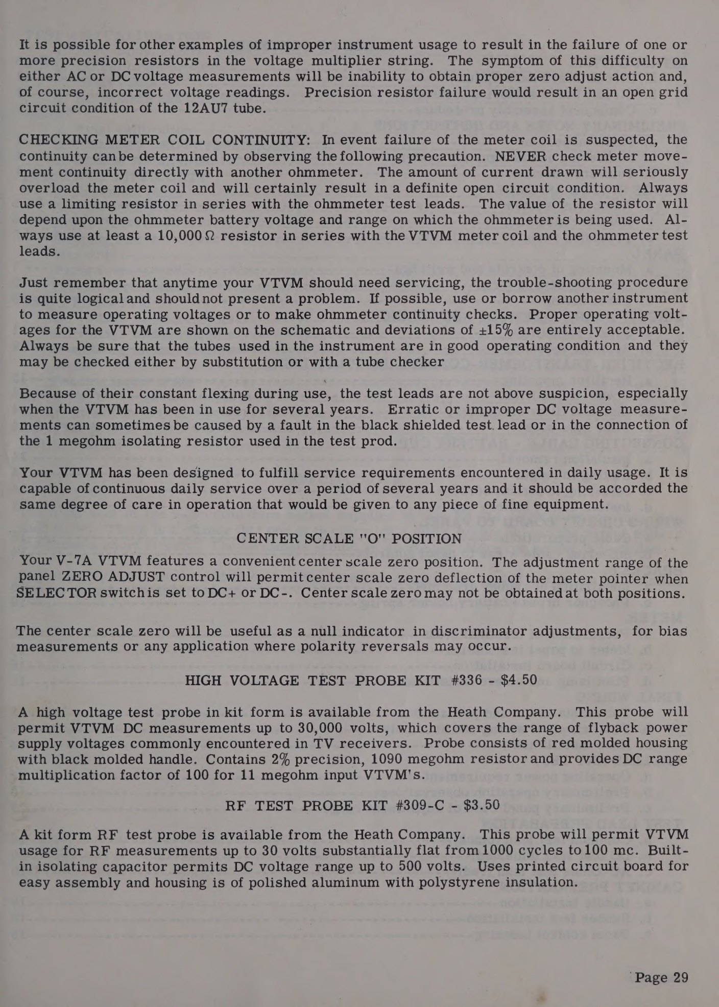
The RF probe matters more than its price suggests. The instrument’s AC section is limited to about 1 MHz and loads a circuit with roughly 1 megohm and 35 picofarads; the RF probe rectifies at the tip and presents a light load, which is what makes the same meter usable for aligning a transmitter or a receiver. Eckweiler’s summary of why an amateur owned a VTVM at all is that “a VTVM and RF probe were two of the few instruments needed to align or adjust the equipment after it was built” (#19). One caution carries over to modern use: the 309 series produces a negative DC output, so the function switch goes to DC−, while the later PK-3A produces a positive output and needs DC+.
4.6 Learning to use it
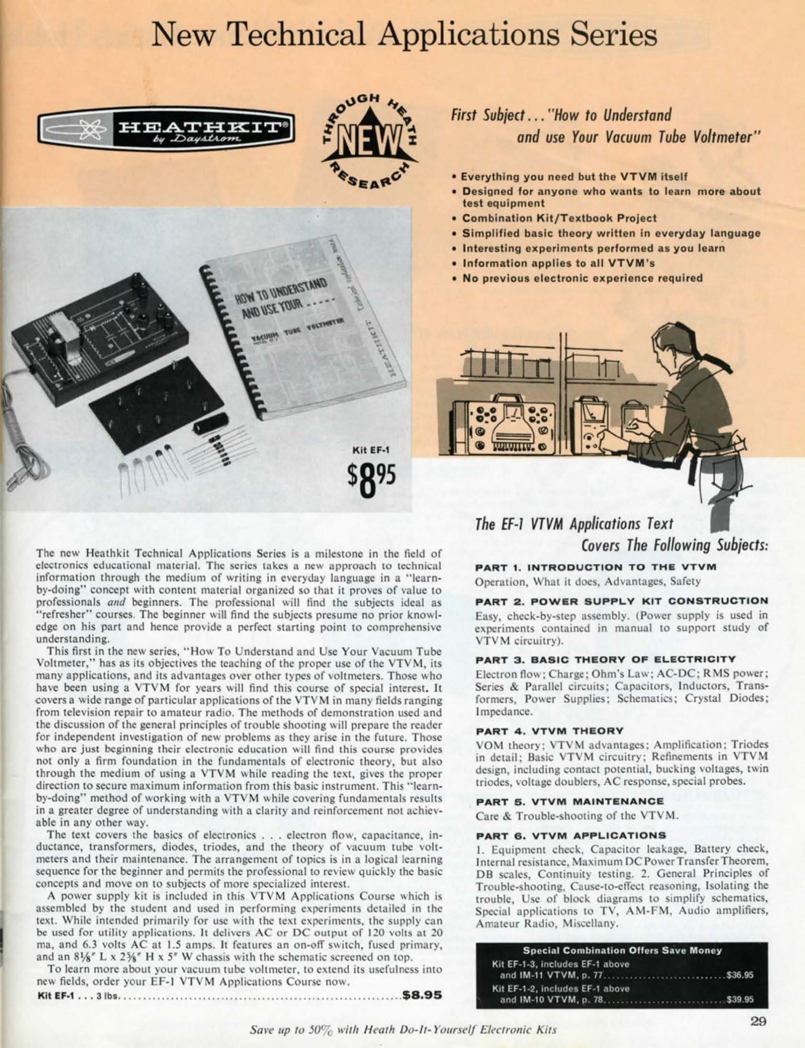
From 1961 Heath sold a course to go with the instrument. EF-1, “How To Understand and Use Your Vacuum Tube Voltmeter”, was the first of the Heathkit Technical Application Series: a textbook plus a small power-supply kit and a set of experiments, sold at $9.95 on its own or bundled with a meter. Its syllabus started with electron flow, charge and Ohm’s law and worked through VOM theory and triodes to circuit measurements in radio and television servicing — a reminder that Heath’s customer for this instrument was very often someone who had bought it in order to learn.
4.7 Keeping it honest
A VTVM in regular use wants its zero checked at the start of a session and its calibration checked occasionally against something known. Three cheap checks cover most of it: a fresh cell against the red dot for DC, a handful of 1 per cent resistors for the ohms ranges, and a trusted digital meter on the same mains outlet for AC. Any drift that appears between DC+ and DC− points at the 12AU7 rather than the calibration.
The bench models make this easier than the table-tops. From the IM-13 onward the three internal controls — DC CALIBRATE, AC CALIBRATE and AC BALANCE — are reachable through holes in the front panel, so a calibration check does not mean removing the cabinet (Eckweiler #110).
Sources
- Heathkit Assembly Manual, Vacuum Tube Voltmeter Model IM-11 (595-486). https://archive.org/details/heathkitassembly00unse_7
- Heathkit Assembly Manual, Vacuum Tube Voltmeter Model V-7A (595-110). https://archive.org/details/heathkitmanualva00unse
- Heathkit Assembly Manual, Vacuum Tube Voltmeter Model IM-18 (595-1154). https://archive.org/details/heathkitassembly00unse_4
- Eckweiler, Bob (AF6C). “Heathkit of the Month #19: V-7A VTVM.” https://www.w6ze.org/Heathkit/Heathkit_019_V7a.pdf
- Eckweiler, Bob (AF6C). “Heath of the Month #110: Heathkit ‘Deluxe Service Bench’ VTVMs.” https://www.w6ze.org/Heathkit/Heathkit_110_DSB_VTVMs.pdf
- Eckweiler, Bob (AF6C). “Heath of the Month #118 and #119: Heathkit Probes, parts I and II.” https://www.w6ze.org/Heathkit/Heathkit_118_Probes_I.pdf · https://www.w6ze.org/Heathkit/Heathkit_119_Probes_II.pdf
- Heyning, Bjorn. Heath Stories. https://www.heco.wxwilki.com/wwheco2/hs_vol1.txt
- Post, Rich (KB8TAD). “The Heathkit Legacy.” http://boatanchorpix.x10host.com/HLegacy.htm
- Heath Company catalogues, World Radio History. https://www.worldradiohistory.com/Archive-Catalogs/Heathkit_Catalogs.htm
Comments (0)