ET-3100 Analog Trainer · Volume 2
How It Works
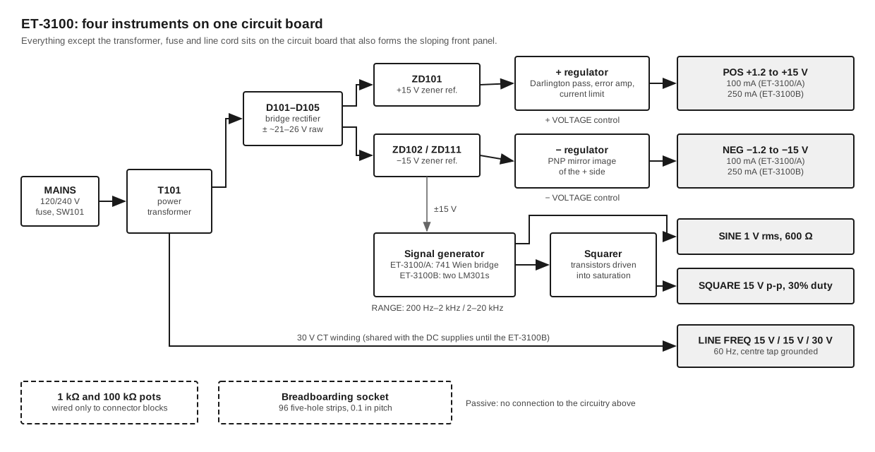
Inside the ET-3100 are four independent circuits sharing one transformer and one printed circuit board: a positive and a negative regulated supply, an audio oscillator with a squaring stage, and a pair of transformer taps. Two potentiometers and the breadboarding socket are wired to nothing but their own connector blocks. None of it is difficult. That was intended, because a student who reached the fourth Heath course, EE-3104 Electronic Circuits, met the trainer’s own power supply as the final worked example in the chapter on regulators (the courses volume covers this). This volume walks through the circuits of the original ET-3100 and then the changes made in the A and B versions.
2.1 The board is the panel
The first thing a builder notices about the ET-3100 is that it has no chassis. The single circuit board (85-2730 in the B; the original’s number is not legible in the available scan) is printed on its component side with the panel legends (“POWER SUPPLY”, “LINE FREQ”, “GENERATOR”, the dial markings for every knob), and it is screwed face-up under the cabinet top so that it is the sloping front panel. The controls, slide switch, rocker switch, connector blocks and breadboarding socket all mount directly on it. The small components sit in a strip along the top edge, hidden under the overhang that carries the nameplate. The manual’s “Circuit Board X-Ray View” shows this plainly: component outlines and panel artwork on the same drawing (ET-3100B manual, Illustration Booklet p. 12). Eckweiler notes that the board and the transformer shell are the only “chassis” parts, bonded together and to the mains earth on the three-wire versions (HotM #129).
Only the transformer, the fuse and the line cord live elsewhere, in the cabinet bottom. The mains wiring is enclosed in a small box moulded into the bottom and closed with a screwed insulator plate. That arrangement mattered for a product that students would open, and the A revision improved it further.
2.2 Power: one transformer, one bridge, two rails
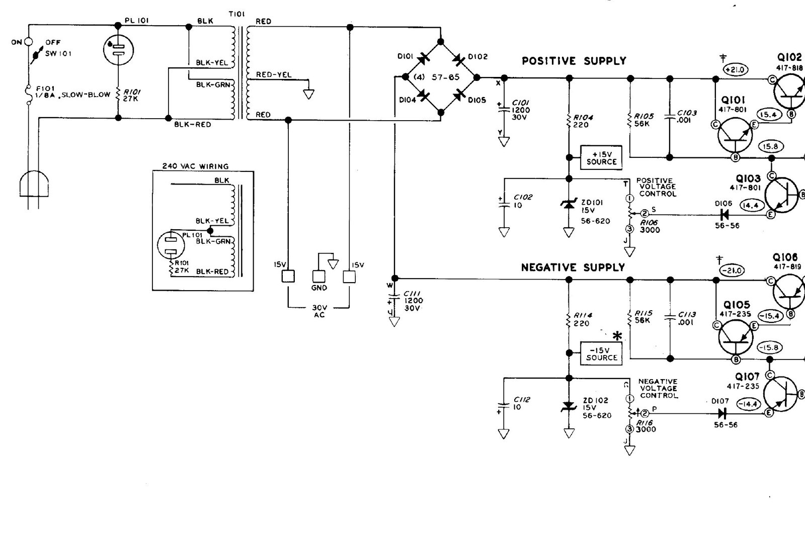
The original ET-3100 has a single transformer, T101 (Heath 54-892), with a dual primary for 120 or 240 V and one centre-tapped secondary rated at 30 V CT, 200 mA (HotM #129). The centre tap is grounded. A four-diode bridge of 1N4002s (D101, D102, D104, D105) across the full winding charges two reservoir capacitors, C101 to about +21 V and C111 to about −21 V. The schematic marks them 1200 µF, 30 V, while the parts list calls for 1000 µF electrolytics (25-876); either is plausible and the schematic figure may reflect an earlier parts choice.
The same two ends of the winding and its centre tap go straight to the LINE FREQ connector blocks: 15 V from block 1 to block 2, 15 V from block 2 to block 3, and 30 V across 1 and 3, with block 2 at ground. The two jobs share one 200 mA winding, which explains a line in the manual’s specifications that is easy to skip: the 60 Hz outputs deliver “200 mA maximum (total current from all supplies must not exceed 200 mA)” (ET-3100 manual, p. 28).
The EE-3104 text uses this arrangement to teach the dual-polarity bridge. “In the secondary, a single bridge rectifier is used to produce both negative and positive supply voltages,” it says, and on alternate half-cycles one pair of diodes charges the positive capacitor while the other pair charges the negative one, with the return for both through the grounded centre tap (EE-3104-B Electronic Circuits, Unit 4, “ET-3100 Power Supply”).
2.3 The regulated supplies
Each supply is a discrete series regulator of a kind that fills textbooks of the period. The positive side is described here; the negative side is its mirror image with PNP transistors and reversed diodes.
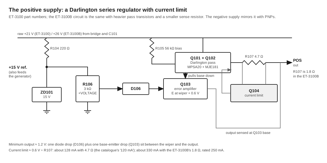
Reference. A 15 V zener, ZD101, fed from the raw +21 V through R104 (220 Ω) and bypassed by C102, gives a stiff +15 V. This node does two jobs. It is the reference for the adjustable supply, and it also powers the signal generator; the schematic marks every point that draws from it with a star, “NOT THE VARIABLE DC OUTPUT.” Because the generator runs from the zener reference rather than from the adjustable output, it keeps full swing whatever the VOLTAGE knobs are doing.
Setting the voltage. The front-panel + VOLTAGE control, R106 (3 kΩ, linear), sits across the reference, so its wiper can be anywhere from 0 to +15 V.
Pass element. Q101 (MPSA20) and Q102 (MJE181, a TO-126 power transistor bolted to a small heat sink) are connected as a Darlington, collectors to the raw supply, with R105 (56 kΩ) biasing them on. Left alone they would pull the output up toward the raw voltage.
Error amplifier. Q103 (MPSA20) has its base on the output and its emitter at the wiper voltage plus one diode drop through D106. When the output rises more than a base-emitter drop above the emitter, Q103 conducts and steals base current from the Darlington, and the output settles. The EE-3104 text explains the consequence that gives the supply its odd lower limit: “because of the 0.6 volt drop across D106 and the 0.6 volt VBE drop in Q103, the output voltage cannot fall below about 1.2 volts” (EE-3104-B). The 1.2 V on every specification sheet comes from those two junctions.
Current limit. The output leaves through R107, 4.7 Ω. Q104 has its base-emitter junction across that resistor. At about 0.6 V across it, which is about 128 mA, Q104 turns on, pulls down the Darlington’s base and holds the current there. The EE-3104 text puts the limit at “about 120 mA”, which is where the catalogue’s “120 mA” came from. The manual rated the supply at 100 mA, leaving a margin below the fold. Both numbers describe the same circuit, and Heath’s advertising printed one while its manual printed the other for six years.
The catalogue’s “1.2 to 16 volts” has a similar explanation. With the knob fully clockwise the wiper sits at the zener voltage, and a 15 V zener at 5% tolerance plus 1.2 V of junction drops can reach a little above 16 V. The manual, written for all units, promised 15.
The same regulator looks unremarkable today. In 1975 it was a sensible choice for a kit. Adjustable three-terminal regulator ICs were only then reaching the market, and the discrete circuit could be serviced with an ohmmeter and a handful of general-purpose transistors. It also had the advantage, for a teaching company, of being explainable one transistor at a time.
2.4 The generator: a Wien bridge with a light bulb
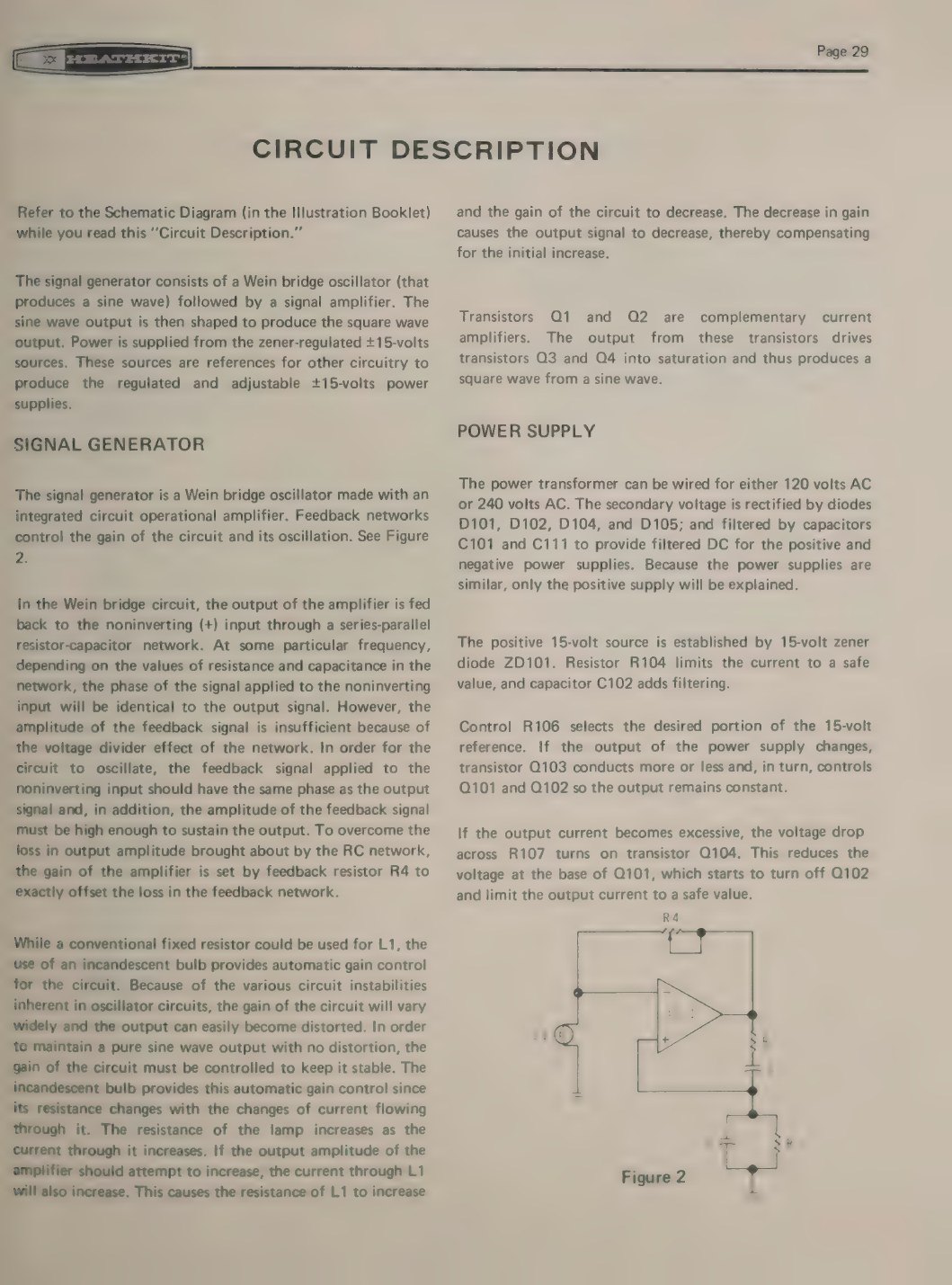
The original ET-3100’s oscillator is the circuit that made Hewlett-Packard’s name in 1939: a Wien-bridge oscillator whose amplitude is held steady by the resistance of a small incandescent lamp (HP 200A, Wikipedia). Heath built it around a single 741 op-amp, IC1, and the manual’s circuit description is a clear account of how it works.
A series RC arm (R3 + R5 with C3 or C4) runs from the op-amp’s output to its non-inverting input, and a parallel RC arm (R1 + R2 with C1 or C2) runs from that input to ground. At one frequency the two arms give zero phase shift and pass about a third of the output back to the input; at every other frequency they shift the phase and the loop cannot sustain itself. The amplifier’s gain, set by negative feedback between R4 and the lamp L1, has to make up exactly that loss. Too little gain and the oscillation dies; too much and it grows until the op-amp clips. The manual explains the lamp: “While a conventional fixed resistor could be used for L1, the use of an incandescent bulb provides automatic gain control for the circuit … The resistance of the lamp increases as the current through it increases. If the output amplitude of the amplifier should attempt to increase, the current through L1 will also increase. This causes the resistance of L1 to increase and the gain of the circuit to decrease” (ET-3100 manual, p. 29).
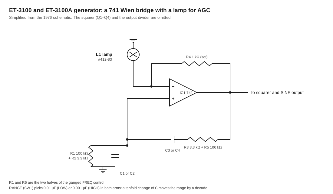
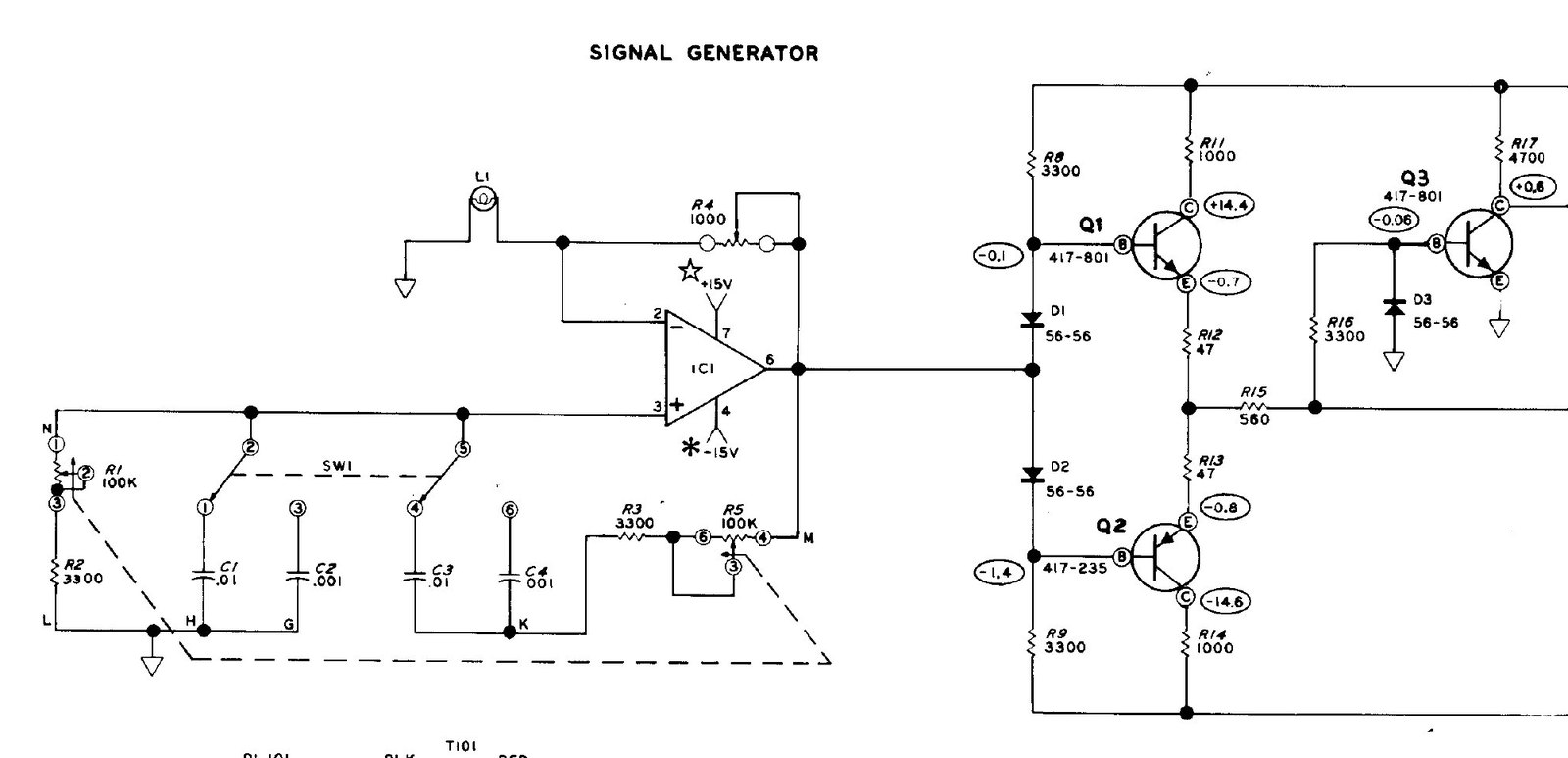
The two capacitor values differ by a factor of ten, so RANGE moves the oscillator up or down by a decade. The ganged 100 kΩ control, R1/R5, tunes within the range. Both arms have to change together to keep the bridge balanced, which is why the FREQ control is a dual potentiometer. Fixed 3.3 kΩ resistors (R2, R3) in series with each half stop the frequency running away at the end of the rotation.
The only adjustment in the kit is the gain trimmer R4, and it is set during test with nothing but the eye. The manual says: “Lamp L1 should be dimly lit. Adjust the Feedback control, R4, clockwise until the filament of the lamp just stops glowing. Then turn it back counterclockwise until the lamp is again dimly lit.” With an oscilloscope the builder was to set R4 “for a maximum undistorted signal” instead (ET-3100 manual, p. 21). The two instructions find the same point, the edge of oscillation where the lamp is working in its useful range. The weakness of the circuit is also visible here. A lamp’s resistance depends on its temperature, and a small filament takes time to heat, so the amplitude settles slowly after the frequency or range is changed and can bounce before it settles. The ET-3100B’s circuit description later made a point of fixing exactly that.
2.4.1 Sine to square
The op-amp’s output drives a complementary pair, Q1 (MPSA20, NPN) and Q2 (2N4121, PNP), biased just into conduction by the diodes D1 and D2. This is the arrangement the manual calls “complementary current amplifiers.” The pair’s output drives Q3, an MPSA20 with a diode clamp (D3) on its base, which switches hard between cut-off and saturation. Q4 inverts again, with a 2.2 kΩ collector load to the +15 V reference, and its collector is the SQUARE output. That explains the square-wave specification: 15 V peak-to-peak, from “+15 volts maximum” down to about 0.1 V (the saturation voltage of Q4), with a rise time under a microsecond and a duty cycle of about 30% rather than 50%. The squarer switches at a threshold that is not at the centre of the sine wave, so the high part of each cycle is the shorter one.
The sine output is brought to its own connector block and specified as 1 V rms from 600 Ω, the traditional audio-line impedance.
2.5 The A: same circuit, safer mains
The ET-3100A changed no part of the circuit described so far. Its revision was confined to the mains side and the pilot lamp (HotM #129):
- a three-wire line cord in place of the two-wire cord, with the board and transformer bonded to earth;
- a panel-mounted fuse holder in the side of the cabinet in place of fuse clips inside the moulded box;
- an insulator over the power-switch lugs;
- an LED pilot lamp fed from the +15 V zener through a 1 kΩ resistor (R101 had been 27 kΩ for the neon lamp across the primary); and, because the LED now drew current from the reference, R104 reduced from 220 Ω ½ W to 150 Ω 1 W.
The generator, the supplies and the specifications were unchanged; Eckweiler’s Table I gives identical figures for the ET-3100 and ET-3100A.
2.6 The B: more current, a new oscillator
The ET-3100B of 1982 kept the panel and the functions but changed a good deal behind them.
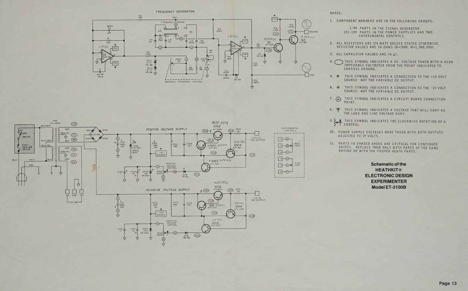
Power. A new transformer, 54-1005, has two secondaries. One is the familiar 30 V CT winding, now used only for the LINE FREQ outputs. The other feeds the bridge and gives about +26 V and −26 V raw. Heath’s master parts file calls it “20 VCT at 600 mA”, which Eckweiler argues must mean 20-0-20 V at 300 mA to give the voltages the schematic shows (HotM #129, note 5). The regulators keep the same topology with new parts: MJE5979 and MJE5976 pass transistors on heat sinks (Q102, Q112), 1N4744A zeners, and a current-sense resistor cut from 4.7 Ω to 1.8 Ω. At 0.6 V that trips at about 330 mA, and the rating rose to 250 mA per supply; load regulation was relaxed from 1% to 2% to match. Power consumption rose from 7 W to 25 W. The zener feed resistors (R102, R112) are 330 Ω 1 W in the B’s parts list; Eckweiler gives 220 Ω, and the manual is followed here. The LED pilot moved to the raw +26 V through 1.8 kΩ (ET-3100B manual, pp. 7, 35).
Generator. The Wien bridge and its lamp are gone. The ET-3100B manual describes the replacement: “The frequency generator consists of a pair of LM-301 operational amplifiers. IC U2 is the tuned oscillator, while IC U1 provides signal amplification and phase reversal for IC U2 to continue oscillation.” Two 2.7 V zeners, ZD1 and ZD2, limit the level fed into the frequency-determining network, and the dual FREQ control is now asymmetric (200 kΩ/5 kΩ): R9 tunes, and R5, turning with it, raises the drive level as the frequency rises so the amplitude stays roughly constant. The capacitors became 0.02 µF for LOW and 0.0022 µF for HIGH. The manual states the benefit plainly: “Since the circuit does not require an AGC loop, the oscillator starts quickly and reaches final amplitude within a few cycles” (ET-3100B manual, p. 35).
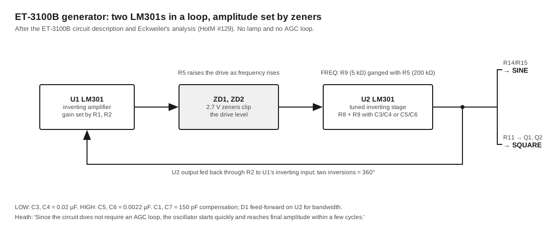
The squarer was simplified to two MPSA20s, Q1 and Q2, driven from the sine output through R11 with D2 clamping Q1’s base. The specifications for the sine and square outputs did not change. The circuit description admits one thing the catalogue did not: the ranges are now “nominal,” and the test procedure allows ±20% on the end frequencies.
2.7 The passive parts
The two “experimental controls” are a 1 kΩ (R122) and a 100 kΩ (R121) linear potentiometer, each with its three terminals brought to three connector blocks labelled 1, 2 and 3 (counter-clockwise end, wiper, clockwise end). They are not connected to anything else, and the courses used them as variable resistors, voltage dividers and volume controls.
The fifteen connector blocks are four-hole spring sockets, all four holes in a block common, which accept solid wire up to #20 (0.032 inch). The breadboarding socket in the centre is the same idea on a larger scale: 96 vertical strips of five holes, 48 above and 48 below a central channel 0.3 inch wide, on 0.1-inch centres, so that a dual-in-line IC straddles the channel with each pin on its own strip (HotM #129; the 1975 catalogue called it “96 terminals with 5 common connections each, arranged as 48 pairs”). Unusually for later breadboards, it has no built-in power buses; students ran wires from the POS, GND and NEG blocks to whichever strips they wanted to use as rails. The kit supplied an IC puller that fits the centre channel.
2.8 What the student could see
Heath printed DC voltages at every transistor terminal on both schematics, measured “with a high impedance voltmeter” with both supplies set to 15 V, and the original manual added a separate Voltage Chart drawn over the board layout. With a VTVM a builder could compare readings against those figures, and a course student could use the trainer as its own troubleshooting exercise. The restoration volume uses them for that purpose.
Sources
- Heath Company, ET-3100 assembly manual, 595-1734-06 (circuit description p. 29, specifications p. 28, test p. 21): https://archive.org/details/manualsplus_11837
- Heath Company, ET-3100 schematic, part of 595-1734-02, © 1976: https://archive.org/details/heathkit_et-3100 (also https://archive.org/details/HeathkitET3100ElectronicDesignExperimenterschematic_201502)
- Heath Company, ET-3100B assembly manual, 595-2860-03 (circuit description p. 35, parts list pp. 7–8, schematic Illustration Booklet p. 13): https://archive.org/details/heathkitmanualfo00unse_0
- Heathkit Educational Systems, Electronic Circuits, EE-3104-B, third edition, 1998, Unit 4, “ET-3100 Power Supply” and Figure 4-62: https://archive.org/details/ee-3104-b-electronic-circuits-individual-learning-system-textbook-1998
- Bob Eckweiler, AF6C, Heathkit of the Month #129 (ET-3100/A/B), rev. 1, 2026: https://www.w6ze.org/Heathkit/Heathkit_129_ET3100B.pdf; schematics and parts lists for all three versions: https://www.w6ze.org/Heathkit/ET-3100/index.html
- “HP 200A”, Wikipedia, for the lamp-stabilised Wien-bridge oscillator: https://en.wikipedia.org/wiki/HP_200A
Comments (0)