ET-3100 Analog Trainer · Volume 3
Building the Kit
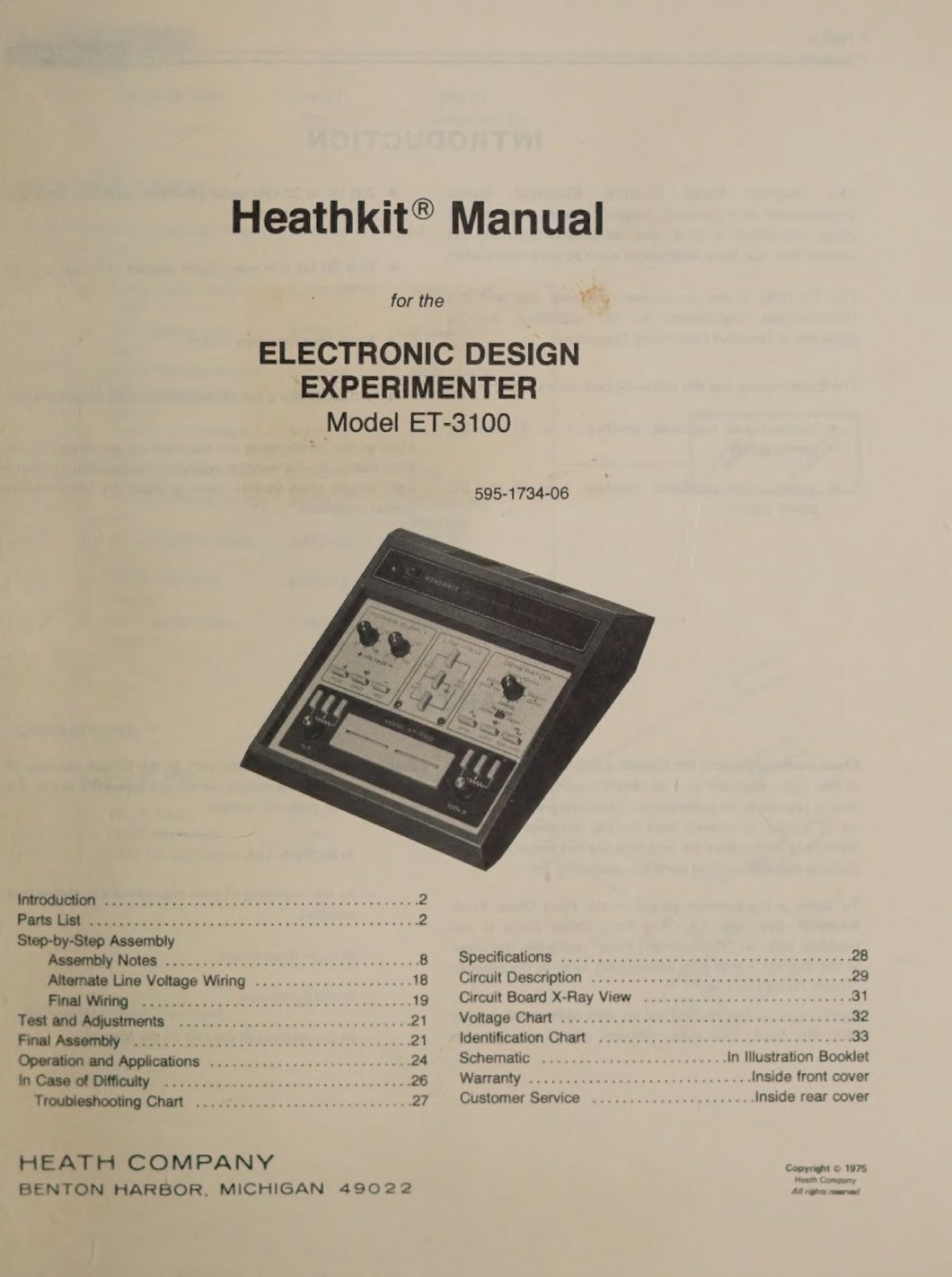
The ET-3100 was a small kit and was meant to be. Most of its parts go onto one printed circuit board, the only mains wiring is a handful of joints in a moulded box, and there is no alignment beyond one trimmer (none at all on the B). For a course student it was usually the first thing built, before the first binder was opened, and it doubled as a soldering lesson. This volume follows the two manuals that survive in full: the original ET-3100 manual, 595-1734-06, and the ET-3100B manual, 595-2860-03.
3.1 What was in the box
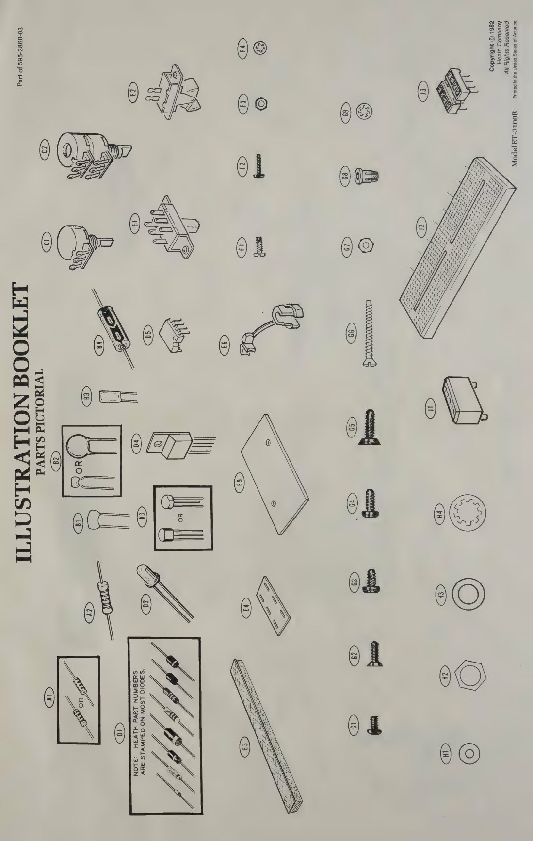
The original parts list runs to about a hundred items once hardware is counted. For the circuit there are about twenty quarter-watt resistors; ten capacitors, of which the two big electrolytics are the only bulky parts; six controls (the five panel controls and the feedback trimmer R4); five 1N4149 signal diodes, two 15 V zeners and four 1N4002 rectifiers; twelve transistors (six MPSA20, four 2N4121, and the MJE181 and MJE171 pass transistors); and one 741 op-amp with its eight-pin socket. The panel parts are a DPDT slide switch, an SPST rocker switch, fifteen connector blocks and the breadboarding socket, which comes as a moulded block into which the builder presses the contact strips. Then there are two lamps, the neon pilot (412-15) and the small incandescent lamp that stabilises the oscillator (412-83), a 1/8 A slow-blow fuse with its clips, the transformer (54-892), a line cord, a cabinet top and bottom, five knobs, feet and labels (ET-3100 manual, pp. 3–7).
The B’s list is similar but reflects its changes: two LM301s in place of the 741, two heat sinks and a tube of silicone grease for the new pass transistors, an LED in place of both lamps, a fuse holder, a three-wire line cord with strain relief, the larger transformer (54-1005), foam tape for mounting the filter capacitors, an FCC label and a nut starter (ET-3100B manual, pp. 7–8). Both kits included an IC puller, a reminder that the trainer was expected to see a great many ICs pushed into and pulled out of its socket.
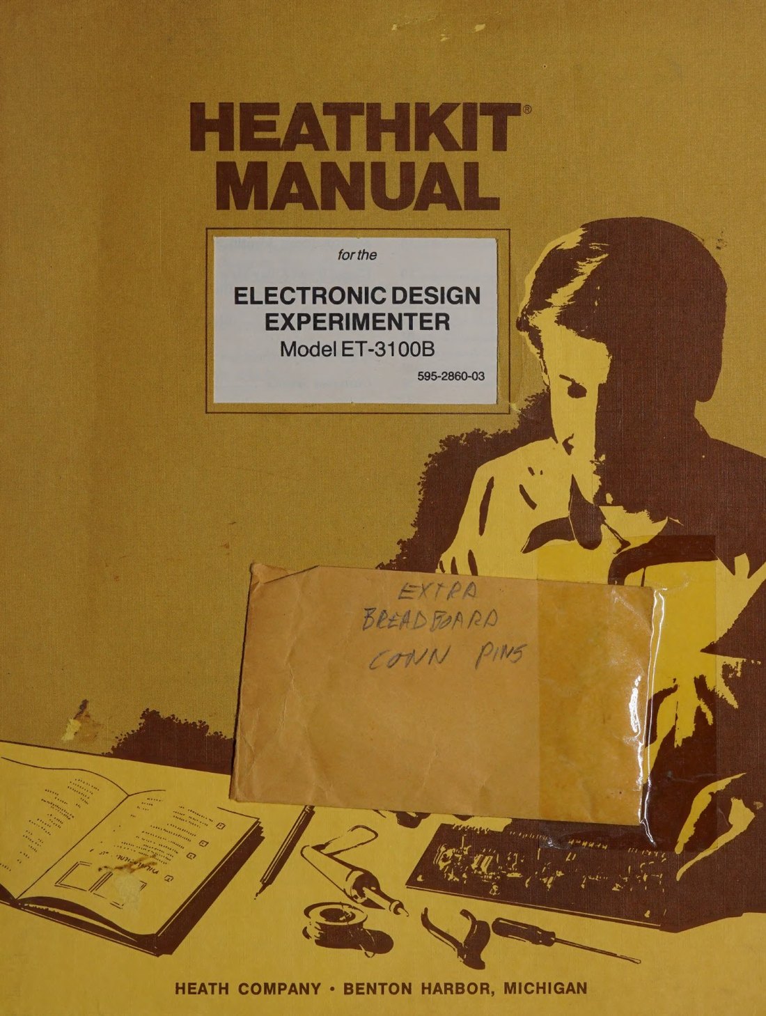
A trainer bought as part of a course package arrived with the course parts too, and those could confuse a builder. Bob Eckweiler, examining a boxed ET-3100 for his 2025 article, found two envelopes of resistors among the kit parts that turned out to belong to the DC Electronics course. One was marked “RESISTORS FOR EXPERIMENT 5” and held a 100 MΩ and a 1,000 MΩ carbon resistor, values chosen for a colour-code exercise rather than for any circuit (HotM #129).
3.2 How the manual is organised
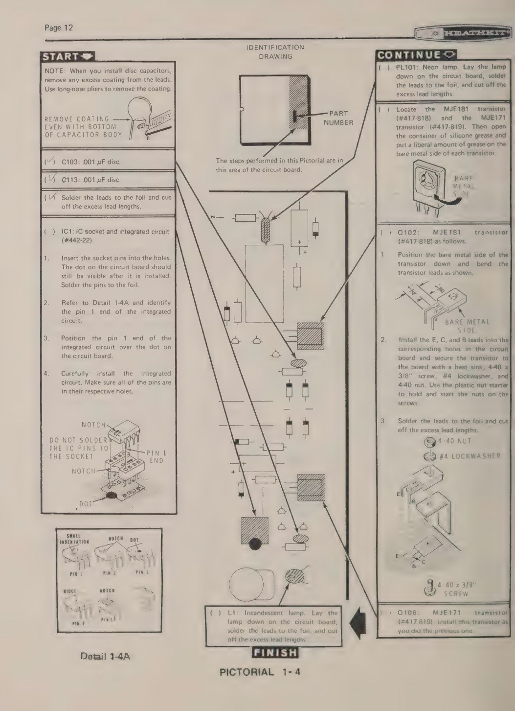
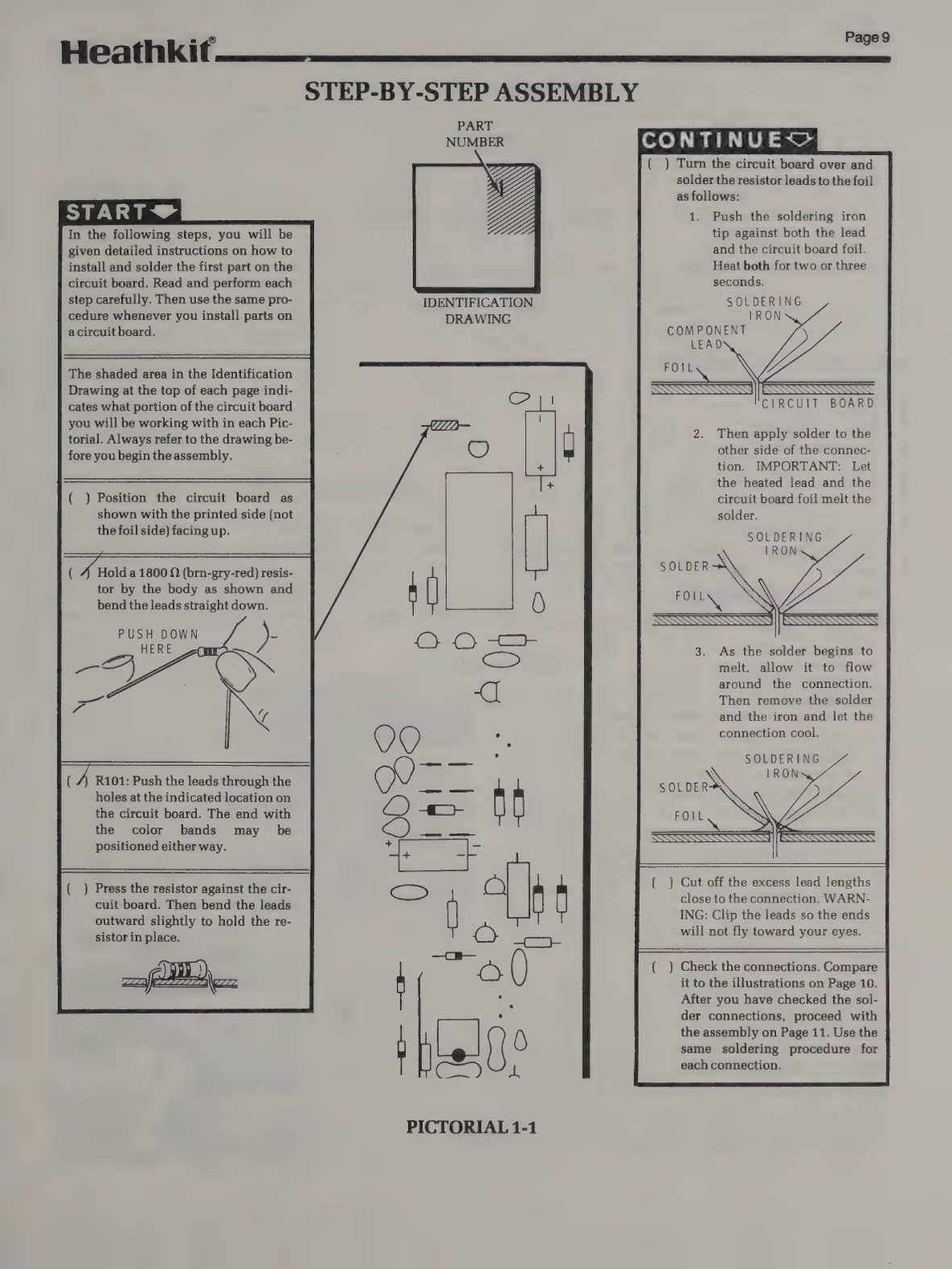
Both manuals are standard Heath manuals of their period: an assembly manual with a check-box beside every step, and a separate Illustration Booklet for the drawings too large for the page. The B manual states the convention: “The illustrations in the Manual are called Pictorials and Details. Pictorials show the overall operation for a group of assembly steps; Details generally illustrate a single step.” Each board-stuffing page has a START box at the top left, a column of steps that continues into a CONTINUE box, and a FINISH marker, with an identification drawing that shades the part of the board being worked on. Arrows run from each step to the place the part goes. Rulers printed along the page margins let the builder measure wire lengths without a ruler of their own.
3.3 The order of work
The two manuals build the kit in the same order.
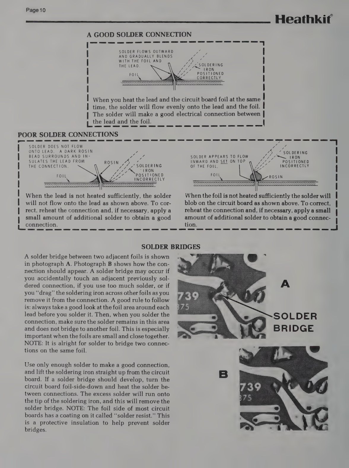
1. Small parts on the board. Resistors, diodes, zeners, capacitors, the IC socket and the transistors go in first, in groups of five to ten per pictorial (Pictorials 1-1 to 1-4 in the original, 1-1 to 1-6 in the B). The B’s manual gives the first resistor as a worked example and then inserts a two-page lesson on soldering, “A Good Solder Connection”, with photographs of a solder bridge before and after. The pass transistors are the only parts needing mechanical work: the metal side of each TO-126 package is greased and bolted to a small heat sink on the board with a 4-40 screw. On the original, the neon pilot and the oscillator lamp are soldered in lying flat against the board.
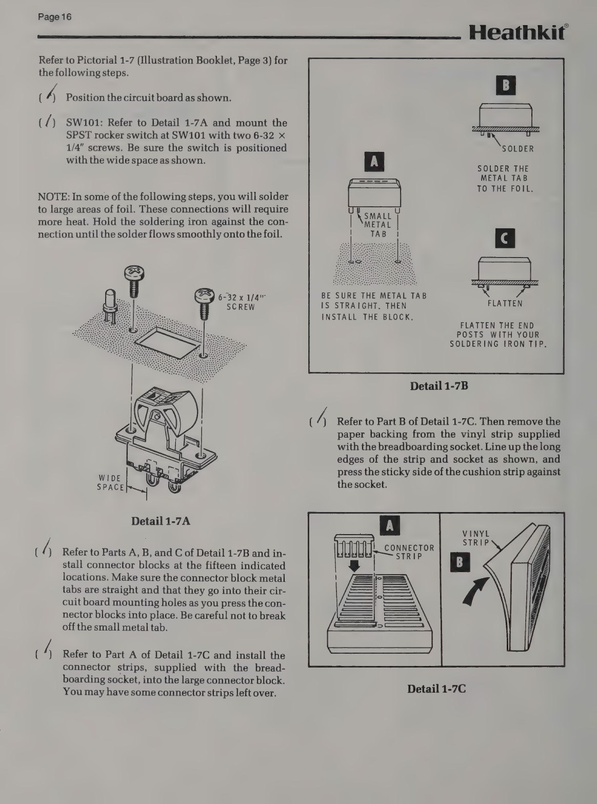
2. The panel hardware. Next comes the part of the build that makes the board a front panel. The rocker switch is screwed down. The fifteen connector blocks are pressed into the board by their metal tabs and soldered, and their end posts are flattened with the soldering iron to lock them. Then the builder assembles the breadboarding socket. The contact strips supplied with it are pushed one at a time into the large moulded block (“You may have some connector strips left over”), a sticky vinyl cushion strip is pressed onto its underside, the screwdriver tip is used to punch through the vinyl at the three mounting holes, and the finished socket is screwed to the board. The five potentiometers go in with the usual nut, flat washer and lockwasher, and the RANGE slide switch is soldered on by its tabs from the foil side.
3. Foil-side wiring. The board is turned over and the controls are wired to the foil with short lengths of solid wire. Heath’s “(NS)” (do not solder yet) and “(S-2)” (solder, two wires in this joint) notation keeps track of shared joints. The range capacitors are wired between the slide-switch lugs and the foil with sleeving over one lead. On the B, the two big filter capacitors are mounted on this side too, stuck down on foam tape over the etched letters, and the manual reassures the builder that “the letters are screened on the other (component) side of the circuit board for reference.” The two red stranded leads from the power switch get heat-shrink sleeving over the switch lugs. The step ends with a “Circuit Board Checkout” for solder bridges, protruding leads, transistor types, capacitor polarity and diode bands.
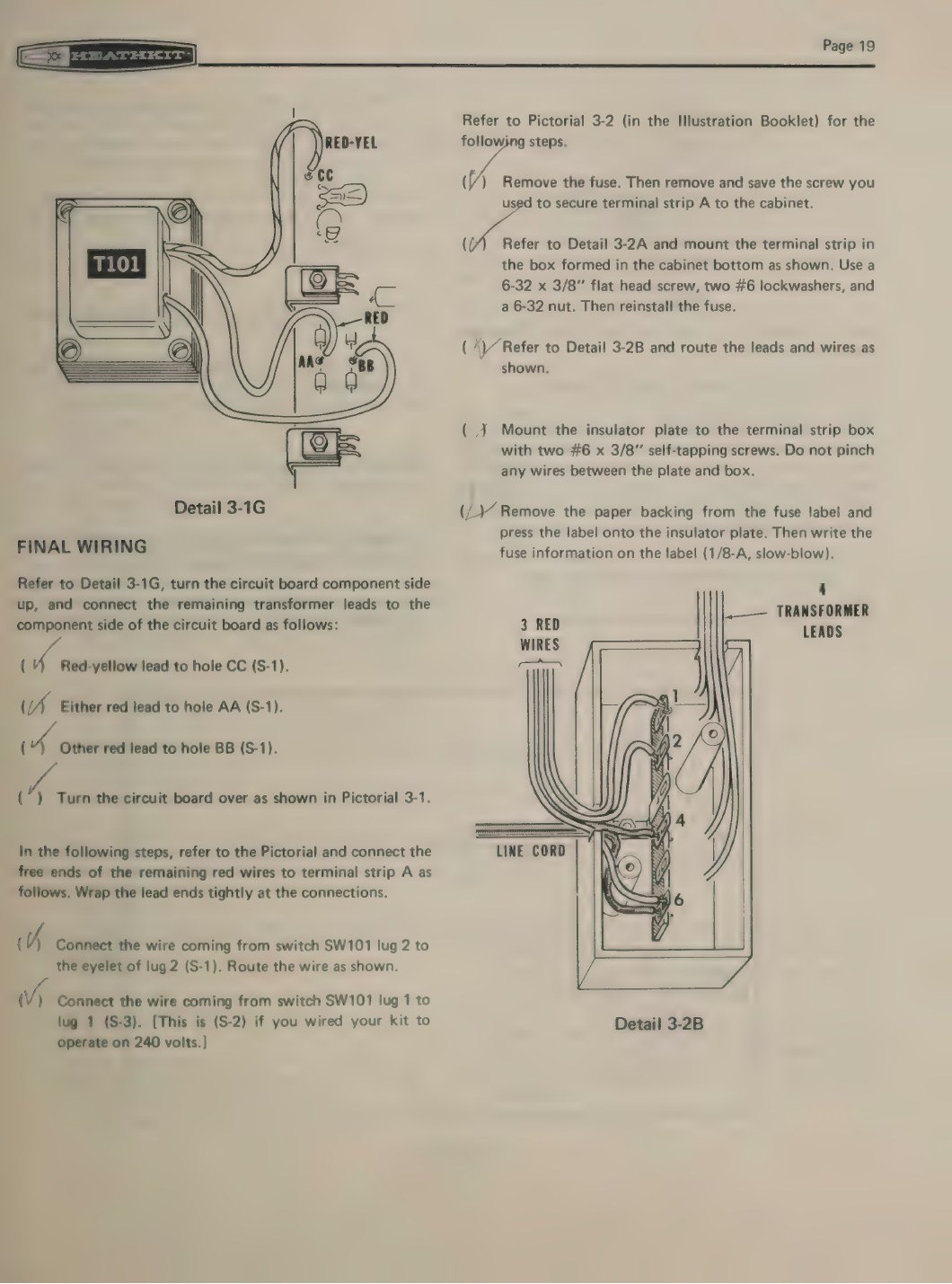
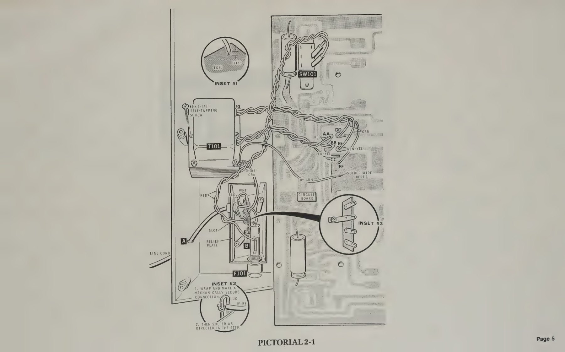
4. The cabinet and mains wiring. The mains parts go into the moulded box in the cabinet bottom. The two versions differ most here. The original ET-3100 used a two-wire cord, passed through a hole and knotted inside as its strain relief (“tie a knot in the line cord 4-1/4” from the end”), with the smooth and ribbed leads identified for the terminal strip, and a 1/8 A slow-blow fuse soldered into clips on a six-lug terminal strip (ET-3100 manual, pp. 18–19). The B uses a three-wire cord with a moulded strain relief and a relief plate, a panel fuse holder in the cabinet side, and a four-lug terminal strip, and runs a green ground wire from a solder lug under a transformer screw to the terminal strip and on to the board’s common foil (ET-3100B manual, pp. 23–25). Both manuals give “Alternate Line Voltage Wiring” instructions for 120 V and 240 V, and both warn: “USE ONLY THE INSTRUCTIONS THAT AGREE WITH THE LINE VOLTAGE IN YOUR AREA.” An insulator plate is then screwed over the box.
5. Final wiring. The transformer’s secondary leads, twisted in threes, are soldered to lettered holes in the board (AA, BB, CC; on the B also DD, EE, FF for the second winding). The knobs follow. On the B they are two-part, a tapered bushing pressed into each knob with a nutdriver after the pointer has been lined up with the control turned fully counter-clockwise, and the manual spends a full detail drawing on how not to mar the knob.
3.4 Testing it
Neither manual asks for any test equipment beyond what a course student might own, and both allow the builder to skip steps for which no instrument is available.
The original ET-3100 is tested with the board lying in the cabinet bottom and a piece of cardboard under the power switch, with a warning not to touch the area marked “high-voltage area”. When the cord is plugged in, the neon lamp should light (if not, “push switch SW101 to the other position”; the rocker had no fixed “on” side until it was installed). The oscillator lamp L1 should be dimly lit, and the builder sets R4 by eye, turning it until the filament just goes out and then back until it glows again. Anyone with an oscilloscope was told to watch the SINE block instead and set R4 “for a maximum undistorted signal”. With a voltmeter, each supply is swept from 1 to 15 V (ET-3100 manual, p. 21).
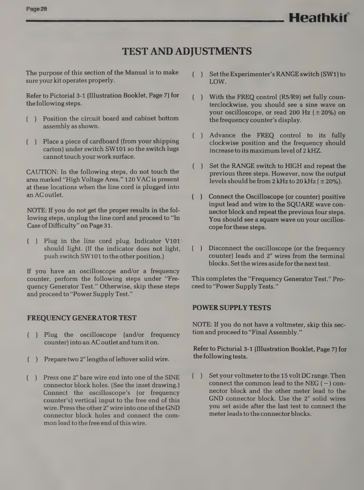
The ET-3100B has no adjustment at all. Its “Test and Adjustments” section checks the generator’s end frequencies with an oscilloscope or counter (200 Hz and 2 kHz on LOW, 2 kHz and 20 kHz on HIGH, each ±20%), sweeps both supplies with a voltmeter, and then measures 15, 15 and 30 V AC across the LINE FREQ blocks (ET-3100B manual, pp. 28–29). Short pieces of leftover solid wire, pushed into the connector blocks, serve as test points.
Final assembly is the same in both: the board is screwed face-up under the cabinet top (eight self-tapping screws on the original, seven plus a cable clamp on the B; two of the screw heads are visible in the LINE FREQ panel), the halves are screwed together, labels and feet are applied, and “You can use the remaining wire for your experiments.” Both manuals then go straight to “Operation and Applications”, which is the courses volume’s subject.
3.5 Tools and time
The ET-3100B manual lists the tools: long-nose pliers, diagonal cutters, wire strippers, 1/8- and 1/4-inch blade screwdrivers, a Phillips screwdriver and a 22–25 W pencil soldering iron, with a desoldering bulb and a nut starter as “other helpful tools” (the nut starter was supplied). Heath insisted on rosin-core 60/40 solder and warned that acid-core solder voided the warranty. Nothing else is needed. There is no chassis to punch, no cable to lace and no alignment instrument to borrow.
No build-time figure from Heath has been found. The assembly sections run to sixteen pages in the original manual and about twenty in the B, of which Eckweiler counts twelve and a quarter pages for the board. By the standard of Heath’s test-equipment kits, that places the ET-3100 among the shortest builds of its period; a careful first-time builder working through the soldering lessons would likely finish in an evening or two, but that estimate is not Heath’s.
3.6 When it went wrong
Both manuals carry the standard Heath advice that “about 90% of the kits that are returned to the Heath Company for repair do not function properly due to poor connections and soldering,” a short troubleshooting chart and, in the original, a full-page voltage chart drawn over the board layout. The chart shows how little can go wrong with the circuit: no output from either supply points to the fuse, the transformer or the bridge; a supply that stays high or will not come up points to its three regulator transistors; and a dead or distorted generator points, on the original, to “Control R4 misadjusted”, the 741, or the wiring of the dual FREQ control (ET-3100 manual, p. 27). Those are also the faults that appear decades later, and the restoration volume returns to them.
3.7 What builders said
Contemporary reviews of the ET-3100 have not been found; Heath’s education products were rarely sent to the magazines that reviewed its test equipment. Later accounts are few but consistent. Eckweiler’s first impression, examining a complete ET-3100B and its manuals in 2025, was “very positive”, with one reservation: “the breadboard could have been larger. All the experiments easily fit on it. Yet, I wondered about using it later on, on other projects?” (HotM #129). The owner of a Swedish OEM unit made the same point in practice by extending the breadboard and adding 4 mm test terminals so that a meter or oscilloscope could be clipped on (heathkit.nu). A radio amateur who restored one found the supplies “poorly filtered and regulated” by modern standards but acceptable for experiments, and still recommended the trainer at a reasonable price (W0MPM).
Sources
- Heath Company, ET-3100 assembly manual, 595-1734-06, © 1975 (parts list pp. 3–7; assembly pp. 8–23; test p. 21; troubleshooting p. 27): https://archive.org/details/manualsplus_11837
- Heath Company, ET-3100B assembly manual, 595-2860-03, © 1982 (tools p. 4; parts list pp. 7–8; assembly pp. 9–27; test pp. 28–29): https://archive.org/details/heathkitmanualfo00unse_0
- Bob Eckweiler, AF6C, Heathkit of the Month #129, rev. 1, 2026: https://www.w6ze.org/Heathkit/Heathkit_129_ET3100B.pdf
- heathkit.nu, ET-3100 page: http://heathkit.nu/heathkit_nu_ET-3100.html
- W0MPM, “Heathkit ET-3100 Experimenter and Breadboard”: https://qsl.net/w0mpm/HeathkitET3100.html
Comments (0)