GR-2000 Color Television · Volume 4
Setting Up and Converging
The moment that separates a colour television kit from every other kit is the first switch-on. A receiver that works produces a picture that is nevertheless wrong: the colours sit in the wrong places, the three beams do not land on their own phosphor dots, and the three images do not lie on top of one another. Making them do so is a craft procedure, normally a service call, and Heath’s whole television programme was built on the proposition that an owner could do it himself with instruments built into the set. This volume describes how, from the resistance checks made before the chassis is plugged in to the dynamic convergence that finishes the job, and then how the set was used.
One caveat on sources runs through it. No scan of the GR-2000’s own Book Three has been found. The procedures below are taken from the surviving Book Three for the GR-2001, the successor that used the same chassis architecture, the same self-service facilities and much of the same text (595-1865-06, 1976), and are cross-checked against what Heath and the magazines wrote about the GR-2000 itself. Where the two sets differ — chiefly in tuning, since the GR-2001 has a keyboard and the GR-2000 has up and down switches — the difference is stated.
4.1 Before power: the resistance checks
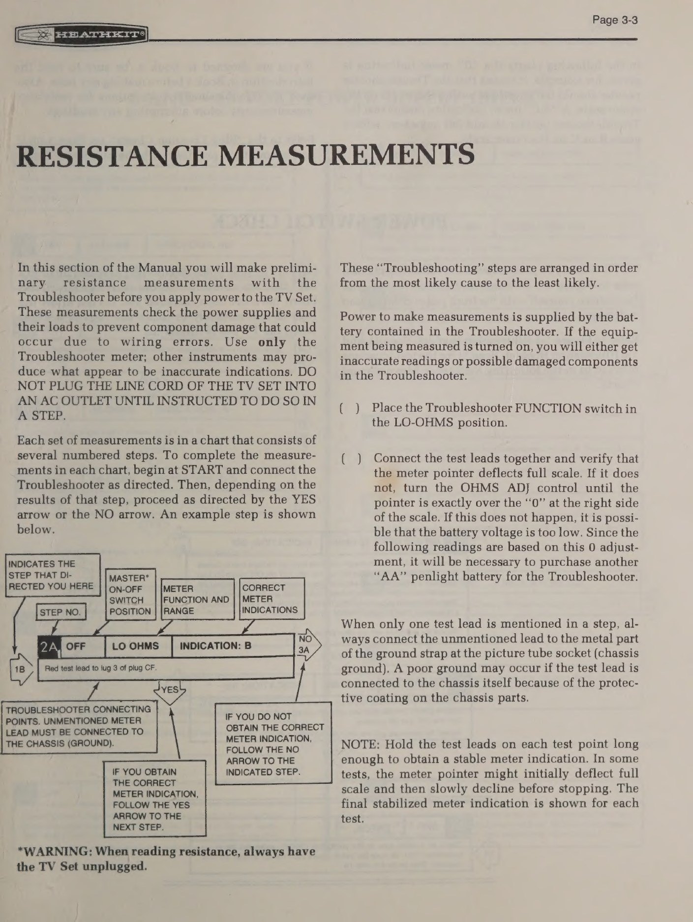
The manual’s first section is a set of flowcharts. With the line cord unplugged, the builder connects the Troubleshooter — the meter built into the set — across each power-supply rail and its load in turn, and follows a branching chart: obtain the expected indication and go to the next step; fail to obtain it and go to the numbered troubleshooting step for that rail. The supplies checked in Book Three are the −8 and −15 volt, −25 volt, 190 volt, 250 volt, 160 volt, 77 volt, 24 volt and 5 volt lines, with a separate check of the power switch.
Two instructions are worth repeating because they are easy to skip. The manual says to use only the Troubleshooter for these measurements, because other instruments “may produce what appear to be inaccurate indications” — the charts are written around the loading of that particular meter. And it says that the steps are ordered from the most likely cause to the least likely, which is a compact statement of how a Heathkit troubleshooting chart is meant to be read.
The purpose is stated plainly: these measurements “check the power supplies and their loads to prevent component damage that could occur due to wiring errors”. A shorted rail found with a battery-powered ohmmeter costs nothing; the same short found by the mains costs transistors.
4.2 First power-up
Only after the resistance charts does the set get plugged in, and even then the manual works through a chart of preliminary voltage readings with the picture-tube socket unplugged before the tube is allowed to light. A warning heads that chart: high voltages are present at many points, and any NO result means switching off at once.
Three things Heath’s manual takes trouble to tell a first-time owner are normal, and all three still alarm people today:
- Arcing. The manual says occasional snapping or arcing may be heard during the first two weeks. It happens between the elements of the colour picture tube and is normal while the tube ages in. It can trip the circuit breaker or change the channel; the remedy is to push the breaker’s red button back in.
- A blinking channel number. A channel entered in the display but not yet programmed on the channel-selection board makes the readout blink and the screen go black.
- A different channel after a cold start. The set remembers the last channel through the INSTANT ON/OFF switch, because the memory circuit stays powered; switch off at the MASTER ON/OFF switch and the memory loses its supply, so the set comes up on a random channel.
During the adjustments the manual has the builder pull transistor Q105 from the AGC/SYNC board, which disables the muting circuit so that the screen does not blank and the sound does not squelch while channels are switched. It goes back at the end. The same section suggests a large mirror behind the set, so that a person working at the back can watch the screen — a small piece of workshop advice that says a great deal about the job.
4.3 Programming the channels
The GR-2000’s tuning is only as good as its programming, and programming is a logic exercise with a field of pins rather than an electrical adjustment.
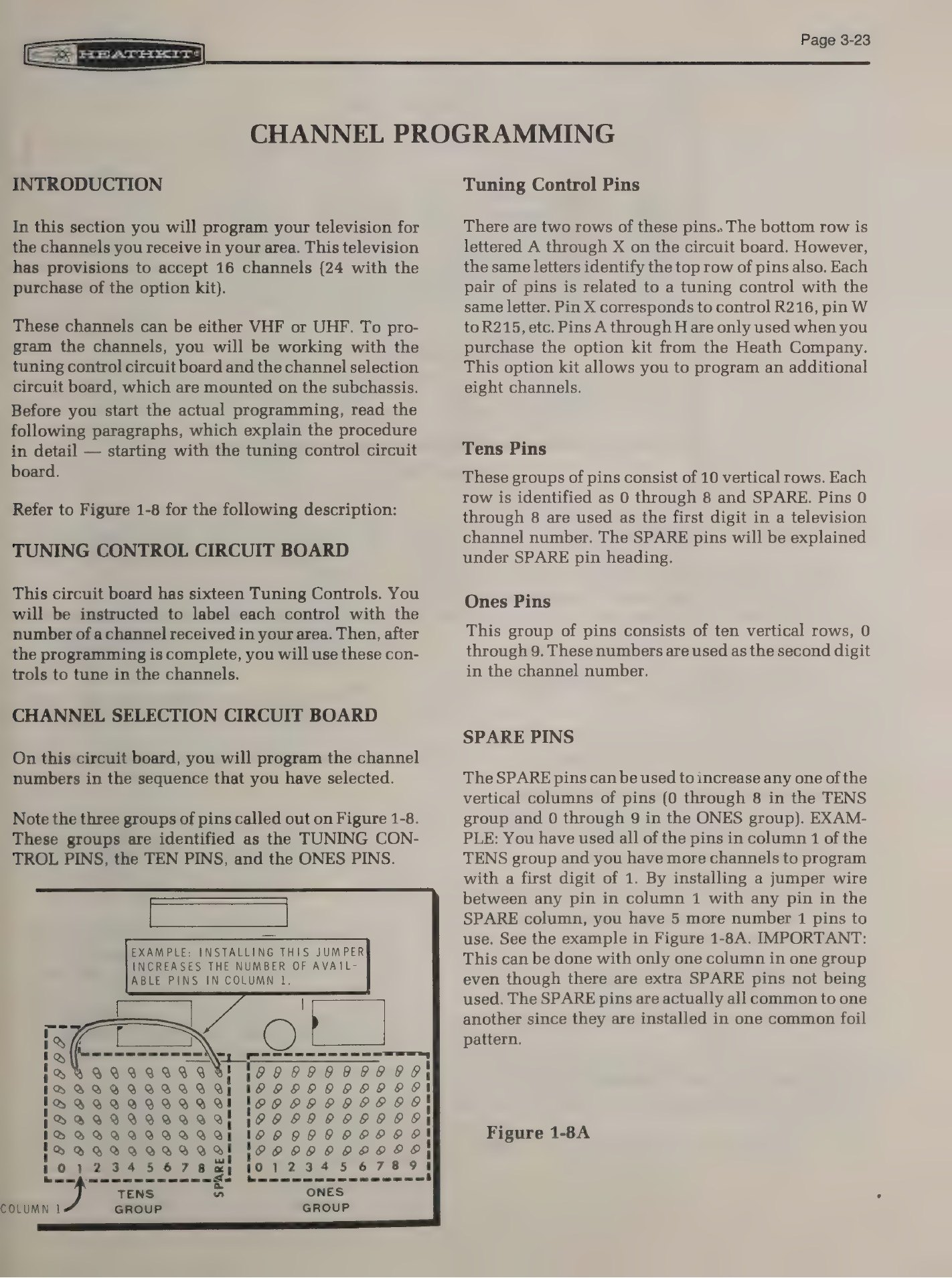
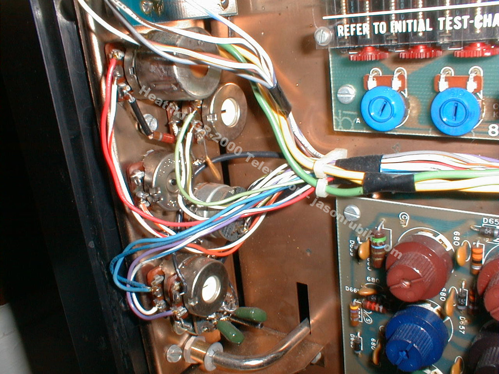
Two boards are involved, both on the sub-chassis. The tuning control board carries sixteen potentiometers, one per channel slot; each is labelled with a stick-on channel number from a sheet supplied with the kit, and each is set to the middle of its travel before tuning begins. The channel-selection board carries three groups of pins: the TUNING CONTROL pins, lettered to match the controls; the TENS pins, in ten vertical columns representing the first digit of a channel number; and the ONES pins, in ten columns for the second digit. A jumper from a slot’s tuning-control pin to a column in the TENS group and another to a column in the ONES group define what number that slot displays.
A neat detail shows how carefully the board was laid out for a domestic reality — several stations sharing a leading digit. A column of digit pins can run out; a SPARE column exists to extend one column in each group, all the SPARE pins being common to a single foil pattern. The manual spells out the limitation: the trick works “with only one column in one group even though there are extra SPARE pins not being used”.
With the numbers assigned, each slot is tuned by adjusting its potentiometer for the best picture on the station it is to carry, with automatic fine tuning switched off, and then a.f.t. is switched back on to hold it. Because the slots are independent of the channel numbers, the sixteen stations can be arranged in whatever order suits the household, and a favourite channel can sit in two slots so that it is never more than one press away.
4.4 Degaussing
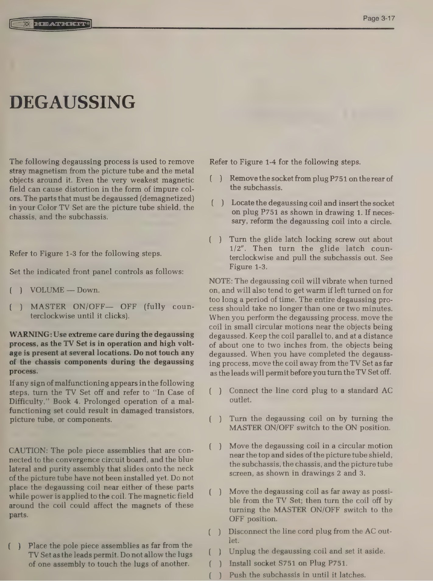
Colour purity depends on the three beams striking only their own phosphor dots, and any magnetised steel near the tube — the shield, the chassis, the mask — deflects them. The set degausses itself automatically at every cold start, but the parts have to be demagnetised once, deliberately, with the coil supplied in the kit.
The procedure is short and hedged with warnings. The coil is plugged into an a.c. outlet — it will hum — moved in circles over the face and sides of the picture tube, then withdrawn slowly to arm’s length before being switched off, so that the field decays gradually rather than leaving a residue. The manual is emphatic about what must not be degaussed: the pole-piece assemblies on the convergence board and the blue lateral and purity assembly on the tube neck are permanent magnets, and bringing the coil near them undoes the convergence. It also warns against leaving the coil energised too long.
4.5 Purity
Purity comes before convergence, because misplaced beams cannot be made to coincide usefully.
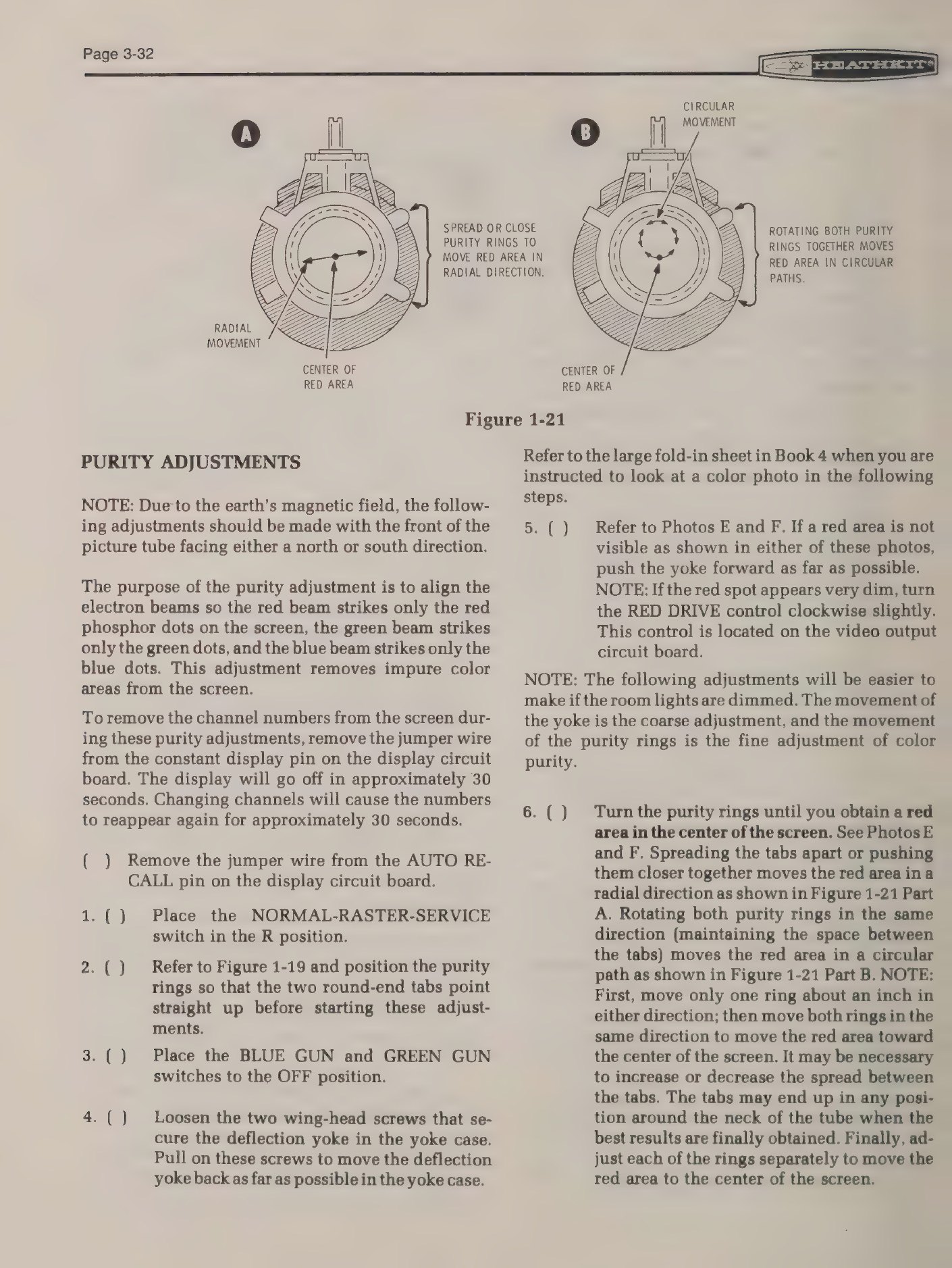
The set is positioned facing north or south — the earth’s field is enough to matter — and put into raster mode with the NORMAL-RASTER-SERVICE switch. With the green and blue guns switched off at the service board, the screen should show an even red field. The purity rings on the tube neck are rotated, together and against each other, and the yoke is moved forward or back on the neck until the red field is uniform. The other two guns are then checked in turn.
The on-screen digits get in the way of this, so the manual has the jumper pulled from the constant-display pin on the display board: the numbers then time out after about thirty seconds and stay away until a channel is changed. Small procedural touches like that are a reminder that the readout was a new problem as well as a new feature.
4.6 Static convergence
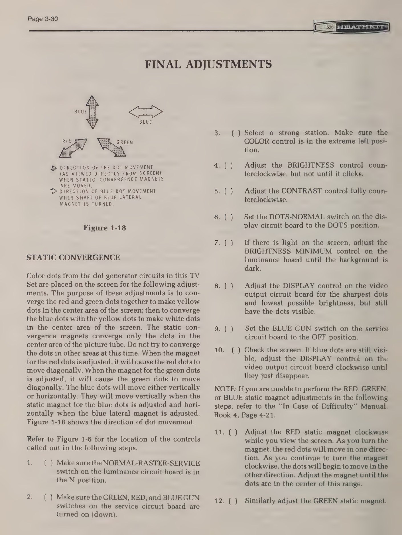
Now the dot generator earns its place. The DOTS/NORMAL switch replaces the picture with an array of small white dots generated inside the set, and the task is to make the red, green and blue dots coincide.
The order is fixed and it is the order that makes the job tractable: first converge red and green in the centre of the screen so that their dots merge into yellow, then bring blue onto the yellow so that the result is white. The static convergence magnets move the red and green dots diagonally; the blue static magnet moves blue vertically and the blue lateral magnet moves it horizontally. Only the centre of the screen is converged at this stage — the manual says explicitly not to try to fix the rest yet.
4.7 Dynamic convergence
Away from the centre the beams arrive at the mask at increasing angles, and correcting that is the job of the convergence board and its coils. The board is laid out in four rows of controls, each row responsible for one area of the screen — top, bottom, left and right — and the same sequence applies: red and green to yellow along the vertical and horizontal centre lines first, then blue onto the yellow.
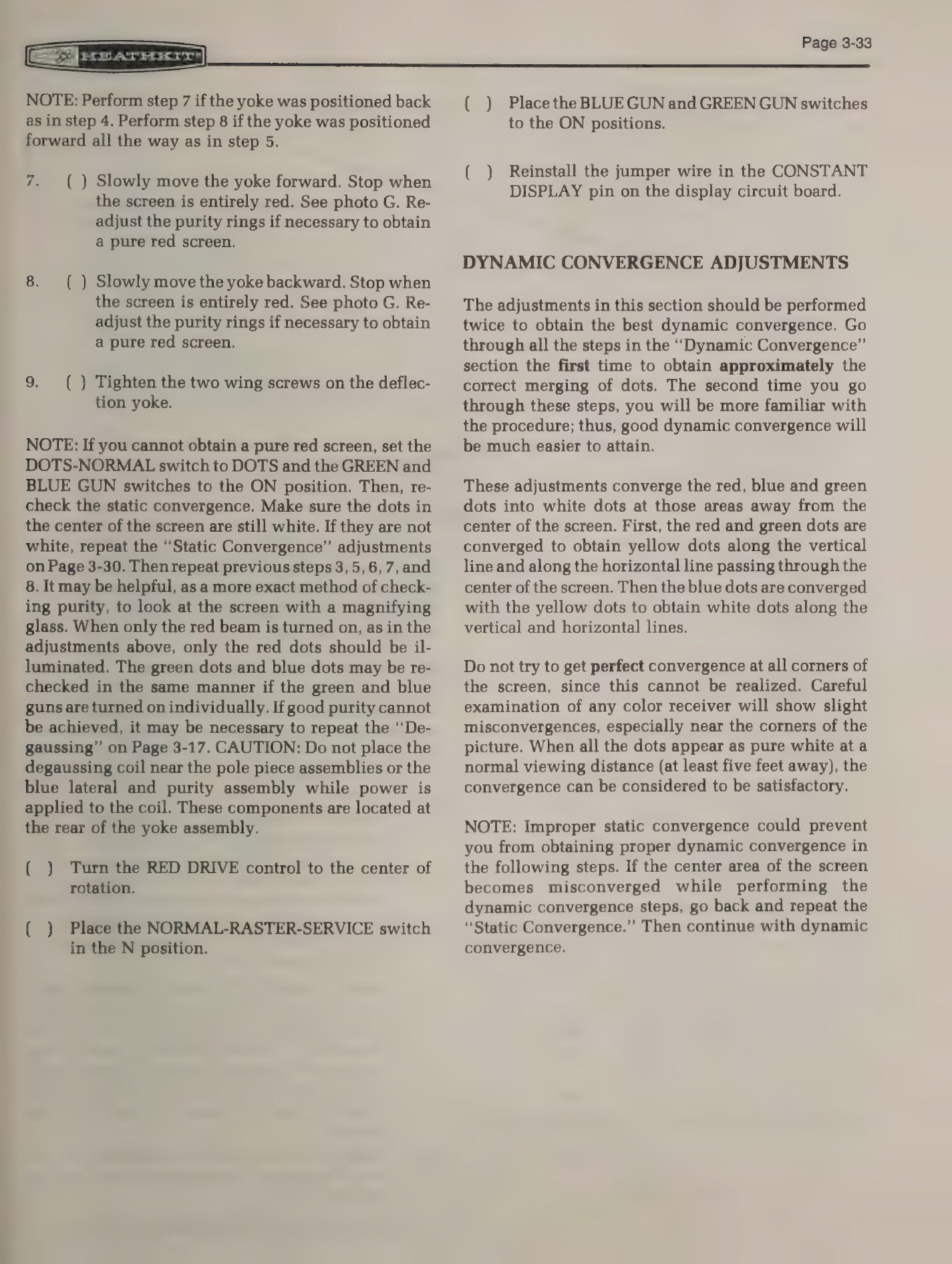
The manual’s two pieces of advice here are the ones that separate a satisfying afternoon from a maddening one. Go through the whole sequence twice: the first pass gets the dots approximately together, and the second, made with a feel for which control does what, gets them right. And know when to stop: perfect convergence in every corner cannot be had, that close examination of any colour receiver shows slight misconvergence near the corners, and that the job is done when the dots read as pure white from a normal viewing distance of five feet or more.
If the centre goes off while the outer areas are being set, the instruction is to go back and repeat the static convergence rather than to chase it with the dynamic controls.
Popular Electronics reported what the whole sequence cost in practice on a GR-2000: convergence was far easier than on most colour sets, crediting the built-in dot generator’s small, steady dots, and put the whole colour set-up at under an hour.
4.8 Grey-scale, final tuning and a.f.t.
With geometry settled, the screen controls (red, green and blue) and the drive controls are set so that the picture is neutral from black to white — the step Heath’s manuals call the kine bias and screen control adjustment. The high-voltage lockout circuit is then checked functionally, by jumpering two test points on the horizontal oscillator board to simulate excess high voltage and confirming that the picture cannot be pulled back into horizontal sync; the manual warns that the resistor involved gets very hot.
Finally the automatic fine tuning is aligned. A transistor is pulled from the U-V switching board to disable a.f.t. while the a.f.t. assembly itself is adjusted through the open chassis door, with a warning that voltage is present at several points on that door. Everything that has been removed for the procedures — the muting transistor, the a.f.t. transistor, the display jumpers — then goes back, and the set is ready for its cabinet.
4.9 Living with it
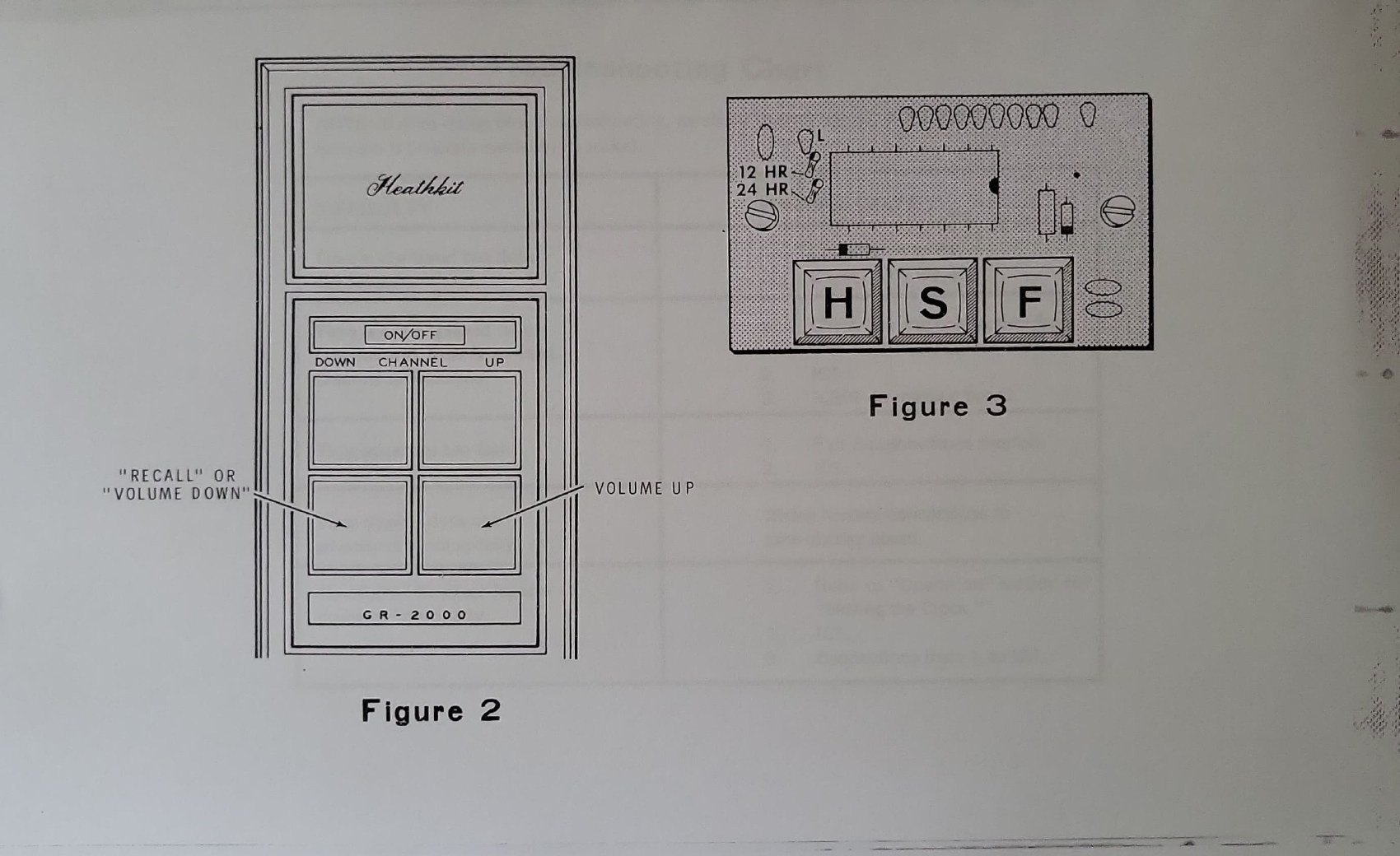
The controls the viewer met were deliberately few. On the front panel there were no tuning knobs at all: channel up, channel down, volume up and down, and, with the remote fitted, colour and tint. A full complement of secondary controls — volume, colour, tint, peaking, contrast, brightness, horizontal and vertical hold, height, a.f.t. on/off, tone, speaker on/off and the drawer latch — sat behind the panel for the owner rather than the viewer.
The on-screen display was configurable in a way that has a modern flavour. The channel number could be set to stay for up to about a minute and a half or to remain permanently; it reappeared at each channel change, at a touch of RECALL, or — with the remote — at a touch of the volume button. Its position on the screen was adjustable, and with the clock fitted the time appeared directly below the channel number in the same one-inch digits, in 12- or 24-hour form, with or without seconds. The clock ran whether or not the set was on.
Two practical notes from the manuals round out the picture. The hi-fi output was a real output, intended to be fed to a separate amplifier, and with the remote fitted its level followed the remote’s volume control. And the instructions for the aerial are more than boilerplate: a set with sixteen preset channels and no fine-tuning knob depends on a decent signal, and Heath devoted several pages to VHF and UHF aerial choice and installation.
Sources
- Heathkit GR-2001 Color Television, Book Three: Adjustment and Operation, 595-1865-06 (1976), Internet Archive — resistance and voltage charts, degaussing, purity, static and dynamic convergence, high-voltage lockout check, a.f.t. alignment, channel programming.
- Heathkit GRA-2000-1 TV Clock Accessory, assembly and operation manual, Internet Archive.
- “Heathkit Model GR-2000 Digital Color TV Receiver”, Popular Electronics, April 1974, pp. 77-80.
- Larry Steckler, “Heathkit’s new digital color TV”, Radio-Electronics, February 1974, pp. 33-37, 78-80.
- Heathkit catalogue 800/95, March 1974 and Christmas 1975 catalogue (controls and display options).
Comments (0)