GR-2000 Color Television · Volume 5
Restoration and Common Faults
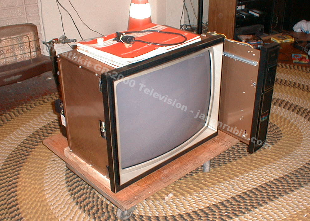
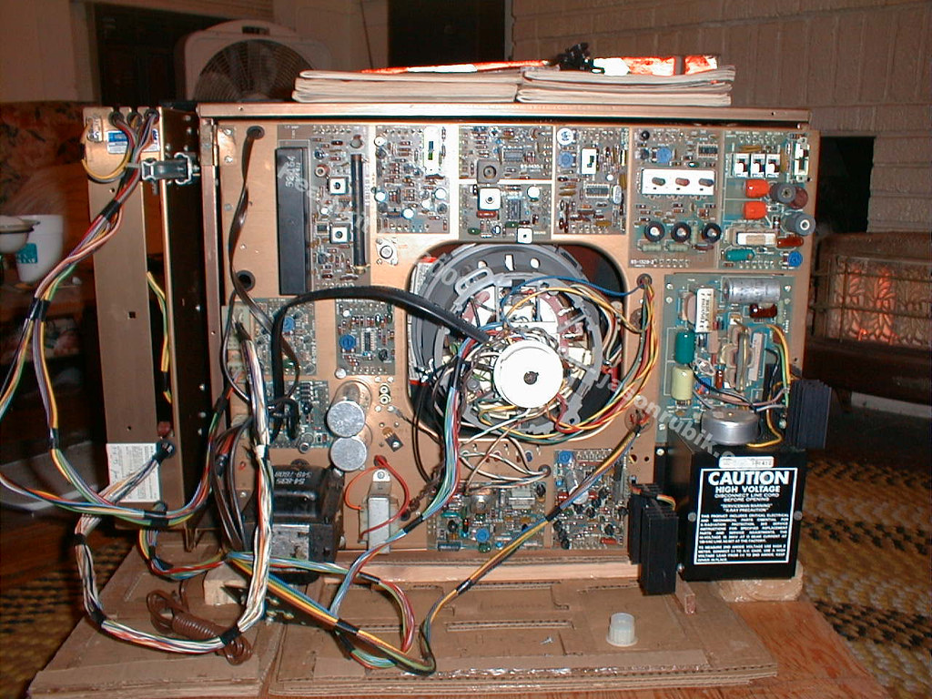
A GR-2000 that has sat in a garage since the Reagan administration is a large object containing a 26,000-volt supply, a picture tube that holds its charge for weeks, several hundred capacitors, a picture tube that cannot be replaced and a set of custom MOS integrated circuits that cannot be bought. It is also one of the most repairable televisions of its generation, because Heath designed it to be repaired by the person who built it: every semiconductor is in a socket, every function is on a plug-in board, and the instruments needed to set it up are in the cabinet. This volume covers the safety rules, the faults that are known to turn up, the parts problem and the modifications people make.
Nothing here replaces the manual. Anyone working on one of these sets should have the assembly manual for their own model open beside them.
5.1 Safety, stated plainly
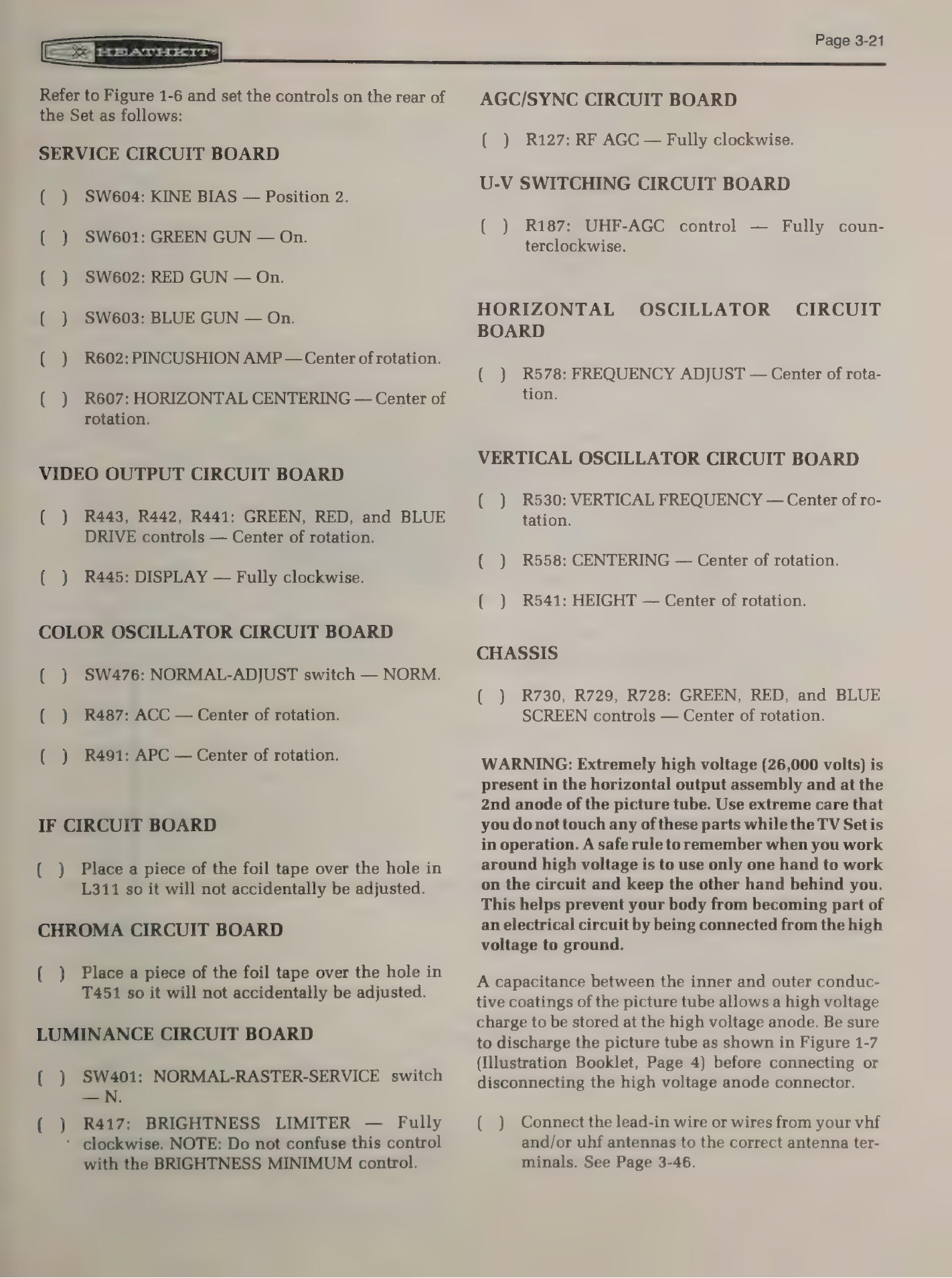
The high voltage is 26,000 volts. Heath’s own warning in the manual for the sister set is plain: 26,000 volts is present in the horizontal output assembly and at the picture tube’s second anode, neither may be touched while the set is running, and the working rule around high voltage is one hand on the circuit with the other behind your back, so that no current can pass through the body to ground (GR-2001 Book Three, p. 3-21).
The picture tube stores a charge after the set is switched off. The capacitance between the inner and outer conductive coatings holds a charge at the anode connector; the manual instructs that the tube be discharged before the anode connector is put on or taken off. A grounded lead and a high-value resistor on an insulated probe, applied under the anode cap and left in place while working, is the standard method.
Mains voltage is present in places that do not look like it. The manual warns that voltage is present at several transistor cases around the chassis and at several locations on the chassis door. The set is transformer-operated — the manual names power transformer T701 — so the chassis is not tied directly to one side of the mains as it is in a live-chassis portable, but that is not a licence to be casual about the a.c. side of the power supply.
The picture tube is an implosion hazard. Treat the neck as breakable, never lift the tube by it, and wear eye protection when handling a bare tube.
5.2 X-radiation: why the lockout circuit exists
A colour television that runs its final anode above the design voltage emits X-rays. This was a public controversy in 1967-1969 after excessive emission was found in some factory sets, and it produced a federal standard: under the Radiation Control for Health and Safety Act, the Department of Health, Education and Welfare issued a performance standard for television receivers, now 21 CFR 1020.10, limiting exposure to 0.5 milliroentgen per hour measured 5 cm from any point on the outside of the receiver, under adverse operating conditions. It applies to receivers with cathode-ray tubes manufactured after 15 January 1970 — which is to say, to every Heathkit colour set from the solid-state generation onwards.
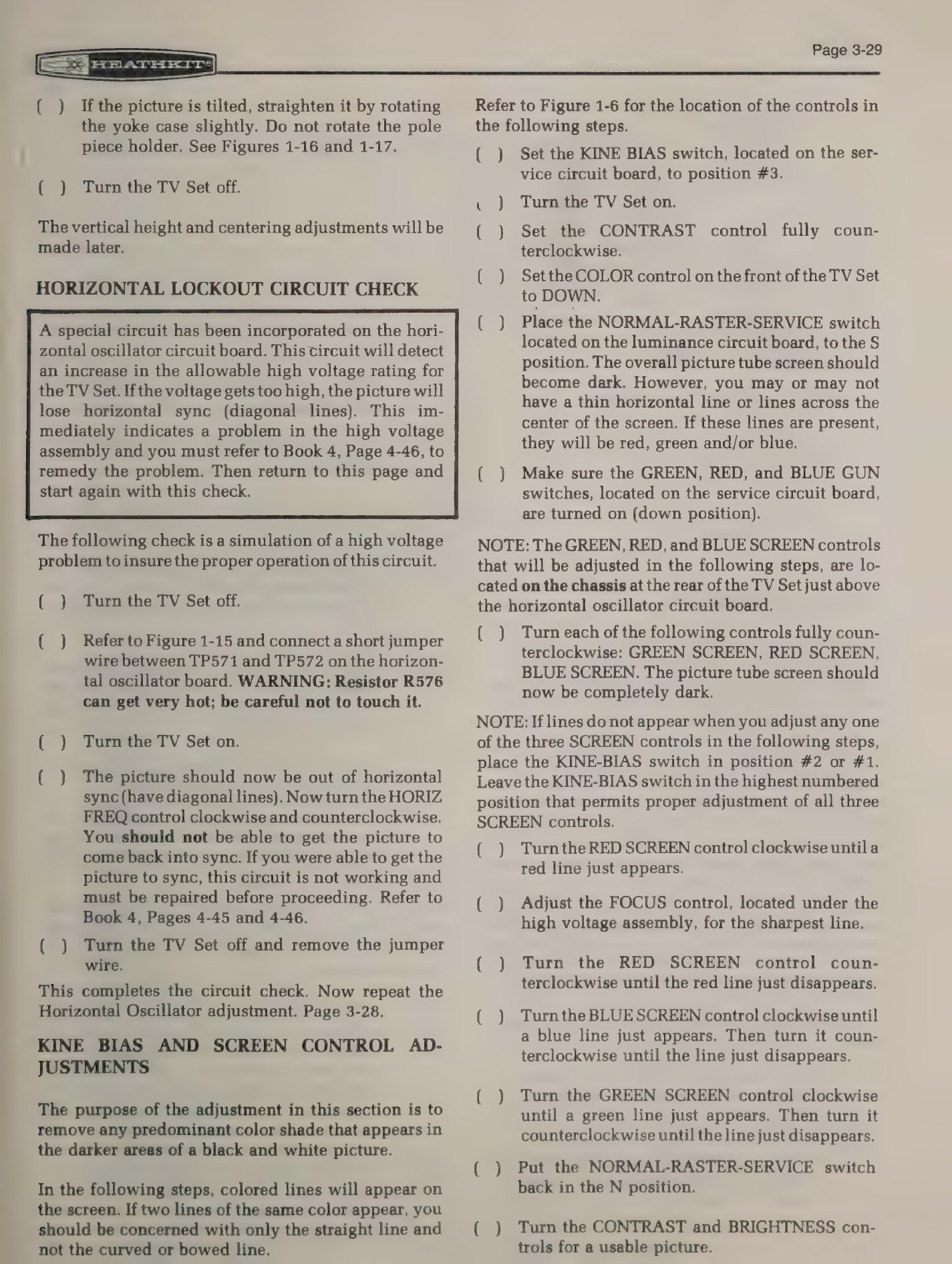
The design consequence is the high-voltage lockout circuit on the horizontal oscillator board. Heath’s own description: a circuit on the horizontal oscillator board watches for the high voltage rising past its allowed figure, and answers by throwing the picture out of horizontal sync into diagonal lines — a visible signal that something is wrong in the high-voltage assembly. The manual then gives a test that simulates the fault by jumpering TP571 to TP572, checks that the picture cannot be pulled back into sync with the horizontal frequency control, and warns that resistor R576 gets very hot during the test.
Three rules follow for a restorer:
- Do not defeat the lockout. A set that will not hold horizontal sync and cannot be brought back with the hold control is reporting a high-voltage fault. Disabling the circuit to get a picture is the one modification that can make the set genuinely dangerous to sit in front of.
- Measure the high voltage with a proper high-voltage probe when the set is returned to service, and set it to the figure in the manual rather than to what looks brightest.
- Keep the regulation circuits honest. Drifted components in the horizontal output and high-voltage regulation are the usual reason a set runs high, and are exactly what fifty years of ageing produces.
5.3 Bringing one back to life
Standard vintage-electronics practice applies and is not in the Heath manual, which assumes a new set: do not simply plug in a television that has been in storage. The usual sequence is to inspect for rodent damage and corrosion, check for obvious shorts, bring the set up slowly on a variac with a dim-bulb limiter in series so that a shorted rectifier or a leaky capacitor announces itself as a glowing lamp rather than as a fire, and monitor the low-voltage rails before allowing the set to run at full line voltage.
The GR-2000 has one real advantage here. Heath’s own pre-power resistance charts, made with the built-in meter, are exactly the checks a restorer wants before applying power, and they are written as flowcharts that name the likely cause of each failure. Working through Book Three’s resistance section on a set that has been in storage is a better use of an hour than any amount of guessing.
5.4 Faults that are known to turn up
The most detailed public account of a GR-2000 restoration is a VideoKarma thread in which the owner of a low-hours set, built in the early 1980s from a kit with 1976-dated parts, worked through it in public. The faults reported there, together with what the manuals imply, give a useful list.
Convergence coil cores. The adjustable inductors on the convergence board have plastic hexagonal tuning cores, and on this set they “just had their plastic hex screws disintegrate over the years”. A convergence board whose cores crumble cannot be set up, and the parts are not made; restorers salvage them from donor boards.
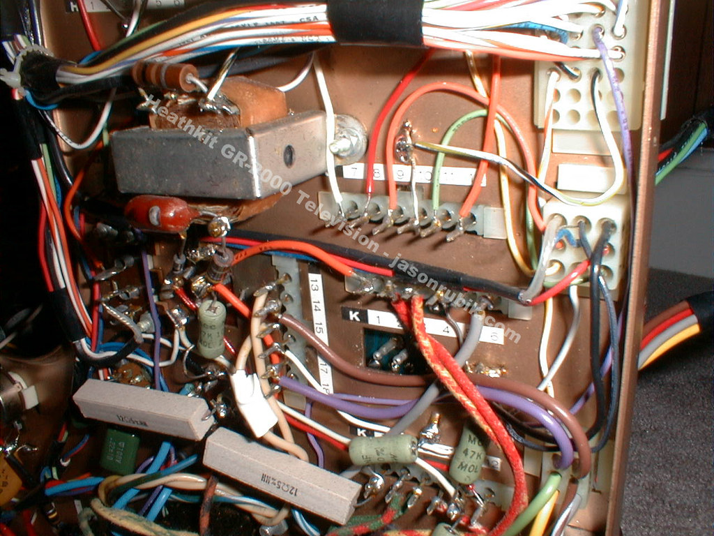
Cold and fatigued solder joints. Loose joints were found on the antenna connections. In a kit set every joint was made by hand by an amateur, and a fifty-year-old joint that was marginal when new is a routine find. The plug-in boards’ edge connectors also benefit from cleaning.
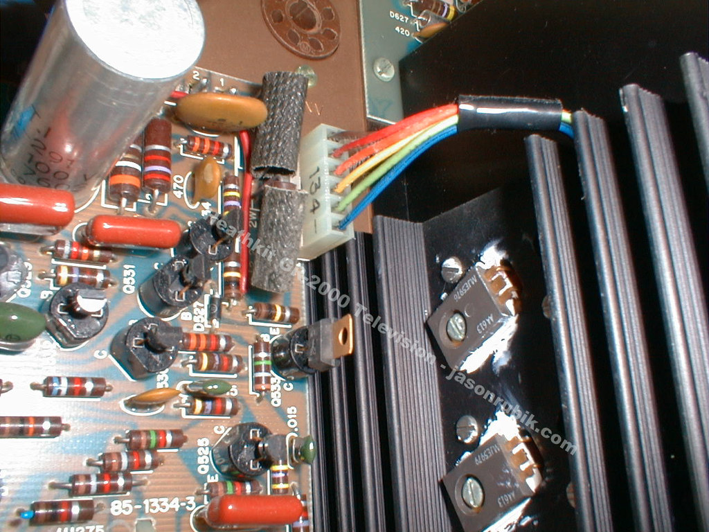
A burnt carbon-composition resistor on the horizontal output board. Carbon composition resistors in hot, high-stress positions drift high or char; the horizontal output assembly is where they work hardest.
Degaussing circuit components. The thermistor and the PTC posistor in the automatic degaussing circuit both failed on the set in that thread, and the owner had to wait for new-old-stock parts. A failed posistor can leave the degaussing coil energised or, more often, stop the automatic degauss working altogether.
Reinstallation errors. After recapping, a board put back misaligned cost that set its vertical deflection. With twenty boards and multi-way connectors this is a self-inflicted fault worth guarding against by photographing everything before disassembly.
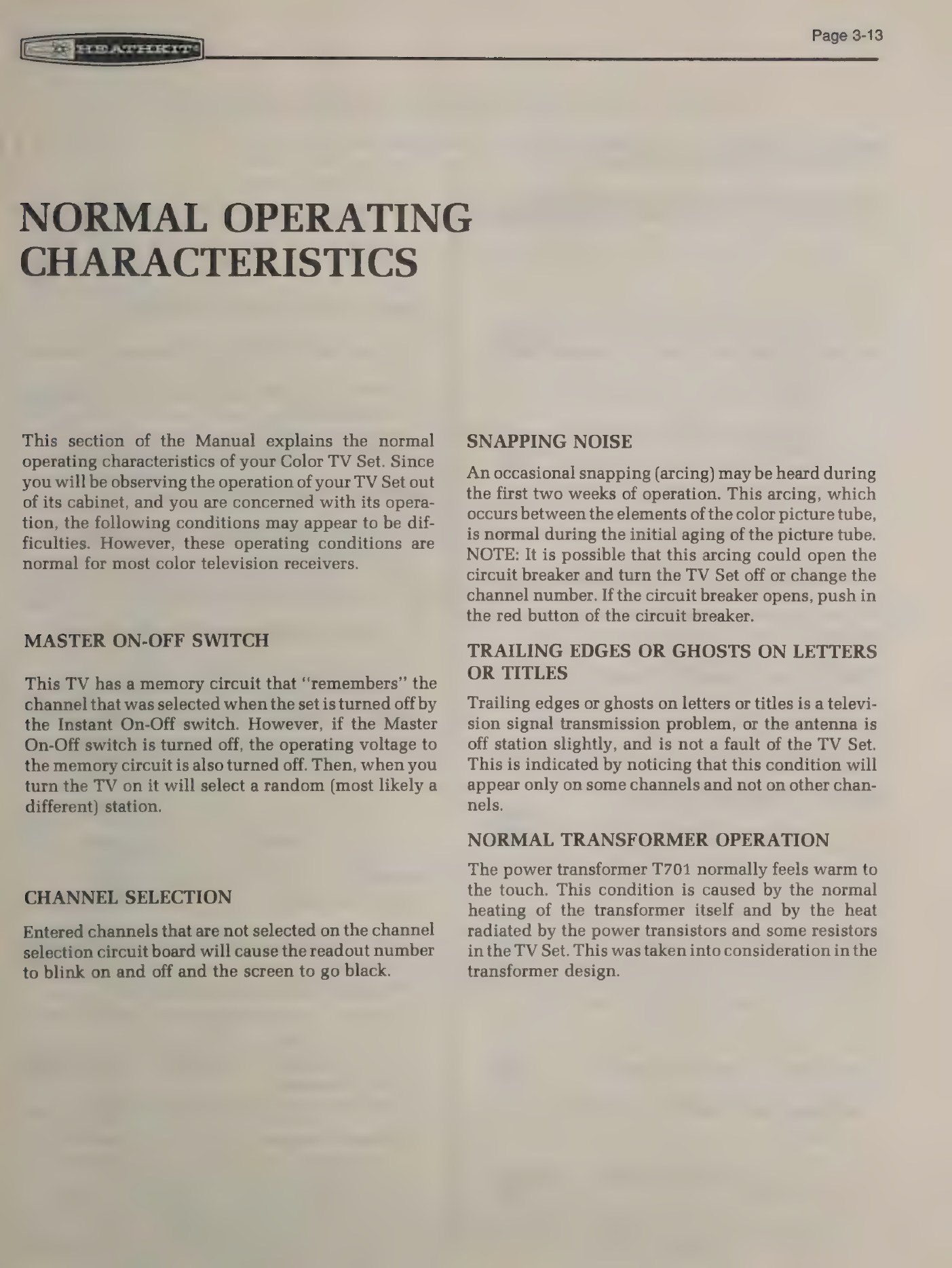
Apparent faults that are not faults. The same thread records a horizontal jump traced to the head-switching pulse of a video recorder interacting with the set’s automatic frequency control — it disappeared when an over-the-air converter box was used instead. A 1970s television fed from modern sources will show artefacts that are not its own doing. Heath’s manual similarly lists arcing during the first weeks of picture-tube life, a blinking channel number on an unprogrammed channel, and a warm power transformer as normal.
5.5 The parts problem
Three categories of part, in ascending order of difficulty.
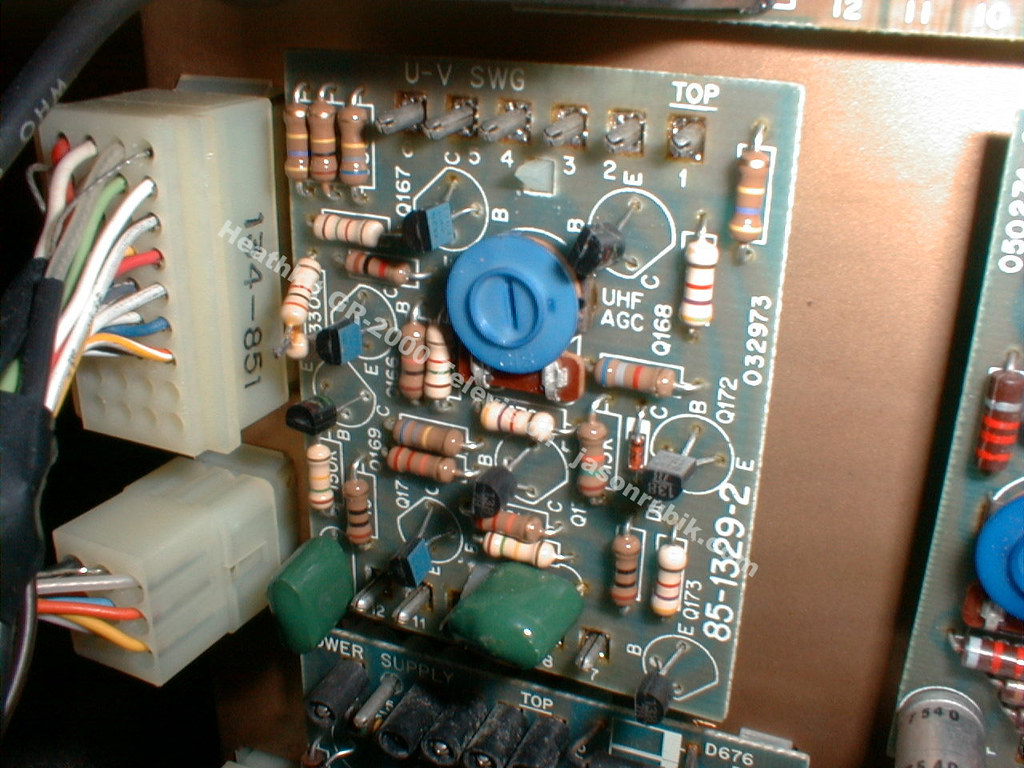
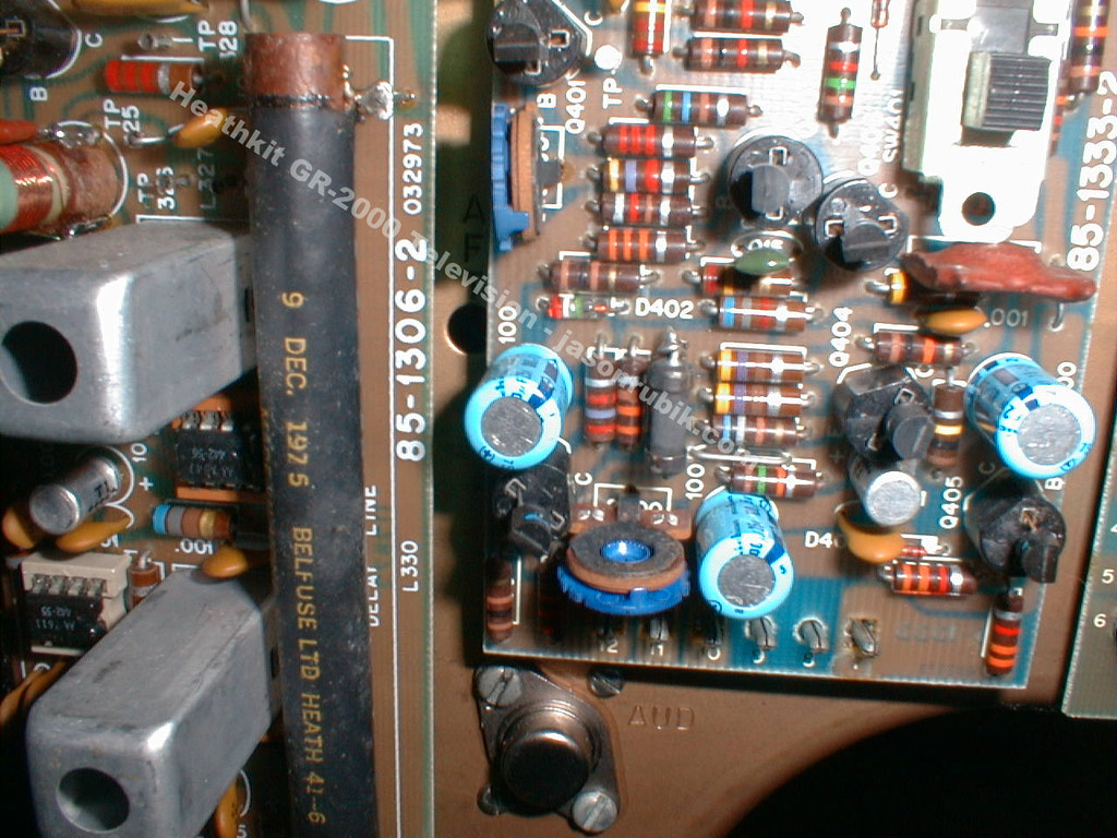
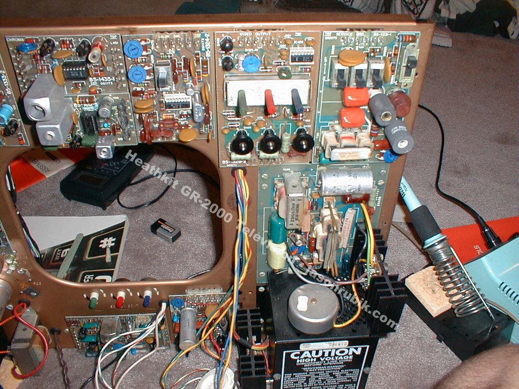
Ordinary components. Resistors, capacitors, small-signal transistors and diodes are all replaceable with modern equivalents. The GR-2000 is a good candidate for recapping because the boards come out, and because the semiconductors’ sockets mean the boards can be worked on without desoldering active devices.
Heath-specific assemblies. The sealed ten-section i.f. filter, the varactor tuners, the convergence board’s coils and the deflection components have no catalogue equivalents. Heath’s own answer in the 1970s was the module exchange — 48-hour service at the factory or any Heathkit Electronic Center, and after the warranty a flat $5.00 per module — and that has been gone since the 1990s. Donor sets are the supply.
The custom MOS integrated circuits. The character generator (IC301), the clock IC (Heath part 443-617) and the other custom devices are the irreplaceable parts. No source of replacements is known. A set whose readout IC has failed can still work as a television, with its channel display gone; that is the one failure that would take away the feature the set exists for.
The picture tube. The 25-inch tube is the practical limit on restoration. Only a handful of firms still rebuild cathode-ray tubes at all — the Early Television Museum notes that where hundreds of companies rebuilt picture tubes in the 1950s and 1960s, “today picture tubes outlast the average TV set, and only a few companies still rebuild them” (earlytelevision.org) — and shipping a 25-inch colour tube is expensive and risky. A weak tube can sometimes be improved with a rejuvenator; a tube with a broken neck or lost vacuum ends the set as a television.
5.6 Modifications, period and modern
Heath itself offered the upgrades that mattered at the time: the clock module and the remote control could be added at any point after the set was built, and the assembly manuals for both are written on the assumption that the television already exists.
The modification most often wanted today is a video input. A GR-2000 has no line input — in 1974 there was nothing to plug in — so everything must arrive as VHF or UHF r.f. The two approaches are the easy one, a modulator or a digital-to-analogue converter box feeding the aerial terminals on a programmed channel, and the invasive one, injecting video and audio at the appropriate points in the chassis. A schematic for a video-input modification to this set was shared in the VideoKarma thread cited above. Anyone doing it should remember that the on-screen readout is inserted downstream, in the video output stages, so the channel display will still work — and will still show whatever channel the tuner is parked on.
The second common wish is to preserve the digital functions. Since the custom ICs are unobtainable, the sensible modern conservation measure is to photograph and document the jumper configuration of the readout board and the channel-selection board before anything is disturbed, and to keep the set’s original sheet of stick-on channel numbers with it.
5.7 Collecting today
The GR-2000 is an unusual collectable: a mass-market consumer product made in unknown but substantial numbers, of which every surviving example was assembled by an individual. That makes condition wildly variable in a way that factory sets are not — as one forum member put it in a thread about Heathkit televisions generally, the result was “only as good as the builder was skilled” (VideoKarma, “Heathkit TVs”).
Four practical observations.
Weight and bulk set the market. A 112-pound chassis in a floor cabinet is a local pickup, not a shipped purchase, and that keeps prices low and regional. Cabinets in good condition are scarcer than chassis, since Heath’s own final cabinet order went in on 1 December 1982.
Unbuilt kits exist. Complete unbuilt GR-2000 kits have changed hands, sometimes with the GD-1999 television game kit alongside. An unbuilt kit is the only way to have the original experience, at the cost of fifty-year-old electrolytics that have never been formed.
Manuals are the limiting document. No free scan of the GR-2000’s own five books has been found; the surviving free scans are of the GR-2001’s Book Three and the clock accessory manual. Paper sets appear regularly on the second-hand market and reprints are sold commercially. The full position is set out in the reference volume.
Provenance is in the boards. Kit-built sets carry no serial number that means anything, but the boards are dated, the stick-on channel numbers record where the set lived, and a builder’s name is sometimes pencilled inside the cabinet. Those are the things to photograph before restoration, not after.
Sources
- Heathkit GR-2001 Color Television, Book Three: Adjustment and Operation, 595-1865-06 (1976), Internet Archive — high-voltage warnings, picture-tube discharge, horizontal lockout check, normal operating characteristics.
- “Heathkit GR-2000 Solid State Color TV”, VideoKarma forum thread — restoration account and fault list.
- “Heathkit TVs”, VideoKarma forum thread — collector opinion on Heathkit television sets.
- 21 CFR 1020.10, Television receivers, Electronic Code of Federal Regulations.
- “CRT Rebuilding”, Early Television Museum.
- Heathkit catalogue 810/72, 1972 (module exchange terms) and Christmas 1982 catalogue, p. 86 (final cabinet order).
Comments (0)