DX-100 Transmitter · Volume 2
How It Works
Fifteen valves, two transformers, two chokes and a modulation transformer make one signal. The DX-100’s circuit is conventional for 1955 in every individual stage and unusually complete as a whole: a stable oscillator, three stages of radio-frequency amplification, a four-stage speech chain that plate-modulates the last of them, and three power supplies to feed the lot. Nothing in it is clever for its own sake. What distinguishes the design is the attention paid to two problems that were making amateur transmitters unwelcome in 1955 - frequency drift and television interference - and the fact that both answers are structural rather than added afterwards. This volume follows the signal through the rig, then follows the power, then looks at what the layout is doing.
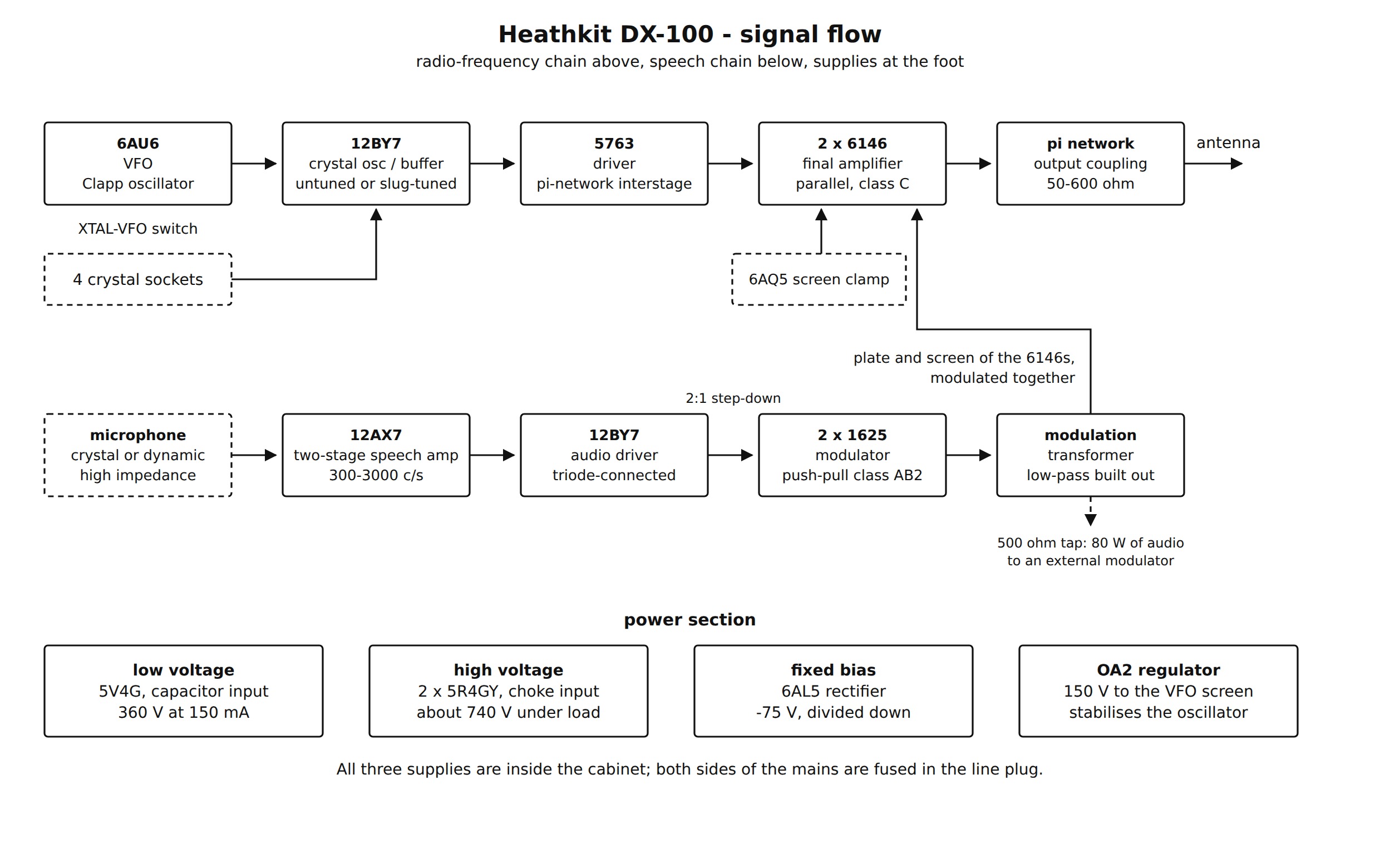
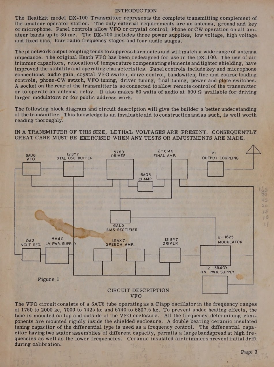
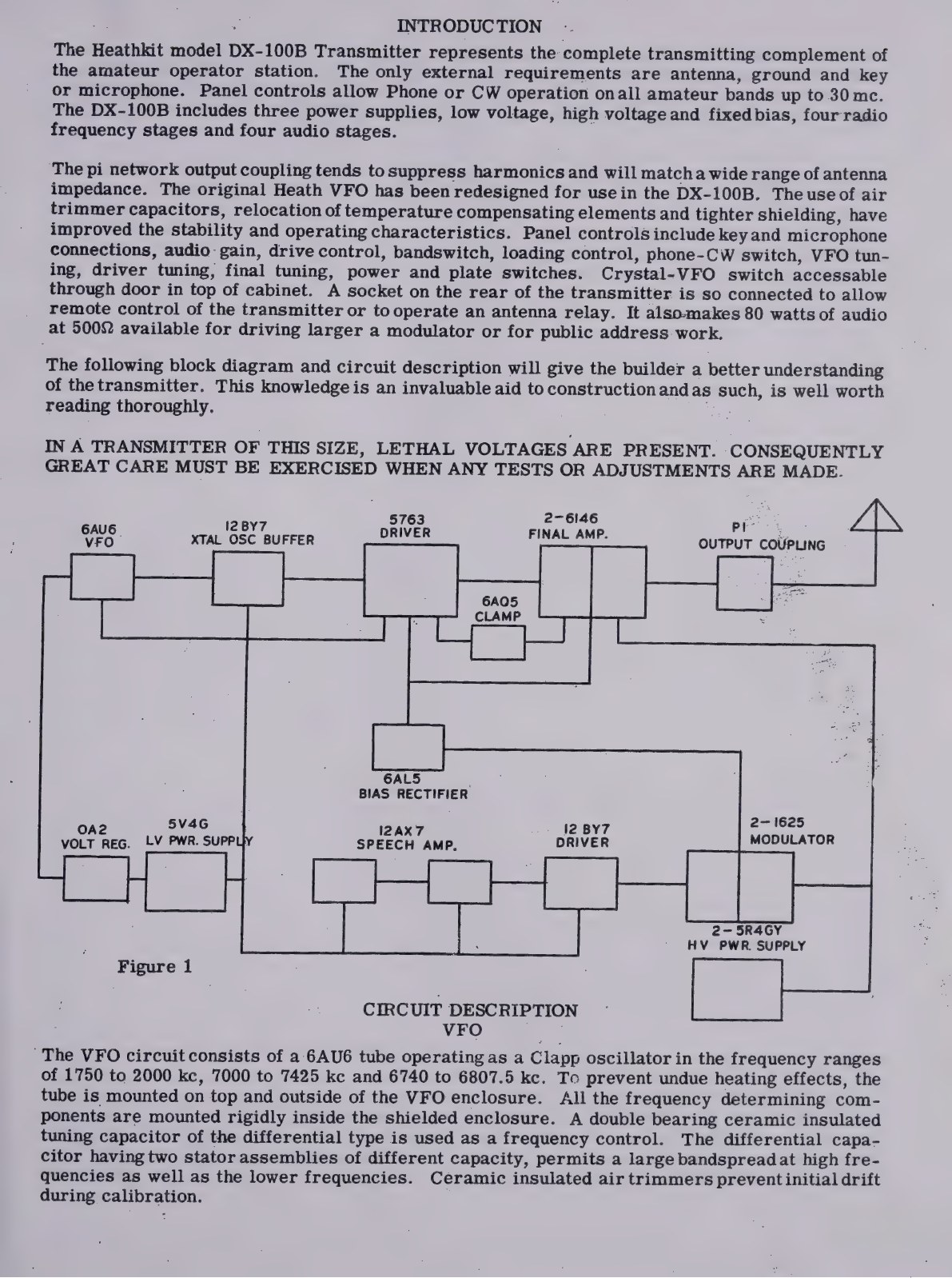
figs/make_diagrams.py, from the DX-100 assembly manual, https://archive.org/details/heathkittransmit00unse_02.1 The manual’s own block diagram
Heath put a block diagram and a page of circuit description at the front of the manual, before a single part was picked up, and told the builder to read it: “This knowledge is an invaluable aid to construction and as such, is well worth reading thoroughly.” The same page carries the sentence that every owner should still read first - “IN A TRANSMITTER OF THIS SIZE, LETHAL VOLTAGES ARE PRESENT.”
2.2 The VFO
The oscillator is a 6AU6 pentode in a Clapp circuit - a series-tuned Colpitts - working as an electron-coupled oscillator, with the screen grid acting as the oscillator anode and the true anode coupled to it only through the electron stream. The manual’s justification for the arrangement is drift: a Clapp presents a very low impedance at resonance for the grid to look into, which minimises the effect of changes in valve capacitance on frequency, and the large capacitive divider the Colpitts needs further swamps it. Electron coupling then isolates the oscillator from whatever the following stage is doing, so that loading changes do not pull the frequency.
The physical construction is doing as much work as the circuit. The frequency-determining parts sit rigidly inside a shielded enclosure; the valve is mounted on top of it, outside, so that its heat does not reach them. The tuning capacitor is a double-bearing, ceramic-insulated differential type with two stator sections of different capacitance, which is what gives the dial a usable spread at both ends of the range. The coils are wound with Litz or double-cellulose wire on heavy ceramic forms, doped and baked, for high Q and low drift. Temperature-compensating capacitors sit close to the coils so that as the coil inductance rises with heat, the compensator capacitance falls: the two effects cancel and the frequency stays put. The screen supply is held at 150 volts by an OA2 regulator (DX-100 manual, pp. 3-4).
The VFO covers three ranges, switched by a wafer inside the compartment that is driven from the main bandswitch by an interrupted mechanism, so that the oscillator range always matches the band in use:
Table 1 — The VFO covers three ranges, switched by a wafer inside the compartment that is driven from the main bandswitch by an interrupted mechanism, so that the oscillator range always matches the band in use
| VFO range | Bands it serves | Multiplication to the output |
|---|---|---|
| 1750-2000 kc | 160 m, 80 m | x1, x2 |
| 7000-7425 kc | 40, 20, 15, 10 m | x1, x2, x3, x4 |
| 6740-6807.5 kc | 11 m | x4 |
The DX-100B manual adds the dial spreads that this buys the operator: four inches of dial for 1750-2000 kc, five inches for 3500-4000, four and a half for 7000-7300, two and a quarter for 14.000-14.350 mc, one and three-quarters for 21.000-21.450, one and one-eighth for 26.960-27.230 and four inches for 28.000-29.700 (DX-100B manual, p. 3). Twenty metres reads about 155 kc to the inch; that is the practical limit of the mechanism, and it is why a DX-100 owner still ends up asking the other station for a frequency check.
2.3 Crystal oscillator, buffer and driver
The next valve, a 12BY7, does two jobs depending on the position of the XTAL-VFO switch. In the first four positions a crystal is connected between its grid and screen, making a modified Pierce oscillator - a grounded-cathode Colpitts in which the grid-cathode and screen-cathode capacitances form the divider. In the fifth position the crystals are out of circuit, the VFO output is fed to the grid, and the stage is simply a buffer amplifier. The same switch opens the 6AU6 cathode circuit in any crystal position, so the VFO is dead when crystals are in use.
Its anode circuit is where the band logic lives. On 160 and 80 metres it is untuned. On 40, 20 and 15 metres it is slug-tuned to 40 metres; on 11 and 10 metres it is slug-tuned to 20 metres. An untuned choke and the two slug-tuned coils sit in series from B+ to the anode, and one wafer of the bandswitch shorts out whichever coils are not wanted (1956 catalogue, p. 38; manual p. 4). Frequency multiplication is thus shared between this stage and the 5763 driver that follows it, and the final amplifier never multiplies.
The 5763 driver runs with a combination of fixed and grid-leak bias: enough fixed bias to keep it from drawing anode current with the key up, with the operating bias developed by drive. Its screen voltage is set by the front-panel DRIVE potentiometer, which is how the operator controls the grid drive to the final. A permanent shunt in its cathode circuit makes the meter read 0-50 mA in the DRIVER position. The coupling from driver to final is a pi network with a variable input capacitor and a fixed output capacitor, the inductance tapped by the bandswitch. Heath’s reason for using a pi network between stages rather than a simple tuned transformer is harmonic suppression: the fixed output capacitor appears from the final’s grid to ground and shorts the higher harmonics before they can be amplified.
2.4 The final amplifier
Two 6146 beam tetrodes in parallel run at about 740 volts, class C, with fixed plus grid-leak bias. Parallel rather than push-pull keeps the tank circuit simple - one pi network, one tuning capacitor, one tapped coil - at the cost of a slightly awkward layout, since both valves’ grids and anodes must be tied together with short leads.
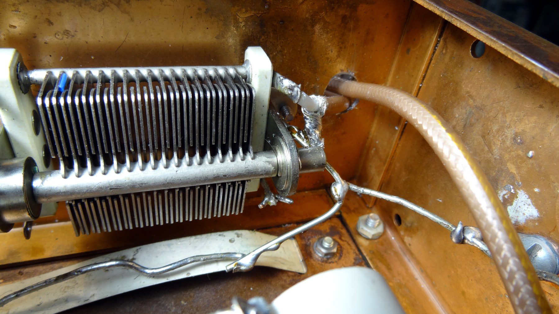
The tank is a pi network with a 350 pF variable on the input side, a tapped inductance selected by the bandswitch, and, on the output side, four fixed capacitors of 200, 400, 600 and 800 pF switched in combination by the COARSE LOADING control in 200 pF steps from 0 to 2000 pF, with a 250 pF variable as FINE LOADING to fill the gaps. The whole range is 15 to 2250 pF, which is what allows the manual to claim a match to any non-reactive load from 50 to 600 ohms.
Screen voltage for the 6146s is dropped from the anode supply through a resistor, which matters for two reasons. It is what makes the screens swing with the anodes when the plate supply is modulated - a tetrode must have its screen modulated as well as its anode, or the modulation is badly non-linear - and it is what the clamp valve acts on. The 6AQ5 clamp has its anode on the 6146 screens, its cathode grounded and its grid tied to the final’s grid circuit. With drive present, the bias developed keeps it cut off. If drive disappears - a crystal fails, the driver stops, the operator switches to an unused crystal position - the clamp grid goes to zero, the valve draws heavily and pulls the screens down, protecting the finals. Because the fixed bias on the 6146 grids would keep the clamp cut off too, Heath applies a small positive voltage to the clamp grid to cancel exactly the fixed bias and not the operating bias, so that the clamp responds to the loss of drive only (manual, pp. 4-5).
The two 6146s are sub-mounted on a separate plate. That plate does two jobs at once: it shields the grids from the output circuit, and it turns the space around the valves into a chimney so that air is drawn up past them. Aluminium heat-dissipating anode caps were supplied in the kit - the catalogue calls them one of the “extras” - and they are the first thing to look for on a used rig, because they are easily lost.
2.5 The speech chain and the modulator
A single 12AX7 provides two resistance-coupled triode stages, enough gain for a crystal or dynamic microphone. The audio bandwidth is deliberately narrowed at both ends: the coupling capacitors are only 500 pF, presenting a high reactance to low frequencies, and everything above about 3000 c/s is dealt with in the modulator stage. Heath’s statement of the trade is unambiguous - in amateur communication it is “desirable to sacrifice fidelity in favor of narrow bandwidth and confine the power transmitted to voice frequencies”.
The 12BY7 audio driver is triode-connected to present a low impedance to the modulator grids, and it feeds them through a 2:1 step-down transformer. This matters because the 1625s run class AB2, in which the grids draw current on peaks; the driver must therefore deliver power, and it must do so from a source stiff enough that the drive does not collapse as the load swings.
The modulators are a pair of 1625s in push-pull. The 1625 is an 807 with a 12.6-volt heater and a seven-pin socket, made in quantity for wartime ARC-5 transmitters and consequently cheap and everywhere in 1955; the choice of a 12-volt valve is also why the DX-100’s filament winding is 12.6 volts centre-tapped. The pair is capable of about 120 watts but is normally run at 80 to 90, with series resistors in the grid circuits preventing the grids from swinging too far positive and holding the output below the maximum obtainable.
Two details in the modulator are design decisions rather than accidents. The primary of the modulation transformer is a higher impedance than the 1625s would normally work into, which introduces deliberate high-level speech clipping and so raises average modulation. To keep that clipping from splattering, the transformer is “built out” as a low-pass filter, which also rolls off the high frequencies above the speech range. On CW the phone-CW switch removes the screen voltage from the modulators and shorts the modulation transformer secondary, taking the audio chain out of circuit without switching the heavy anode current (manual, p. 5).
A socket on the rear apron makes the same 80 watts of audio available at 500 ohms, so that the DX-100 can drive a larger modulator - or a public-address system. Amateurs running a kilowatt AM amplifier used the rig exactly that way.
2.6 The power supplies
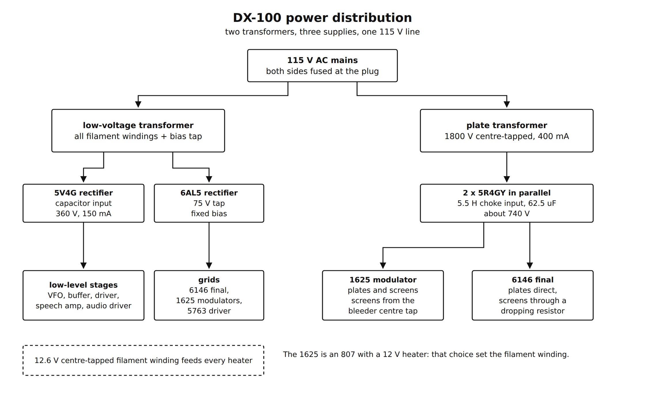
figs/make_diagrams.py, from the DX-100 assembly manual, https://archive.org/details/heathkittransmit00unse_0The low-voltage transformer carries every filament winding, including the 5-volt windings for the high-voltage rectifiers, and a tapped secondary for the bias rectifier. The 12.6-volt centre-tapped filament winding is grounded at its centre; six-volt valves are run from one side or the other so as to balance the load on the two halves, and the twelve-volt valves across the whole winding. A 5V4G with a capacitor-input filter gives 360 volts at 150 mA to the low-level radio-frequency and audio stages. A 6AL5, fed from the 75-volt tap with its own capacitor-input filter, gives the negative supply, and a resistance network divides it to set the correct fixed bias for the final, the modulators and the driver.
The high-voltage supply is the interesting one. Two 5R4GYs in parallel rectify an 1800-volt centre-tapped winding into a choke-input filter and two 125 µF, 450-volt electrolytics in series - 62.5 µF at 900 volts working. Heath explains the choice in the manual, and the explanation is a small lesson in supply design: conventional paper or oil capacitors of practical size let the voltage make “violent excursions as loads are suddenly applied or removed”, which on CW means chirp and on phone means poor peak power. Getting good dynamic regulation needs more capacitance than an oil capacitor can reasonably provide, so electrolytics become mandatory. A centre-tapped bleeder across the pair balances the two capacitors and doubles as the source of modulator screen voltage.
Both sides of the mains are fused in a special line plug, and every circuit entering or leaving the chassis passes through an LC harmonic filter.
2.7 What the layout is for: five-point TVI suppression
In 1955 a neighbour’s television set was the limiting factor on an amateur station, and Heath sold the DX-100 partly on what it did about that. The catalogue’s “5-point TVI suppression” is:
- pi-network interstage coupling, to reduce harmonic transfer from stage to stage;
- pi-network output coupling, to reduce harmonic radiation into the antenna;
- extensive shielding to isolate the RF stages and prevent intercoupling;
- filters on all incoming and outgoing circuits, to keep RF inside the cabinet;
- interlocking cabinet seams, so the cabinet itself does not leak.
Even the meter is behind a metal shield, to stop the hole in the panel radiating (1956 catalogue, p. 39). The chassis and sub-chassis are copper-plated for conductivity; the transformers are potted; the switch contacts in critical circuits are silver-plated or solid coin silver.

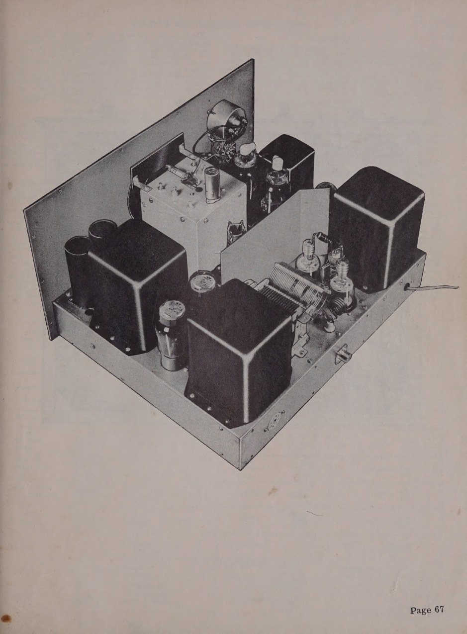
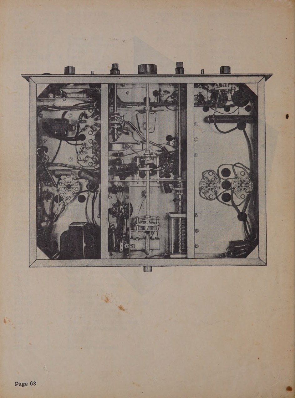
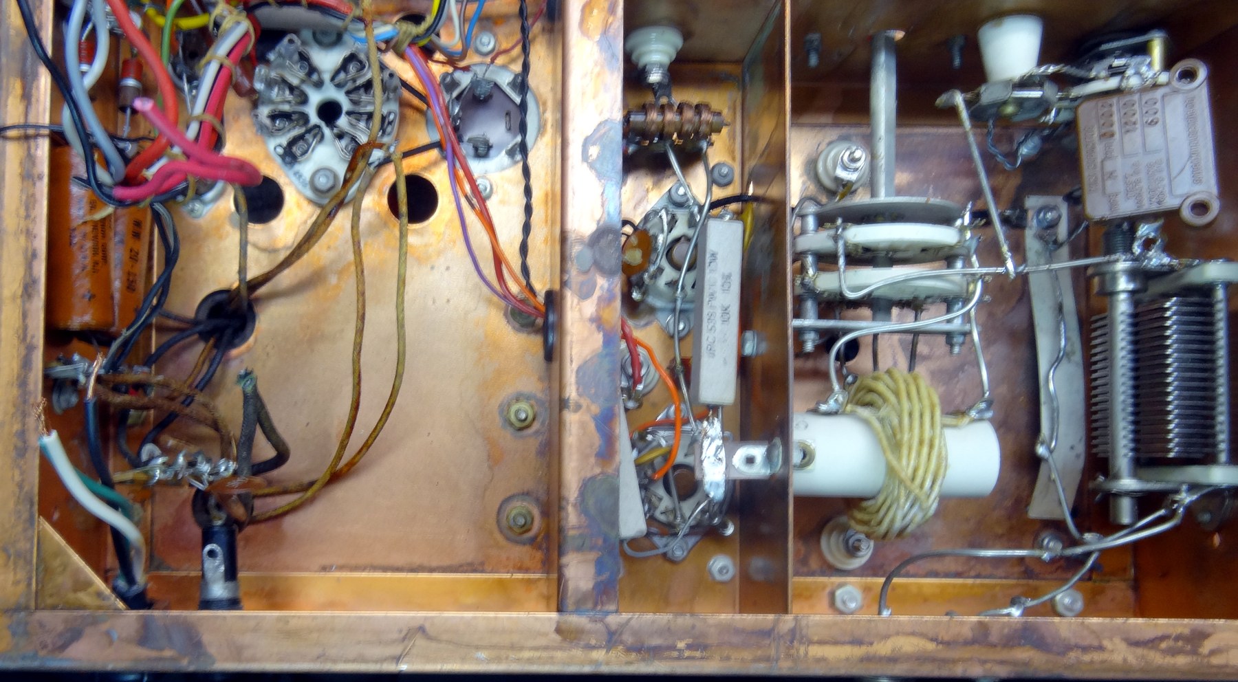
The DX-100B manual’s physical description spells out how the boxes serve the circuit: the chassis is 16-gauge steel, cadmium plated, sectionally framed so that the power, audio and RF circuits are isolated from each other and the frame itself stiffens the whole assembly. In the bottom view the low-voltage supply and audio are on the left, the low-power RF stages at centre front, the output pi network at centre rear, and the high-voltage supply on the right (DX-100B manual, p. 3).
2.8 Metering
One 0-1 mA movement with printed scales of 0-50 and 0-10 does all the work, switched to five points:
Table 2 — One 0-1 mA movement with printed scales of 0-50 and 0-10 does all the work, switched to five points
| Meter switch | Measures | Range |
|---|---|---|
| DRIVER | driver anode current | 0-50 mA |
| GRID | final grid current | 0-10 mA |
| PLATE | final anode current | 0-500 mA |
| VOLTS | final anode voltage | 0-1000 V |
| MOD. | modulator anode current | 0-500 mA |
With those five readings the operator can derive the anode input power directly, which is what the licence conditions of the day were written in terms of, and can watch the modulator current for evidence of modulation. The scales are not marked with the multipliers, so reading the meter is a small act of translation each time - the manual prints the table twice and tells the builder to study it before applying power (manual, p. 51).
2.9 The schematic
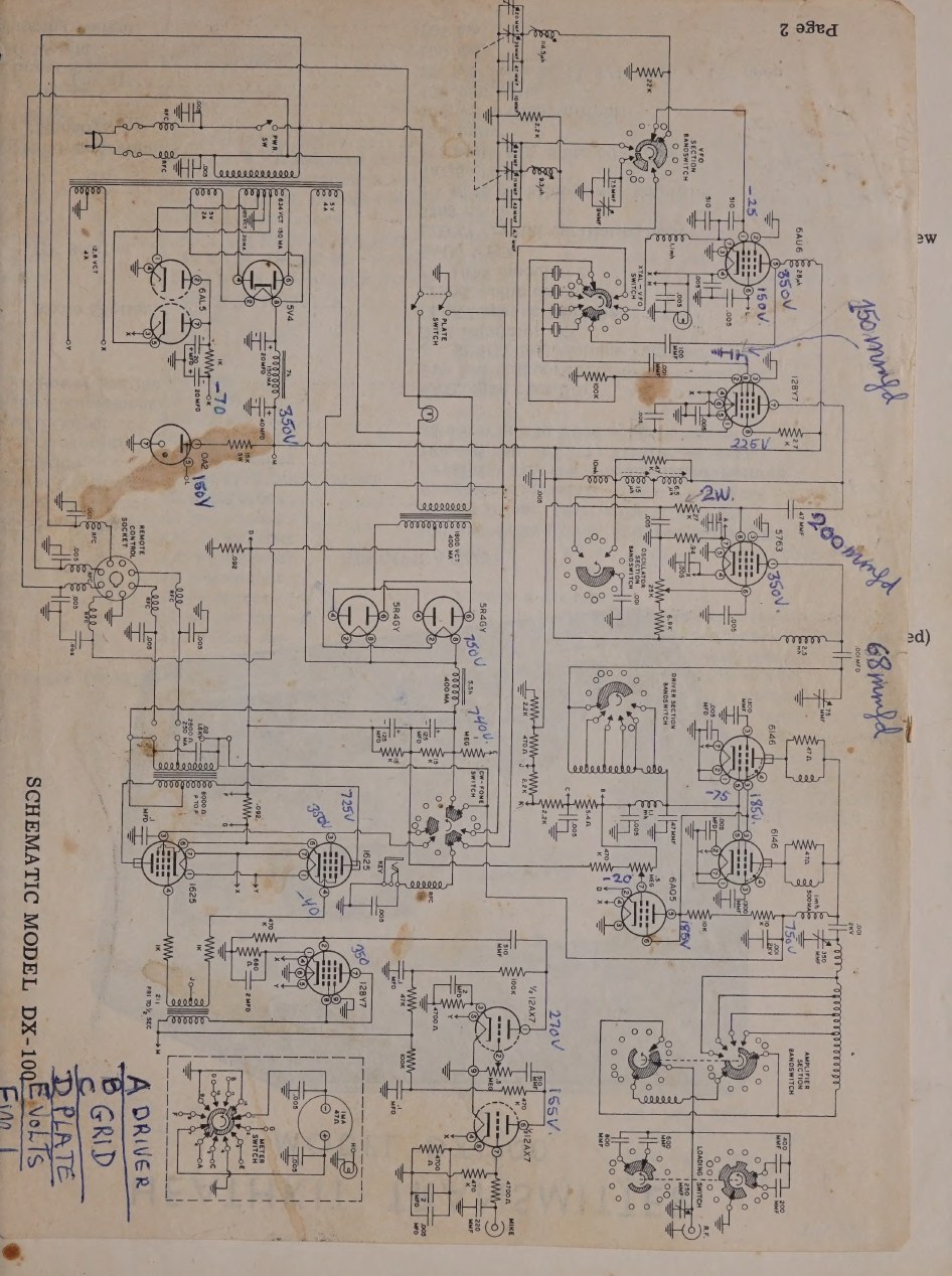
A separate schematic sheet and a schematic-plus-layout sheet also circulate as standalone scans, which are the most convenient things to print for bench work (schematic; schematic and layout).
Sources
- Assembling and Using Your Heathkit Transmitter Model DX-100, circuit description pp. 3-5, tuning instructions pp. 50-51, schematic sheet. DLARC scan, Internet Archive
- Assembly and Operation of the Heathkit Transmitter Model DX-100B, physical and electrical description p. 3. Internet Archive
- Heathkit DX-100 schematic, and schematic and layout sheets. Schematic · Schematic and layout
- Heathkit 1956 catalogue, pp. 38-39 (circuit summary and the five-point TVI list). World Radio History
- Bob Eckweiler, AF6C, “Heath DX-100 HF AM/CW Transmitter”, Heathkit of the Month #8. w6ze.org
- Mark Bell, K3MSB, DX-100B restoration pages. k3msb.com
Comments (0)