DX-100 Transmitter · Volume 4
Tuning and Use
A DX-100 is not switched on so much as brought up. Ten controls have to be set before power is applied, a clamp adjustment has to be made behind the panel, the driver and the final are tuned against the meter in a fixed order, and the loading is walked up in steps while the final is re-dipped after each one. None of this is unusual for a plate-modulated transmitter of the period; all of it has to be done in the right sequence, because the wrong sequence puts 740 volts across an untuned tank with full drive applied. This volume covers the panel, the tune-up, VFO calibration, getting on frequency, keying, the antenna, and the sideband conversion that turned an AM rig into an SSB one.
4.1 The panel
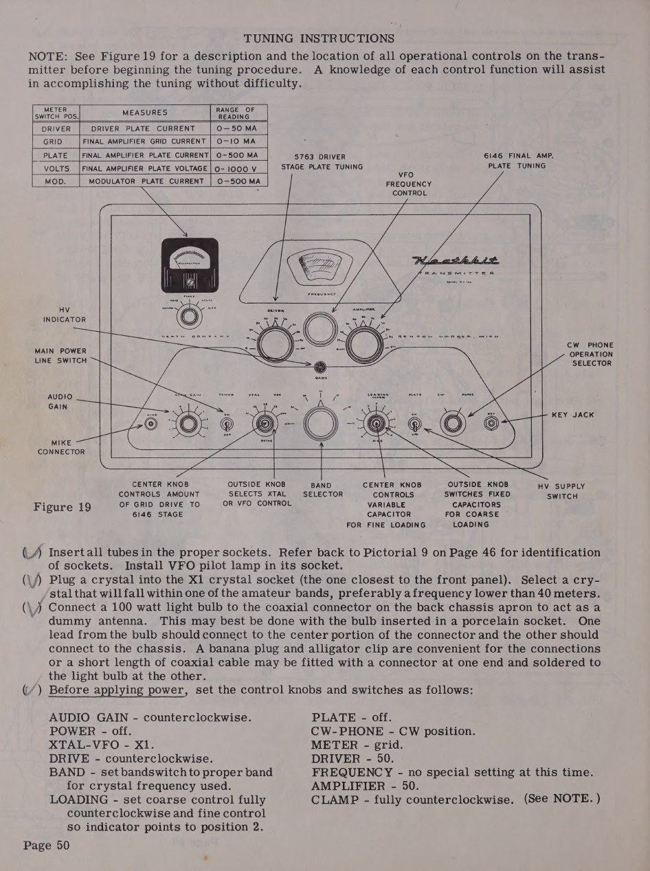
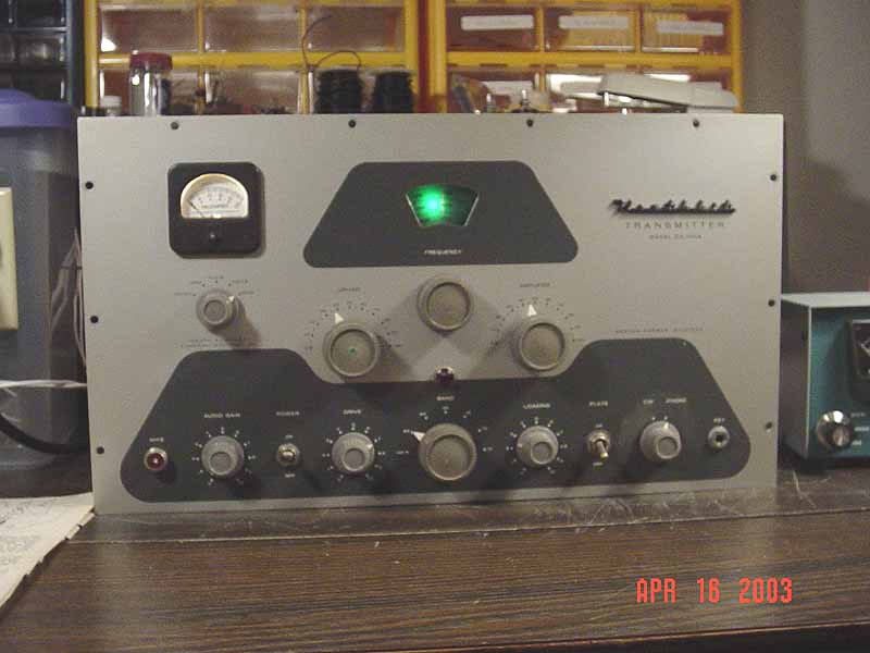
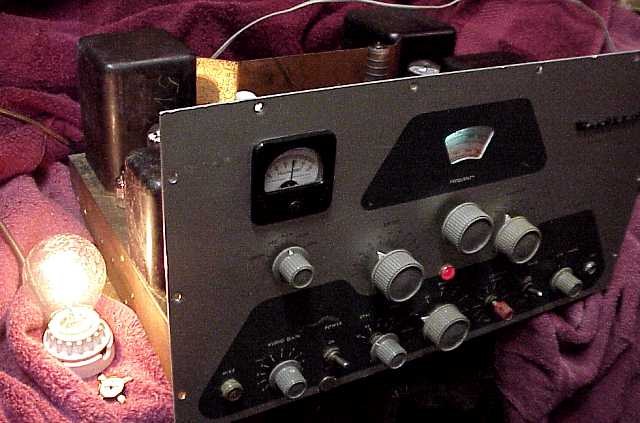
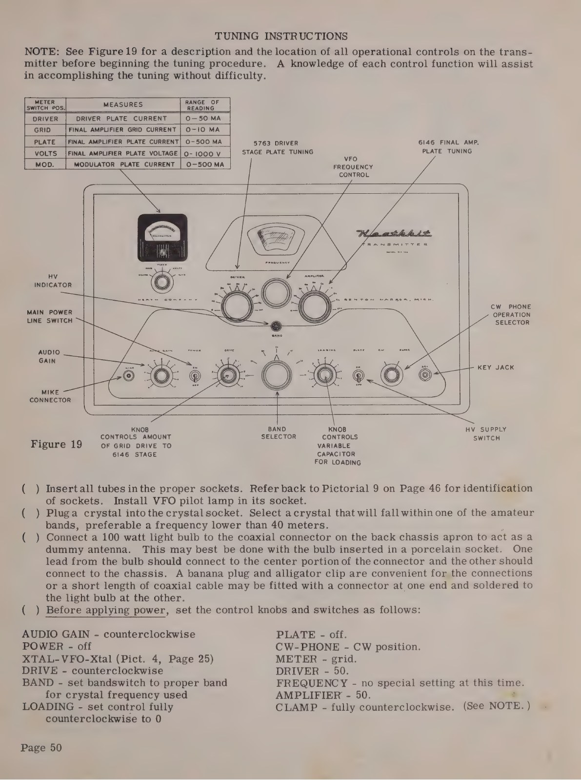
Reading from the top: the meter at the left, the illuminated VFO dial at the centre, the Heathkit nameplate at the right. Below the meter, the meter selector. Across the middle, three large knobs: DRIVER tuning, VFO FREQUENCY, and AMPLIFIER tuning, with the high-voltage indicator lamp under the dial. Along the bottom: microphone connector, AUDIO GAIN, the POWER switch, the dual-concentric XTAL-VFO switch with DRIVE at its centre, the BAND selector, the dual-concentric LOADING controls - coarse outside, fine inside - the PLATE switch, the CW-PHONE switch and the key jack.
On the DX-100B the crystal-VFO switch has gone inside the cabinet, under a hatch in the top, and the two loading controls have become one geared control. That is the quickest way to tell the two apart across a room.
4.2 Tune-up
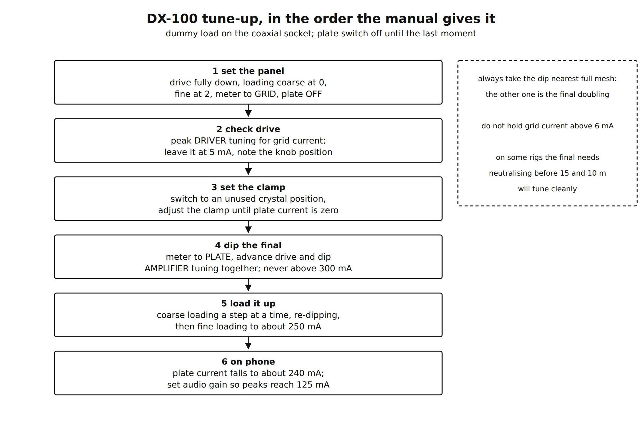
figs/make_diagrams.py, from the DX-100 assembly manual pp. 50-51, https://archive.org/details/heathkittransmit00unse_0The manual’s first tune-up is done into a dummy load, and its dummy load is a 100-watt light bulb in a porcelain socket wired to the coaxial connector - a perfectly serviceable resistive load at these powers, and one that shows the output as brightness. Before power:
- AUDIO GAIN fully counter-clockwise, POWER off, PLATE off;
- XTAL-VFO to X1, with a crystal in the socket nearest the panel;
- DRIVE fully counter-clockwise, BAND set to the crystal’s band;
- coarse LOADING fully counter-clockwise, fine LOADING at 2;
- METER to GRID, DRIVER at 50, AMPLIFIER at 50;
- the CLAMP screwdriver adjustment, behind the panel beside the VFO box, fully counter-clockwise.
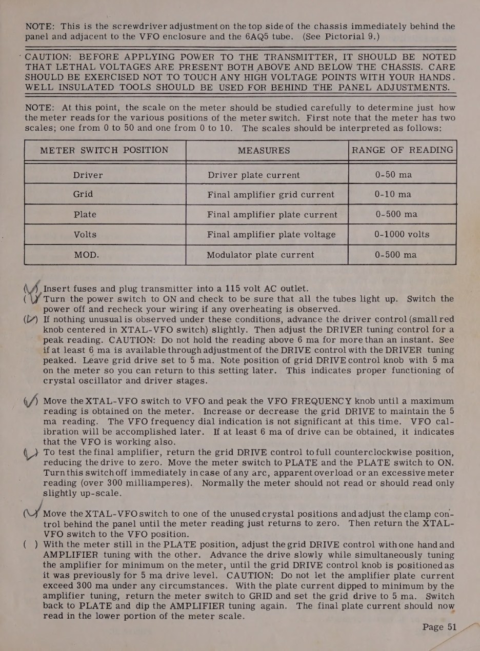
Then the sequence. Switch on and check that every valve lights. Advance DRIVE slightly and peak the DRIVER tuning for grid current, without holding the reading above 6 mA for more than an instant; settle at 5 mA and note where the knob sits. Switch to VFO and confirm that the same drive is available, which proves the oscillator. Return DRIVE to zero, meter to PLATE, PLATE switch on: the reading should be at or near zero, and anything over 300 mA or any sign of an arc means switch off at once. With the XTAL-VFO switch in an unused crystal position - that is, with no drive - set the clamp adjustment until the final’s anode current just returns to zero, and no further.
Now the part that has to be done with both hands: advance the drive with one and dip the AMPLIFIER tuning with the other, alternately, until the drive is back at the 5 mA setting and the anode current is dipped to minimum, never letting it exceed 300 mA. The manual adds a warning that catches new owners on the higher bands: on some bands two dips can be found, and the correct one is always the dip at the higher reading on the AMPLIFIER dial, with the capacitor plates nearer full mesh. The other dip is the final doubling.
Loading follows: one step of COARSE LOADING at a time, re-dipping after each step, until the meter reads about 200 mA, then FINE LOADING to bring it to a normal operating load of about 250 mA, re-checking that grid current is still 5 mA. On phone, the anode current falls to about 240 mA; with the meter in the MOD. position and the microphone connected, the audio gain is advanced until speech peaks reach about 125 mA, against an unmodulated reading of about 50 mA, and the dummy-load lamp visibly brightens on peaks.
Two numbers in that procedure deserve a note. The 250 mA loading point is a deliberate ceiling, not a maximum: the manual says plainly that the rig will often load higher, but that the pi network’s harmonic suppression is better if the output capacitor is not run down to minimum, and that the extra 10 or 15 watts “would not make any appreciable difference at the receiving end”. And 250 mA at about 740 volts is 185 watts of anode input. Restorers who work these rigs argue that the manual’s figures sit above the 6146’s intermittent-service rating for a pair in AM work, and run them lower for the sake of valve life (wireless-girl.com); the point is taken up in the restoration volume.
4.3 VFO calibration
Calibration is done against a frequency standard - the manual names the wartime LM and BC-221 heterodyne frequency meters and specifically warns against using an ordinary service signal generator - or, failing that, against as many band-edge crystals as the builder can borrow. Everything is allowed to warm up for half an hour first.
Each range has a trimmer capacitor that sets a point near the low end of the dial and a coil slug that sets the spread to the high end; the two interact, so they are adjusted alternately until both ends agree. Trimmer A and slug B serve 1750-2000 kc, trimmer C and slug D serve 7000-7425 kc, and trimmer E alone sets the 11-metre range at 27 mc. Two further slugs, F and G, peak the buffer’s anode coils: F is adjusted for maximum grid current with the bandswitch on 10 metres and the dial at 28.8 mc, G with the bandswitch on 15 metres and the dial at 21.3 mc (manual, pp. 52-53).
4.4 Getting on frequency
There is no spotting switch on the original DX-100, but there is a technique, and it is in the manual. On phone, with the PLATE switch off, move the CW-PHONE switch to CW: this energises the first three stages only, and enough signal reaches the station receiver to zero-beat the VFO against an incoming station. On CW, simply pressing the key with the PLATE switch off does the same. In either case, if the frequency has moved more than a few kilocycles the driver - and after the plate switch goes back on, the final - must be retuned.
The DX-100B gained nothing here, but the Apache that replaced it has a dedicated frequency-spotting push-button on the panel, and Heath’s own improved-keying modification for the DX-100 adds one.
4.5 Keying
The original keying is cathode keying of the VFO and the buffer together; the driver and final sit biased to cut-off and come to life when drive appears. Heath’s own later modification sheet is unusually frank about what that costs. Starting and stopping the VFO abruptly tends to produce chirp or frequency shift, worst on the higher bands, and because nothing shapes the keying waveform there can be key clicks as well (Improved Keying for the DX-100).
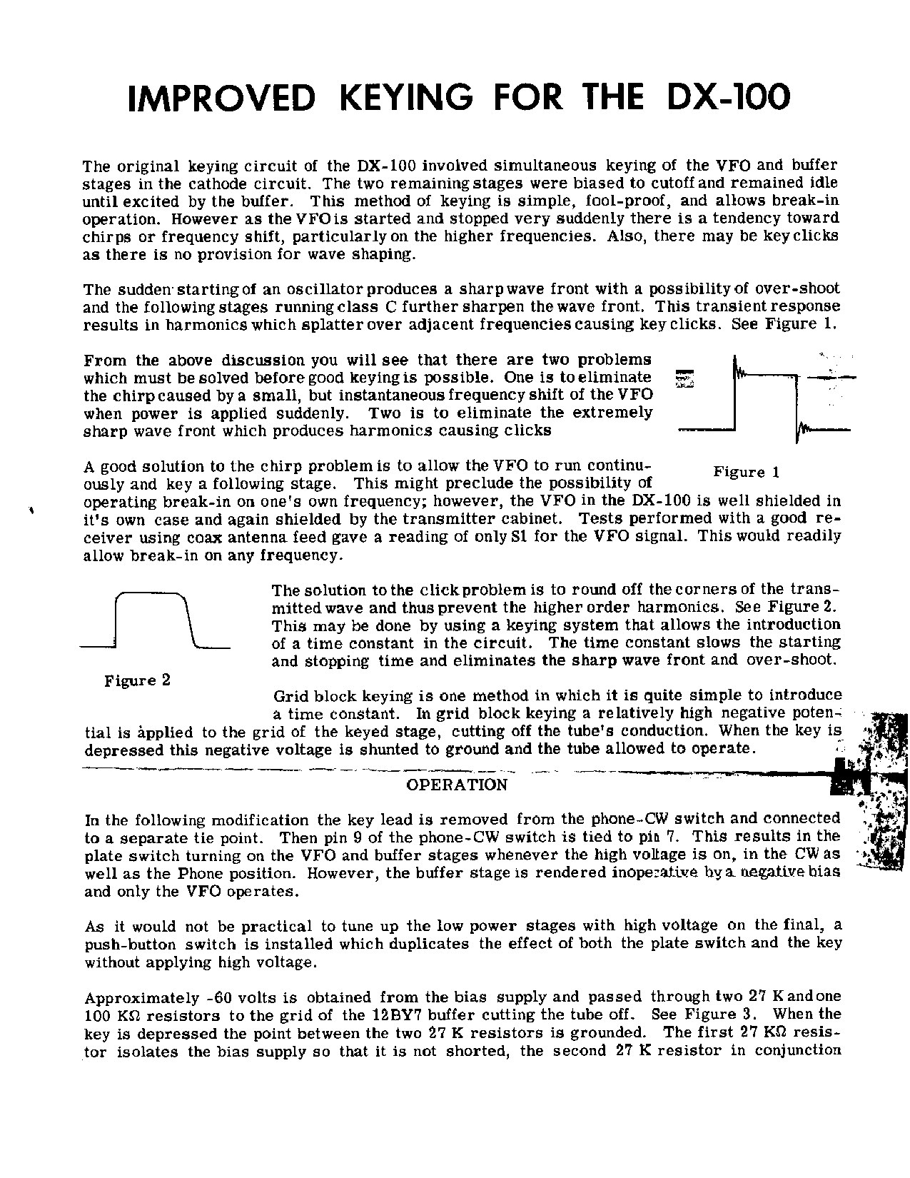
The fix Heath published has two halves. The chirp is cured by letting the VFO run continuously and keying the stage after it; the company defended this against the obvious objection - that a continuously running oscillator spoils break-in - by measuring it, reporting that with a good receiver on coaxial feed the VFO leakage read only S1 through its own shielding and the cabinet. The clicks are cured by grid-block keying the 12BY7 buffer: about -60 volts from the bias supply through a chain of two 27 kilohm resistors and a 100 kilohm resistor holds the valve cut off, the key grounds the point between the two 27 kilohm resistors, and a 0.15 µF capacitor charging and discharging through them shapes both the make and the break. Because the plate switch now turns on the VFO and buffer in the CW position as well as phone, a panel push-button is added that duplicates the effect of the plate switch and the key without applying high voltage - the spotting switch the rig had lacked. The sheet ends with the clamp re-adjustment the change requires, and with a sentence that Heath repeated whenever it published a modification: “This modification is strictly optional on the part of the builder.”
Two later observations are worth setting beside it. The grid-block conversion leaves a small backwave, because stray capacitance couples a trace of the running VFO through the cut-off buffer; and if the rig is later fitted with the SB-10 sideband adapter, Heath’s own SB-10 manual recommends returning to cathode keying, or adding a switch section that grounds the VFO and buffer cathode return only while transmitting, since on SSB the plate switch is on continuously and the free-running VFO becomes a nuisance during standby (SB-10 manual, p. 51; wireless-girl.com DX-100 notes).
4.6 Antennas, and the low-pass filter
The pi network will match non-reactive loads from about 50 to 600 ohms, which covers most unbalanced lines and end-fed wires. Balanced systems - folded dipoles, Zepps - need an antenna coupler or balun so that neither leg sits at ground potential, since one side of the transmitter output is grounded. Heath sold the AC-1 antenna coupler and, by 1958, the B-1 balun coil kit at $8.95 for exactly this (1958 catalogue, p. 49).
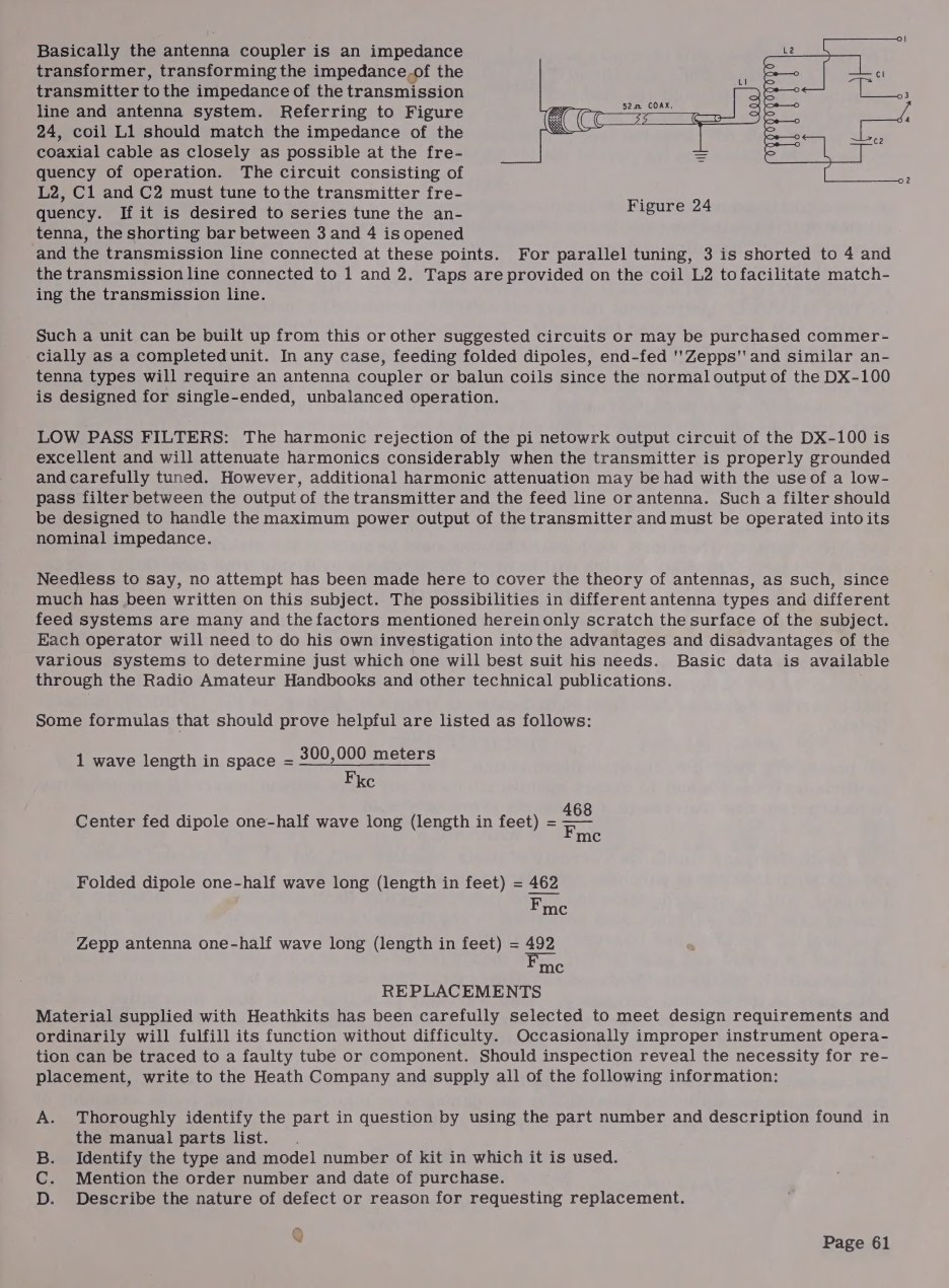
On television interference the manual is confident about the pi network and then, in the next breath, tells the owner to fit a low-pass filter anyway: harmonic rejection is called “excellent” in a transmitter that is properly grounded and carefully tuned, and the same page then recommends a low-pass filter between the transmitter output and the feed line for further attenuation. The filter must be rated for the transmitter’s full output and operated into its nominal impedance (manual, p. 61).
4.7 The remote socket
The octal socket on the rear apron is more useful than its one line in the catalogue suggests. It duplicates the plate switch for external control (pins 3 and 4, with pins 1 and 8 completing the circuit for phone operation, so a double-pole switch or relay is required); it provides 110 volts between pins 2 and 4 whenever the plate switch is on, for an antenna changeover or receiver muting relay; pin 8 is an auxiliary ground for shielded control cable; and, after clipping two jumpers on terminal strip FF and adding two more, it brings out up to 80 watts of audio at 500 ohms between pins 6 and 7. That last modification turns the DX-100 into the driver for a larger plate modulator - the intended path for an owner going to a kilowatt (manual, pp. 58-59).
Heath’s VX-1 electronic voice control, in the catalogue by 1958, was designed around exactly this socket: it switches the station from receive to transmit on voice, mutes the receiver and operates the antenna relay, and the catalogue copy says it was “designed primarily for operation with the DX-100 Transmitter” (1958 catalogue).
4.8 Single sideband: the SB-10 and the MK-1 kit
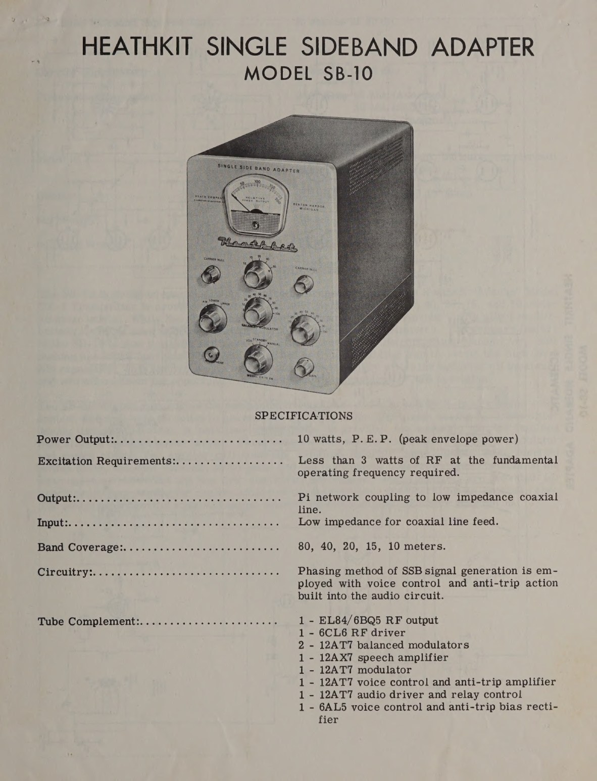
The SB-10 SSB Adapter of 1959 generates a 10-watt peak-envelope-power single-sideband signal by the phasing method, on 80 through 10 metres, and feeds it into the transmitter’s final amplifier for amplification, with voice control and anti-trip built in. It cost $89.95 - about half the price of the transmitter it modernised (1959 catalogue, p. 45).
Fitting it to a DX-100 or DX-100B means three changes, set out in the SB-10 manual. The radio-frequency path between the 5763 driver and the 6146 grids is broken and brought out to two coaxial connectors on the rear apron, so that the adapter can be inserted between them - with a coaxial jumper of RG-62/U restoring the normal path for AM and CW. The final is put into class AB1 for linear operation, its screen voltage regulated at 210 volts by two OB2s in series and the fixed bias adjusted, via a new 3 kilohm control replacing a 2.2 kilohm resistor in the bias string, to give 50 to 55 mA of resting anode current. And provision is made to lift the ground end of the bias string during standby so that the final can be cut off without switching the plate transformer primary on and off (SB-10 manual, pp. 50-51).
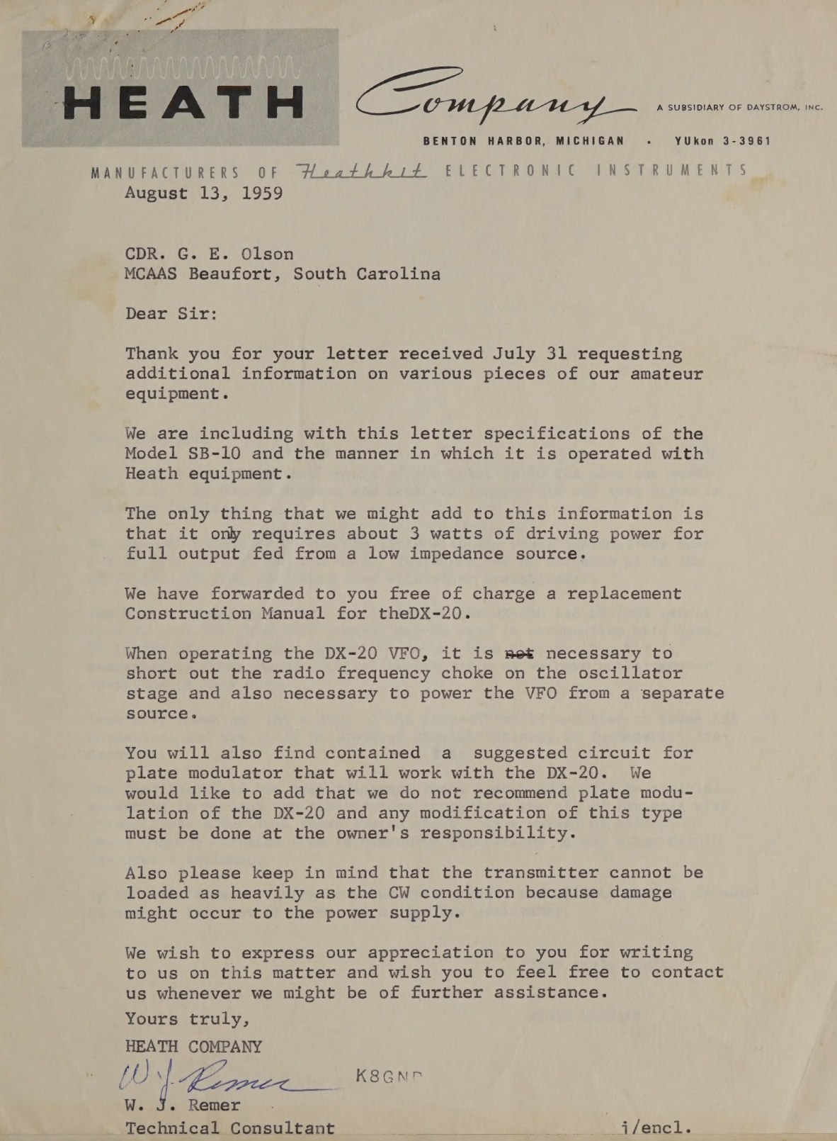
On the DX-100B the chassis is already punched for the connectors; on the original DX-100 the owner drills it. Heath sold the parts as a single kit for either model, and a 1959 letter from the factory names it: the kit that adapts either transmitter for use with the sideband adapter is “the MK-1”. The same letter, signed by a technical consultant at Benton Harbor, sets out company policy on fitting the adapter to other makers’ transmitters: “As a matter of policy, Heath Company refrains from recommending alterations to any other manufacturer’s equipment” (SB-10 manual, correspondence pages).
Whether the conversion was worth doing is a separate question. The DX-100’s VFO was designed for AM and CW, where a drift of a few hundred cycles is invisible; on sideband the same drift is audible as a slow change of pitch. Restorers who have tried it generally advise against, on the grounds that the oscillator “is barely adequate in stability for AM and CW, not good enough for SSB operation” (wireless-girl.com). Heath evidently reached a similar conclusion: the Apache that replaced the DX-100B has a completely redesigned VFO, described in the 1959 catalogue as providing “low drift frequency control necessary for SSB transmission”.
4.9 On the air
The operating characteristics that users report have been consistent for seventy years. The audio is punchy rather than wide, by design: 300 to 3000 cycles, with deliberate high-level clipping to raise the average modulation, and a modulation transformer built out as a low-pass filter to keep the clipping from splattering. Eckweiler, comparing it with the screen-modulated DX-40 he had been using, recalled that “the DX-100 ran cleanly and the quality of my audio reports were excellent”, and that the extra sideband power made contacts easier to hold when the band was poor (Heathkit of the Month #8).
The rig runs hot. 600 watts in at the wall on phone, most of it leaving as heat from a cabinet with modest perforation, means the case wants clear air above it; restorers advise a fan and nothing stacked on top. And the transmitter should be tuned quickly: the manual’s cautions about holding grid current above 6 mA or anode current above 300 mA for more than an instant exist because the 6146 screens and the clamp arrangement have very little margin while the tank is off resonance.
Sources
- Assembling and Using Your Heathkit Transmitter Model DX-100: tuning instructions pp. 50-51, calibration pp. 52-53, in case of difficulty p. 55, remote socket and antennas pp. 58-61. DLARC scan, Internet Archive
- Improved Keying for the DX-100, Heath Company modification sheet. Internet Archive
- Heathkit Single Sideband Adapter Model SB-10 manual, including the DX-100/DX-100B modification and the bound-in Heath correspondence of August 1959. DLARC scan · second scan
- Assembly and Operation of the Heathkit Transmitter Model DX-100B, tuning instructions p. 50. Internet Archive
- Heathkit 1958 catalogue (VX-1 voice control, B-1 balun) and 1959 catalogue (SB-10, Apache VFO). 1958 · 1959
- Bob Eckweiler, AF6C, Heathkit of the Month #8. w6ze.org
- wireless-girl.com, Heathkit DX-100 restoration and modification notes. wireless-girl.com
- Bob Post, “Heathkit DX-100 transmitter lives again!”, boatanchorpix. boatanchorpix.x10host.com
Comments (0)