DX-100 Transmitter · Volume 5
Restoration and Common Faults
A DX-100 that has sat in a garage since 1972 is not a radio; it is a box of 1950s capacitors wired to a supply that can kill. Everything about restoring one follows from that. The high-voltage filter is 62.5 µF charged to something like 740 volts in normal operation - one restorer warns that it can approach 900 volts (wa3dsp.org) - the bleeder is the only thing that discharges it, and the original line cord has no safety earth. The manual itself tells the owner to short from the chassis to the hot end of the bleeder and to each filter capacitor with a screwdriver blade before making resistance measurements, and that instruction is as good today as it was in 1955. Work with one hand where possible, unplug rather than switch off, and treat every electrolytic as charged until it has been shorted.
5.1 Before power: the survey
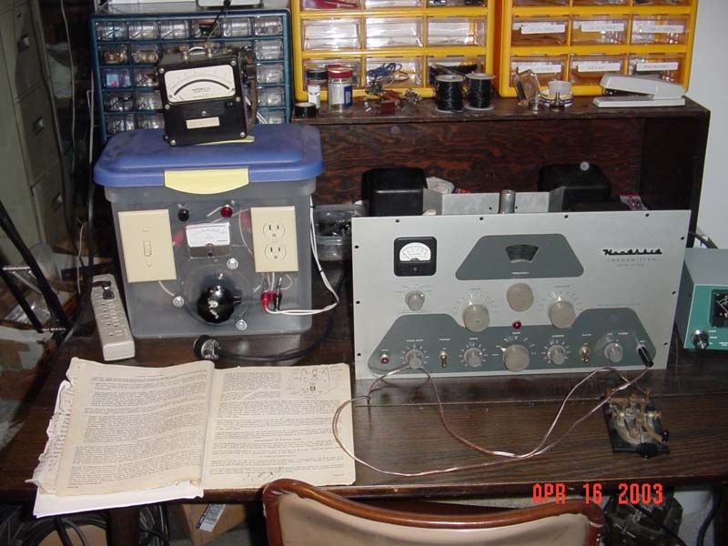
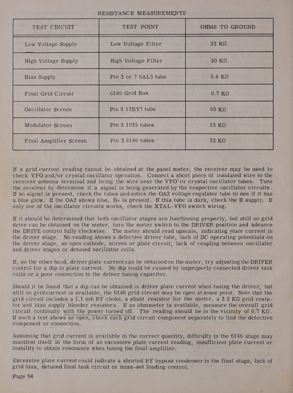
The order that most restorers follow is the same. Clean the chassis and vacuum out sixty years of dust and mouse debris. Check the line cord and its plug - the original fuses both sides of the mains in a special plug, and any rig that reaches a modern bench should be converted to a three-wire earthed cord with a fuse on the chassis, which is the single most valuable change that can be made to one of these transmitters. Pull the rectifiers. Do the manual’s own resistance checks on the low- and high-voltage supplies with the plug out: the manual prints two charts for exactly this, one to work through if a fuse blows with the POWER switch, the other if it blows with the PLATE switch.
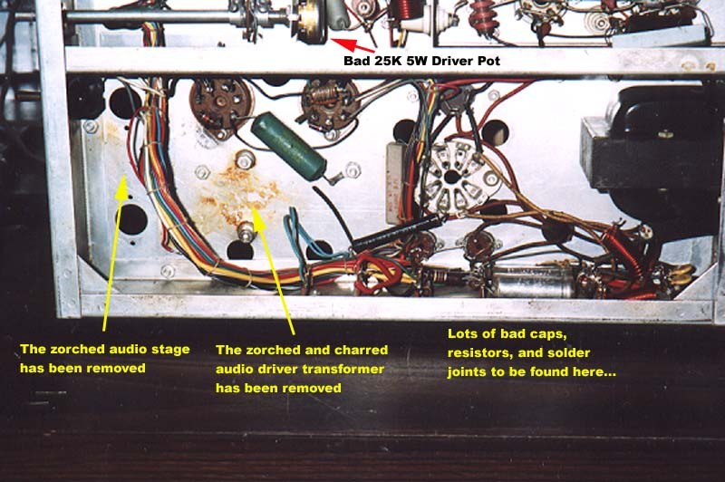
Then look for what the last owner did. Restorers report finding the original builder’s errors still in place decades later - “poorly soldered connections” and wiring mistakes at Doug Roth WA3DSP’s bench, “lots of bad caps, resistors, and solder joints” at Mark Bell K3MSB’s - along with previous modifications, some of them sensible. One DX-100 arrived at Bob Post’s bench with a 100-ohm resistor in the primary circuit on a three-position toggle, added by an earlier owner to limit power during tune-up; he judged it worth keeping.
5.2 The known failure modes
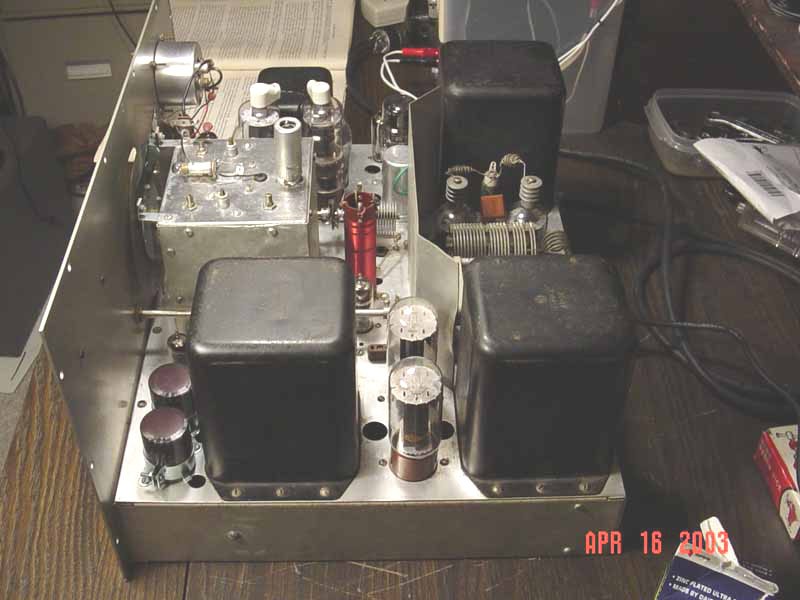
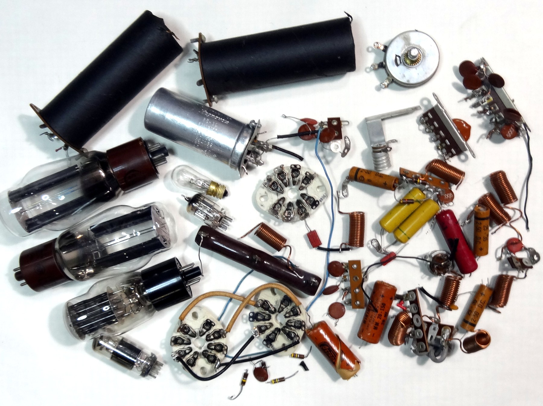
Electrolytic capacitors. All of them are suspect and most are past saving. The parts list accounts for them exactly: two 125 µF 450-volt units, which are the high-voltage filter in series; one 20-20-20 µF 450-volt can; two 20 µF 150-volt units; and three 2 µF 50-volt units (parts list, p. 64). Either reform them slowly on a variac or bench supply and accept that they may not hold, or replace them. Re-capping kits for the DX-100 and DX-100B are sold ready-made, which spares the restorer the job of working out voltage ratings and can sizes (Hayseed Hamfest DX-100 re-cap kit).
The loading capacitor assembly. This is the DX-100’s signature fault. Coarse loading is done by switching four fixed mica capacitors - 200, 400, 600 and 800 pF - in combination, and those “postage stamp” micas and their wiring sit in a high-current, high-voltage part of the tank circuit. They short, and they run hot. Bob Post found “two sections of the octagonal… loading capacitor SHORTED” and replaced them with three transmitting micas. In CQ for October 1956, Lloyd Jones W6DOB reported that he could not properly load a 50-ohm line on 20, 15 and 10 metres and that “the small mica condenser and associated wiring ran extremely hot”, which he attributed to the assembly being near self-resonance at those frequencies; he removed the fixed micas and the 250 pF fine-loading variable and fitted a three-gang broadcast variable of about 1200 pF maximum in their place, coupled to the fine-loading shaft, leaving the coarse switch in place but unused. Heath came to the same conclusion by a different route: the DX-100B replaced the stepped arrangement with a single larger geared variable “less prone to arcing”, and, as Chuck Penson records, a modification kit was offered to DX-100 owners to bring them up to the same standard (boatanchorpix; W6DOB’s article as quoted in a 2003 boatanchors list posting scanned into this manual copy).
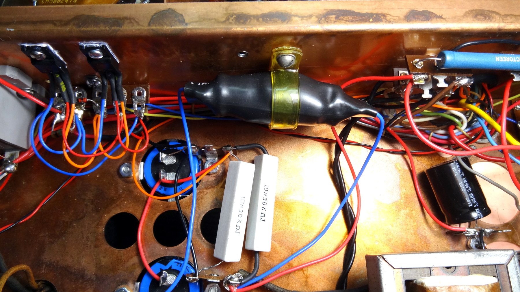
The drive potentiometer. The 25 kilohm wirewound control that sets the 5763’s screen voltage fails, and replacements in the right rating are not easy to find; Mark Bell found one that had dropped to about 17 kilohms, which showed up as a low-voltage supply reading 30 per cent out of tolerance during the manual’s resistance checks. The AM Press/Exchange for May 1989 carried a substitute circuit by Norm WB2SYQ that drives the screen through a television horizontal-output transistor from a 1 megohm pot, which is still the commonly cited fix (Nostalgic Kits Central, DX-100 modifications; k3msb.com).
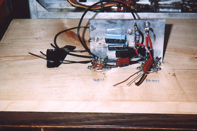
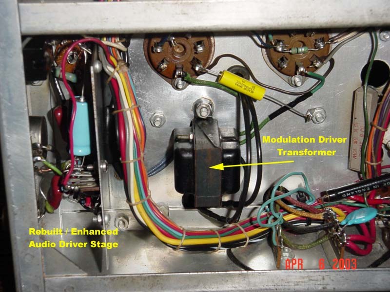
Charring under the audio driver transformer. The driver transformer and the chassis beneath it are a recurring casualty; in one DX-100B the chassis under it was “charred and zorched”, the transformer’s leads came away in the restorer’s hands, and there were burn marks beside each of the rectifier sockets. The remedy that worked was to build a complete replacement audio sub-assembly on the bench - new sockets, new shield, correct spacing measured from the original - and then fit it.
The mode switch. The ceramic CW-phone switch is fragile and hard to find. One found cracked in two was repaired with slow-setting JB Weld plus wire lacing through the adjacent holes and a covering of epoxy, and worked afterwards.
VFO drift. Every account agrees that the oscillator drifts more than its designers hoped, and the reasons are cumulative: heat from a 600-watt transmitter in a lightly ventilated cabinet; a 6AU6 run at more anode voltage than it needs; ceramic switch wafers and shaft bearings that shift with age; mica capacitors that have aged. Doug Roth’s approach was to attack the heat and the voltage rather than the mechanics - a 6AH6 in place of the 6AU6, a solid-state regulator dropping the oscillator anode voltage to about 160 volts, an OB2 in place of the OA2 to bring the screen to 105 volts, a larger anode choke, every joint in the compartment resoldered, and the pilot lamps changed to LEDs so they stop heating the box. He reports drift “on the order of a hundred cycles or less” after warm-up. Others replace the 500 pF mica capacitors in the frequency-determining circuit with polystyrene types, or give up and drive the rig from an external synthesised source, keeping the 12BY7 buffer (wa3dsp.org; wireless-girl.com).
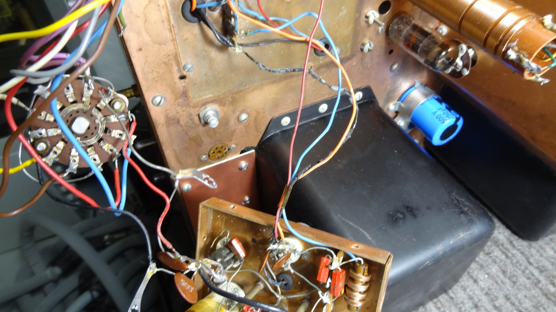
Overvoltage in the modulator. The 1625 screens are fed from the centre tap of the high-voltage bleeder, which is not a regulated point, and restorers measuring them find them well above the valve’s rating - around 400 volts against a nominal 250 in one worked case. Regulating that supply is one of the changes that pays for itself in valve life.
Rectifier sockets and arcing. The 5R4GY sockets sit at high voltage with their pins close together; ageing and dirt lead to flashover. Cleaning, increasing the insulation, or replacing the sockets is routine.
Small parts. Missing aluminium heat-dissipating anode caps, missing fuses, cracked or wrong knobs, frozen dual-concentric controls, a leaky 0.02 µF high-voltage capacitor across the modulation transformer secondary, and the inevitable carbon resistors that have drifted high. Valves themselves are usually the least of the problem; the 6146, 1625, 12BY7, 12AX7, 6AU6, 5763 and 6AQ5 are all still obtainable, and the rectifiers can be replaced with solid-state equivalents if the consequences are understood.
5.3 Bringing it up
One published bring-up records the mains current at each stage of the process, which is a useful sanity check for anyone doing it for the first time: with no valves fitted, 230 mA with the plate switch off; with the rectifiers and regulator in, 420 mA off and 1.2 A on; with the audio valves added, 770 mA off and 2.25 A on AM; and with the 6146s in and the rig running, about 5 A on CW and 5.2 A on AM (k3msb.com).
With the rectifiers out, the wiring checked and the obvious casualties replaced, the usual sequence is: heaters only at reduced mains voltage, checking that filament voltages are right and nothing smokes; electrolytics reformed on an external supply, or replaced; low-voltage rectifier back in and the 360-volt line checked; then the high-voltage supply, brought up on a variac with the meter on VOLTS and a hand near the switch. A series lamp - the “dim bulb” - in the mains lead is standard practice for the first power-ups and will limit the damage if a shorted capacitor has been missed.
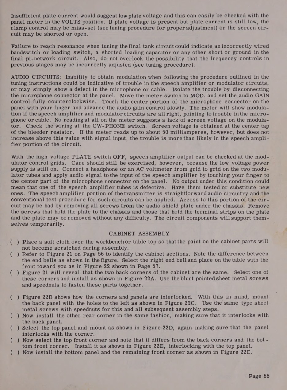
The manual’s own fault-finding section is still the best starting point for a rig that powers up but will not work, because it is written around the tune-up procedure: localise the trouble to a stage, then use the block diagram and the meter. Its specific hints remain useful - shorts between adjacent pins on miniature sockets, joints that look soldered but have a film of rosin between wire and terminal, and the use of the station receiver with a short wire near the VFO or crystal oscillator valve to prove that an oscillator is oscillating at all.
5.4 Modern substitutions, and their consequences
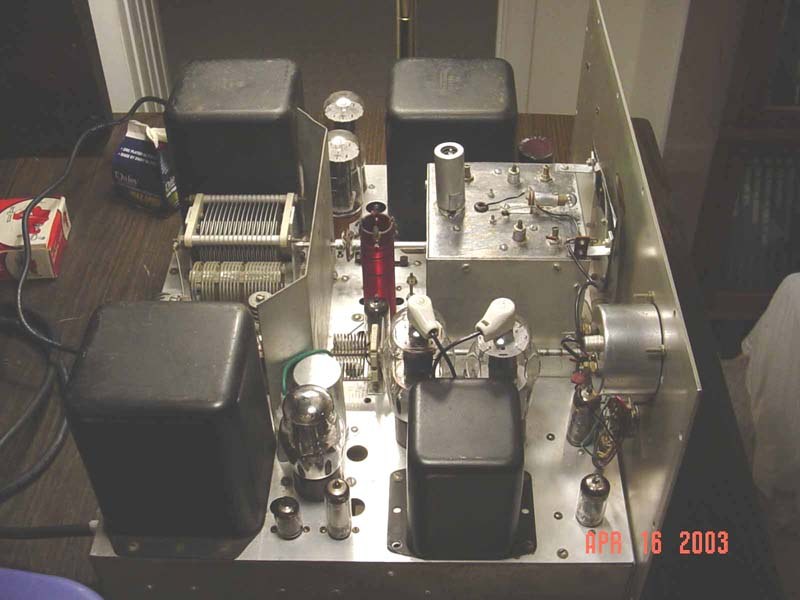
Solid-state rectifiers. Replacing the 5R4GYs and the 5V4G with silicon removes the rectifiers’ forward drop and raises every voltage in the rig, and it removes the slow warm-up that let the filter capacitors charge gently. Restorers who do it compensate: Doug Roth converted the low-voltage supply to choke input to hold the voltage down, used series strings of diodes for the high-voltage supply, and added a bleeder sized for the new conditions. Doing it without compensation is how a restored DX-100 ends up running its screens and modulators above rating.
6146B finals. Later-production 6146Bs are commonly fitted and are usually reported as an improvement in linearity and power handling. They are not electrically identical to the original 6146, and any change of final valve is a reason to check neutralisation and watch for parasitics rather than assume.
807s for 1625s. The 1625 is an 807 with a 12.6-volt heater. Where 1625s are scarce, 807s can be substituted by rewiring the sockets, and one restorer notes an incidental benefit: wiring the two 6.3-volt heaters in series across the existing 12.6-volt winding means that a failed heater takes both valves dark, rather than letting the rig limp on one modulator unnoticed.
LED pilot lamps. Cool, and in the VFO compartment that is a real gain rather than a cosmetic one.
5.5 Period and modern modifications
Table 1 — Period and modern modifications
| Modification | Source | What it does |
|---|---|---|
| Improved keying | Heath Company modification sheet | Grid-block keys the 12BY7 buffer with a shaping time constant and lets the VFO free-run; adds a panel spotting push-button |
| Loading capacitor rework | Lloyd Jones W6DOB, CQ, October 1956, pp. 34-35 | Replaces the stepped micas and fine variable with a three-gang broadcast variable; cures overheating and the inability to load 50 ohms on the high bands |
| Neutralisation of the final | W6DOB, same article | A short bare wire from the unused capacitor lug near the RF choke; makes 15 and 10 metres tune cleanly. Not every rig needs it |
| Loading modification kit | Heath Company, per Chuck Penson | Factory kit bringing the DX-100’s loading arrangement up to the DX-100B’s geared variable |
| SB-10 conversion, MK-1 kit | Heath Company, 1959 | Class AB1 linear operation with the SB-10 sideband adapter (see the tuning volume) |
| Screen supply, 60/40 | Dean, The AM Press/Exchange, May 1989 | Derives the 6146 screen voltage 60 per cent from the modulated supply and 40 per cent from the unmodulated one, and raises the drive, to clean up modulation linearity |
| Screen RC phase correction | Dean, same issue | A capacitor across the screen dropping resistor to remove the phase shift between plate and screen modulation at the top of the audio range |
| Drive pot replacement | Norm WB2SYQ, same issue | A transistor circuit with a 1 megohm control, in place of the unobtainable 25 K 5 W pot |
| Audio enhancement | Tim Smith WA1HLR; Ed Santavicca AA8TV; Jim Lockwood K4CCF, “DX-100 Audio, Revisited” - all circulated through the AM Window | Widens and cleans up the speech chain, which was deliberately narrow and clipped as built |
| Solid-state overhaul | Doug Roth WA3DSP | Silicon rectifiers with choke input, regulated screens and bias, MOSFET keying and receiver muting, PTT relay control |
The modification literature is worth reading as a whole rather than shopping from. Two of its recurring themes are that the DX-100’s real linearity problem is in the final’s screen circuit rather than in the audio chain, and that the fixes which matter - the loading capacitor, the screen supply, neutralisation, a safety earth - are the ones that address a specific measured defect. The advice against two popular modifications is just as consistent: the SB-10 conversion asks more stability of the VFO than it has, and at least one restorer reports that the time-sequence keying scheme published in QST in 1956 makes drift worse on 40 metres and above (wireless-girl.com; Nostalgic Kits Central).
5.6 Living with a restored one
Run it cooler than the manual says. Heath’s tune-up loads the final to 250 mA at about 740 volts, and a restorer who wants his 6146s to last will calculate a target current from the measured anode voltage and the input he actually wants, allowing 15 to 20 mA for screen current because the meter reads cathode current rather than anode current alone. Fit a fan, and never stand anything on top of the cabinet: the perforations in the top are the air path for the final and the modulators.
Check the neutralisation, or at least check for it, before blaming the tank circuit for a rough note on 15 and 10 metres. Keep a low-pass filter in the feedline, as the manual asked in 1955 - modern receivers and modern neighbours are no more tolerant than 1955’s. And keep the manual open: a rig this old is as likely to be suffering from its last owner’s modifications as from its own age, and the schematic is the only way to know which.
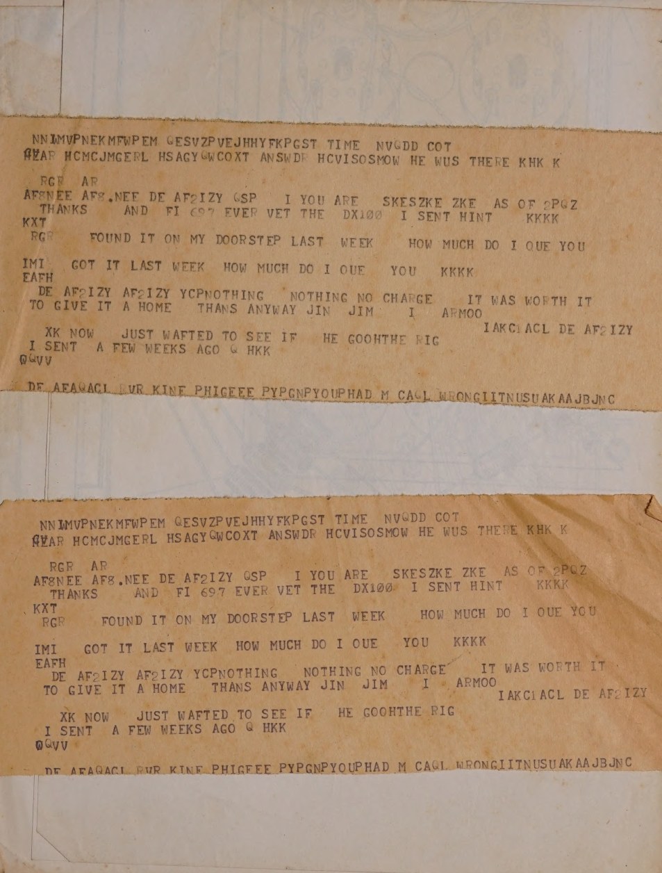
Bound into one of the scanned manuals is a strip of teleprinter paper, printed twice, that has nothing to do with Heath and everything to do with how these transmitters survive. It is a fragment of an amateur radio-teletype exchange. One operator says he found the DX-100 on his doorstep last week and asks how much he owes; the answer comes back “NOTHING NO CHARGE IT WAS WORTH IT TO GIVE IT A HOME”.
5.7 Safety, stated plainly
- The high-voltage supply reaches roughly 740 volts under load, and is warned to approach 900 volts lightly loaded, across 62.5 µF of electrolytic capacitance. That is lethal, and it remains lethal after the rig is switched off if the bleeder has failed.
- Discharge the filter capacitors deliberately, with an insulated tool, every time the chassis is opened - the manual says to short from the chassis to the hot end of the bleeder and to each capacitor.
- The original mains arrangement fuses both sides of the line and has no safety earth. Fit a three-wire earthed cord and a chassis fuse.
- Testing happens with the transmitter out of its cabinet: “REMEMBER VOLTAGES DANGEROUS TO LIFE ARE PRESENT AT PRACTICALLY ALL POINTS ON THE CHASSIS.”
- The rig weighs 100 pounds. Two people, or a bench at the right height, or a back injury.
Sources
- Assembling and Using Your Heathkit Transmitter Model DX-100: in case of difficulty and resistance charts, pp. 53-55; assembly warnings, p. 6. DLARC scan, Internet Archive
- A second scan of the DX-100 manual, with a 2003 boatanchors list posting bound in quoting Lloyd Jones W6DOB, CQ, October 1956, pp. 34-35, and Chuck Penson on the factory loading modification. DLARC, Internet Archive
- Doug Roth, WA3DSP, “Heathkit DX-100 Restoration”. wa3dsp.org
- Mark Bell, K3MSB, DX-100B restoration pages. k3msb.com
- Bob Post, “Heathkit DX-100 transmitter lives again!”, boatanchorpix. boatanchorpix.x10host.com
- wireless-girl.com, Heathkit DX-100 restoration and modification notes. wireless-girl.com
- Nostalgic Kits Central, DX-100 modifications, abstracting The AM Press/Exchange, May 1989. nostalgickitscentral.com
- Hayseed Hamfest, DX-100 re-cap kit. hayseedhamfest.com
- Heath Company, Improved Keying for the DX-100. Internet Archive
Comments (0)