DX-100 Transmitter · Volume 3
Building the Kit
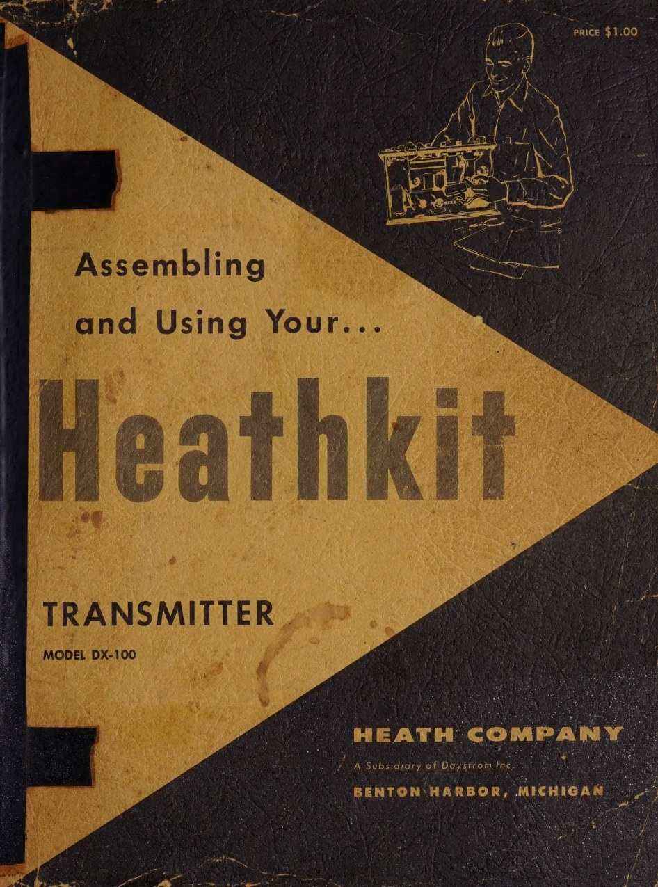
Everything that made the DX-100 formidable on the air made it formidable on the kitchen table. Sixty pounds of iron had to be mounted on a chassis the builder assembled; several hundred components had to be soldered into a rig in which lead dress matters; a cabinet arrived as a stack of flat panels; and at the end of it a first-time builder had to bring up a supply capable of killing him. Heath’s answer was the manual. The DX-100’s is a 68-page book with ten fold-in pictorials, and its organising idea is stated on page 6: the transmitter is built as a series of sub-assemblies. The manual calls this the “unit method of construction”, and gives two reasons for it — one large job becomes several small ones, and the weight and bulk of a big transmitter are postponed until the build is nearly finished (DX-100 manual, p. 6).
3.1 What arrived
The kit came by motor freight in a carton whose contents the manual expected the builder to check against the parts list before touching a tool: “UNPACK THE KIT CAREFULLY AND CHECK EACH PART AGAINST THE PARTS LIST. In so doing, you will become acquainted with each part.” The instruction that follows is one of the small honesty notes that run through Heath’s manuals: “Hardware items are counted by weight and if a few are missing, please obtain them locally if at all possible.”
Coils came pre-wound, the cable came pre-harnessed, and the transformers were potted - all three points made in the catalogue copy, because all three were selling points against a magazine construction article. The valves, cabinet and hardware were included; crystals were not.
3.2 How the manual is built
The structure is the same one Heath used across its line, at a scale to match the kit:
- an introduction and a full circuit description, before any assembly, with the block diagram;
- notes on assembly and wiring, including the soldering rules;
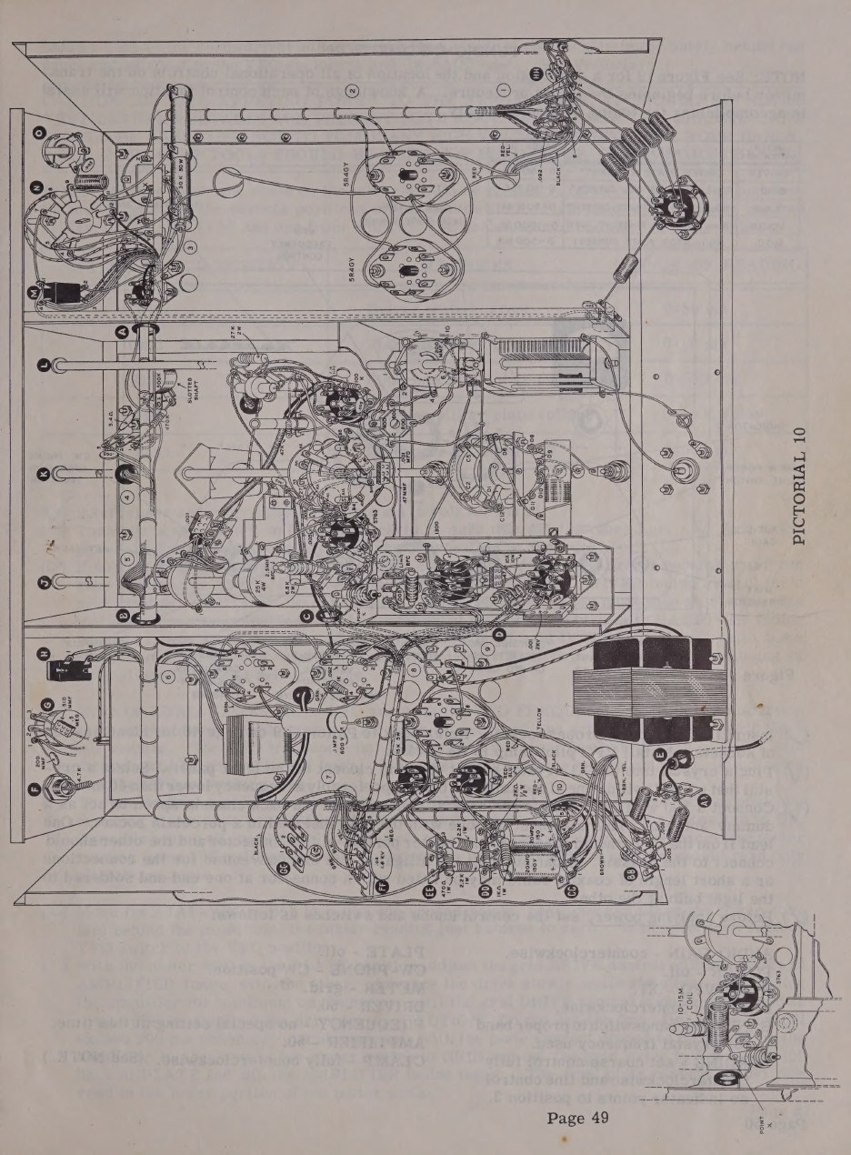
- step-by-step assembly and wiring, roughly forty pages of check-off lines, grouped by sub-assembly and keyed to Pictorials 1 to 10 and Figures 1 to 24;
- cabinet assembly;
- tuning instructions and VFO calibration;
- antenna notes, replacement policy, service, shipping instructions, specifications and warranty;
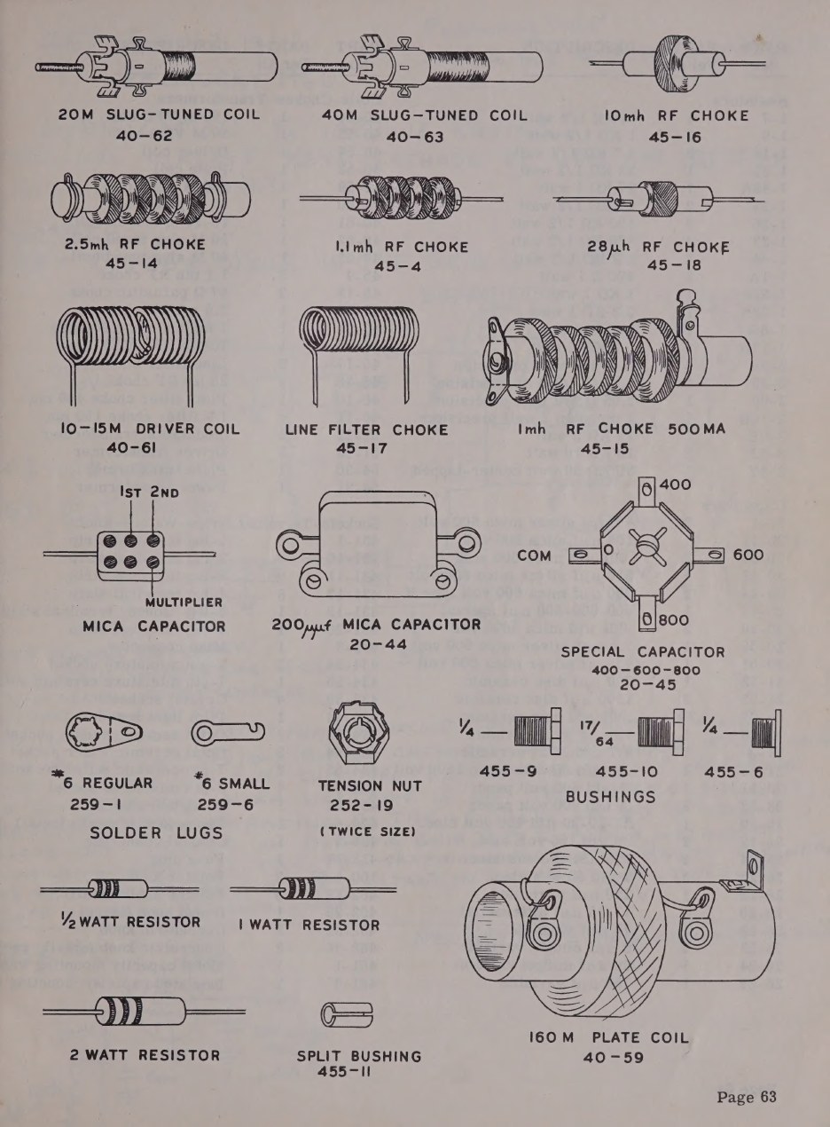
- the parts list, and a plate of component drawings.
The order of work is set by the section headings, and it is the unit method in practice. The builder starts with the chassis base, moves to the chassis top plate, and then wires one functional block at a time before the two halves of the chassis are ever joined:
- assembly and wiring of the chassis base;
- chassis top-plate assembly and wiring;
- partial wiring, and the audio section;
- oscillator stage wiring;
- driver stage wiring;
- partial wiring of the final amplifier;
- assembly of chassis top-plate and base - the point at which the kit becomes heavy;
- wiring in the modulator and power-supply compartment;
- wiring in the high-voltage power-supply compartment;
- wiring in the RF compartment;
- cabinet assembly;
- tuning and VFO calibration.
Each of those blocks is a sitting’s work, with its own pictorial, and each can be checked before the next begins. Every wiring line ends in (S) or (NS) - solder, or do not solder yet - because a terminal often takes three or four wires and is soldered once at the end. The builder is told to read each step through before starting it and to tick it off when done, “so it is easy to resume construction after your work has been interrupted”, which is a realistic view of how a 100-pound kit gets built in an evening at a time.
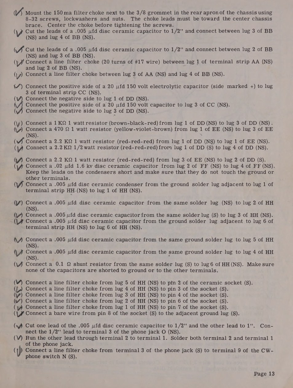
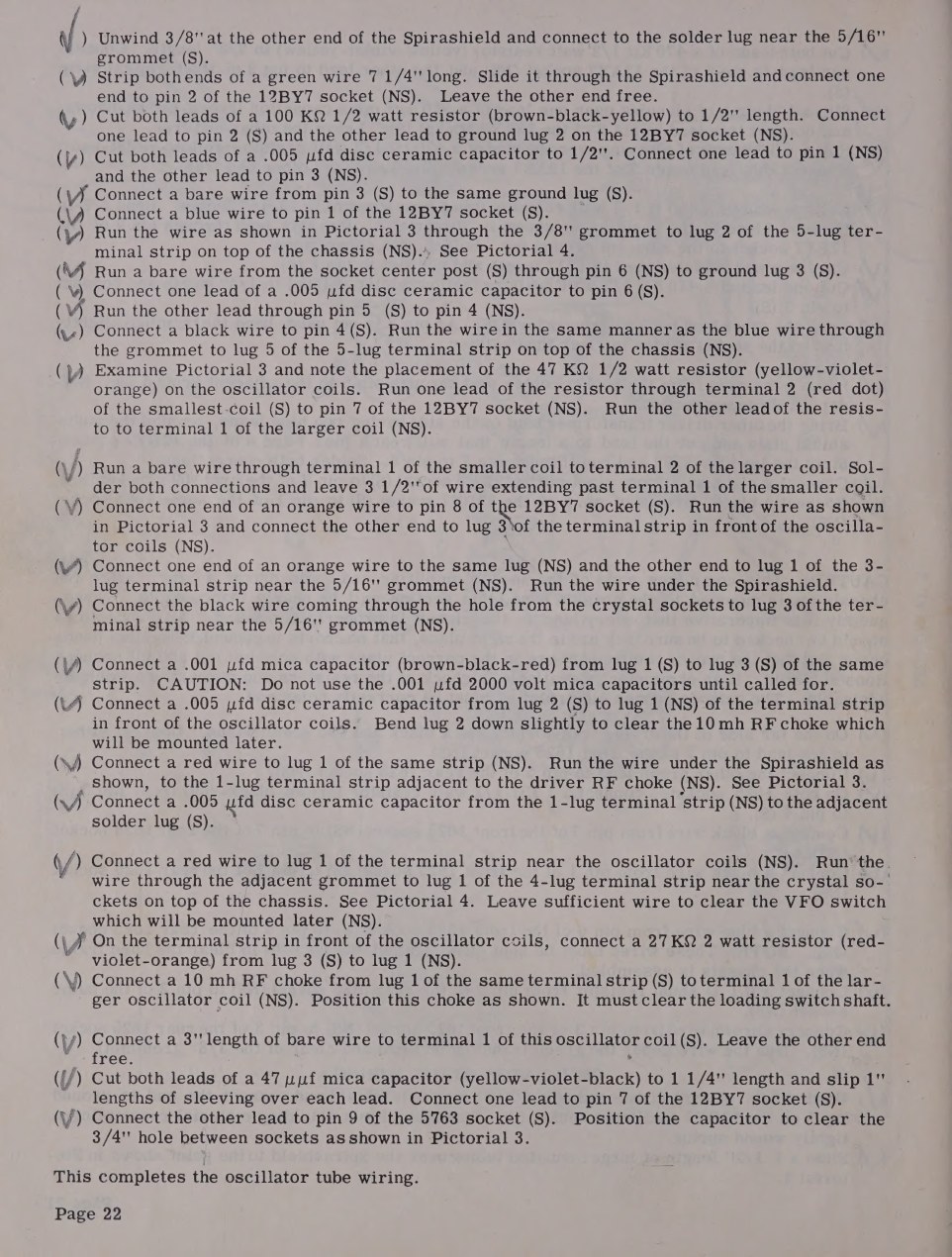
Heath’s advice on setting up the work is still good practice: take the large fold-in pictorial for the phase of construction in hand and pin it to the wall above the bench; identify the parts and lay them in a large shallow box; put a rag over the bench so the chassis is not marked; use a lockwasher under every nut unless a solder lug is used; use 1/4-inch 6-32 screws unless told otherwise. There is even a trick for a nut in an awkward place - press a piece of solder across one side of it with long-nosed pliers so that it jams in the threads and gives a handle.
3.3 Tools and skills
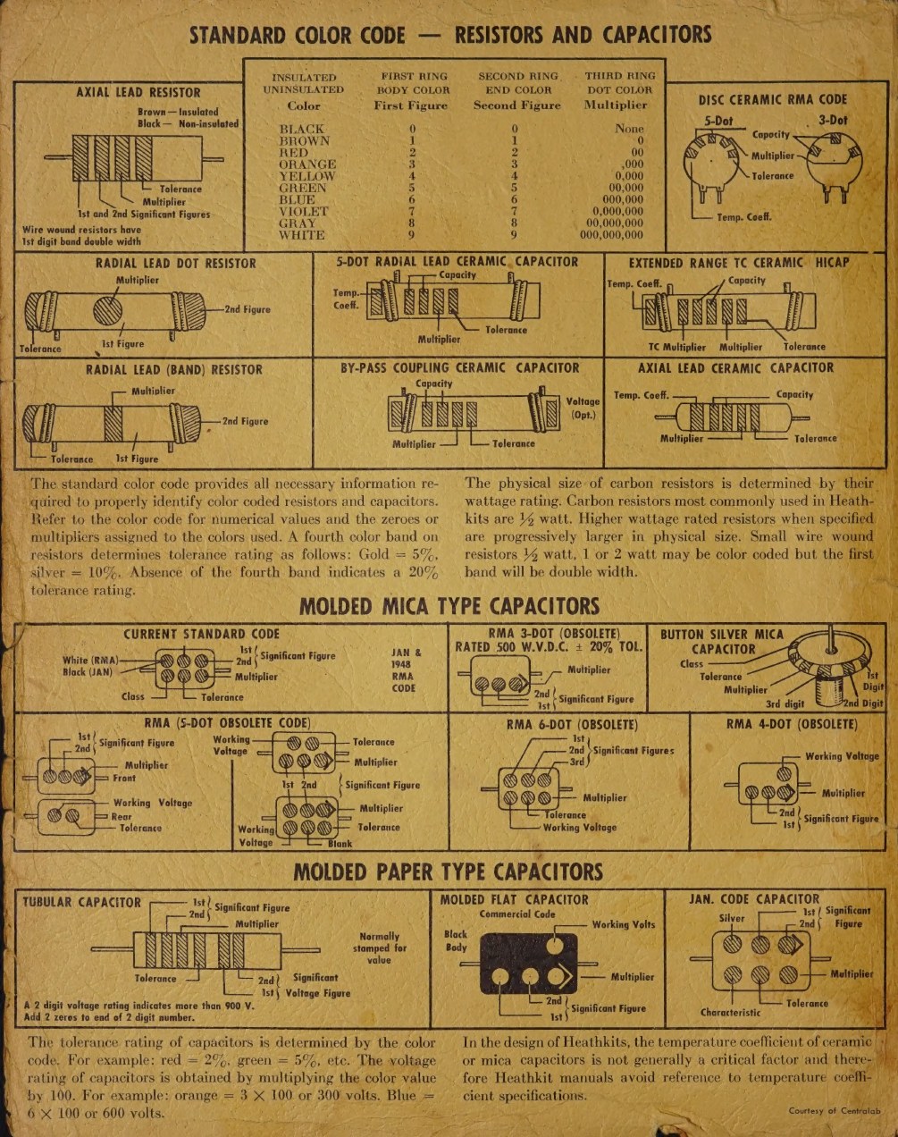
The manual’s inside covers do the teaching that the step lines cannot. One carries the Standard Color Code - resistors, disc ceramics, moulded mica and paper capacitors, each drawn with its bands or dots keyed to figures, multiplier and tolerance - with a note that Heathkit manuals avoid quoting temperature coefficients because the ceramic or mica capacitors used are not generally critical in that respect. The other is “Helpful Kit Building Information”: recommended tools, assembly practice, wiring practice, soldering, and a chart of schematic symbols.
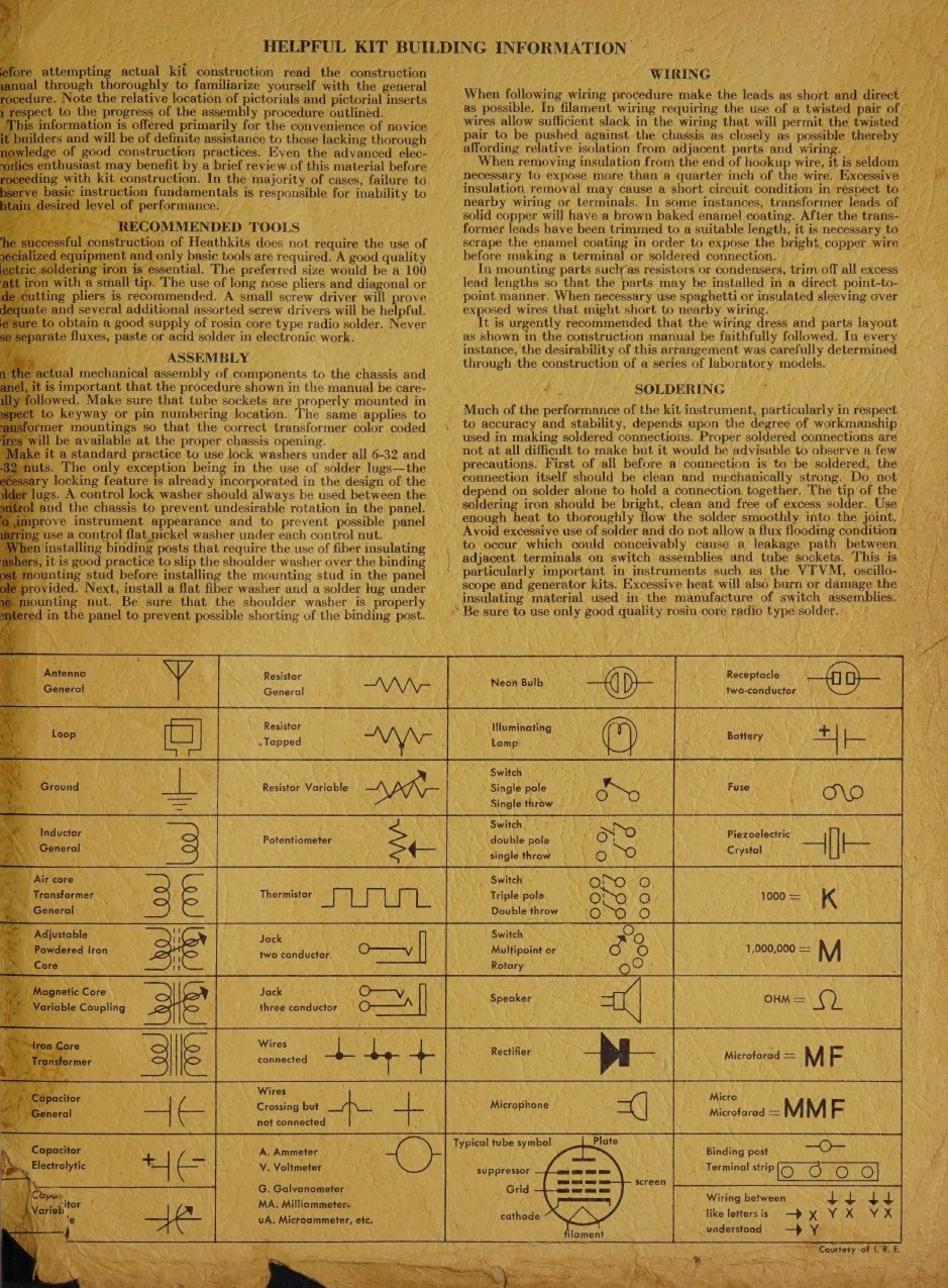
The tool list is short: a good soldering iron with a small tip, long-nosed pliers, diagonal cutters, “a small screw driver” and an assorted set of others, a knife for insulation, and rosin-core solder. The manual notes that no specialised equipment is needed. It does not assume a meter, although one is worth having. The only sharp instruction is about solder, and it is issued as a threat: “ALL GUARANTEES ARE VOIDED AND WE WILL NOT REPAIR OR SERVICE INSTRUMENTS IN WHICH ACID CORE SOLDER OR PASTE FLUXES HAVE BEEN USED.” Heath named acceptable brands - Kester “Resin-Five”, Ersin “Multicore” - and told anyone in doubt to buy a new roll marked “ROSIN CORE RADIO SOLDER”.
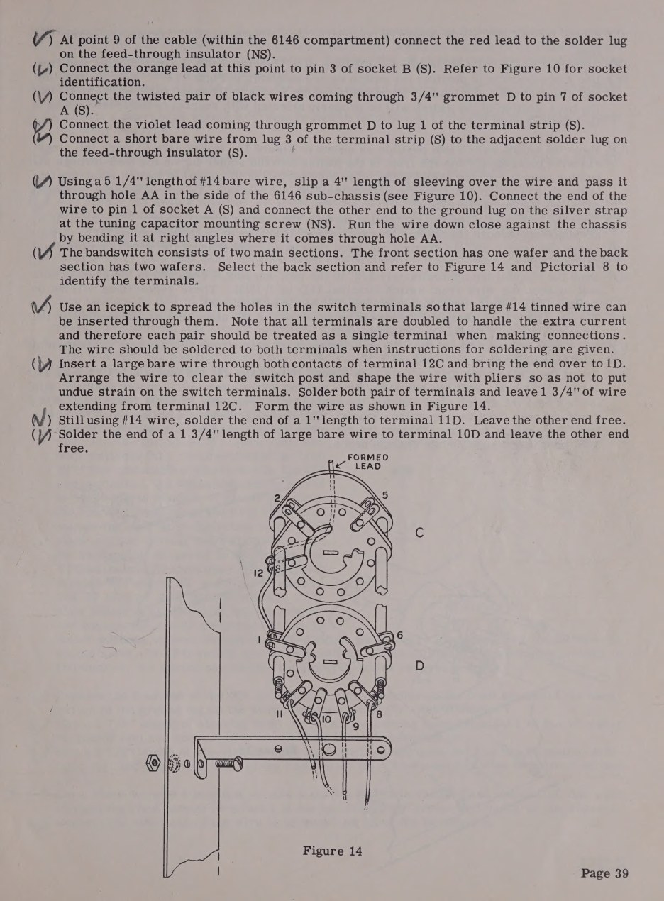
Two skills beyond soldering are needed. The first is reading a pictorial: the DX-100’s wiring is drawn rather than described, and a builder who cannot map the drawing onto the metal in front of him will get lost. The second is mechanical care. The chassis is 16-gauge steel with sub-chassis partitions; shafts have to be cut to length and coupled; the differential tuning capacitor and the VFO switch are mounted to tolerances that affect whether the dial tracks.
3.4 The cabinet is a kit of its own
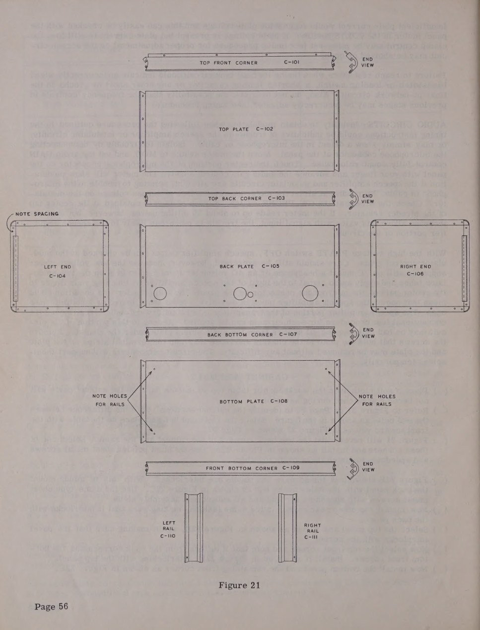
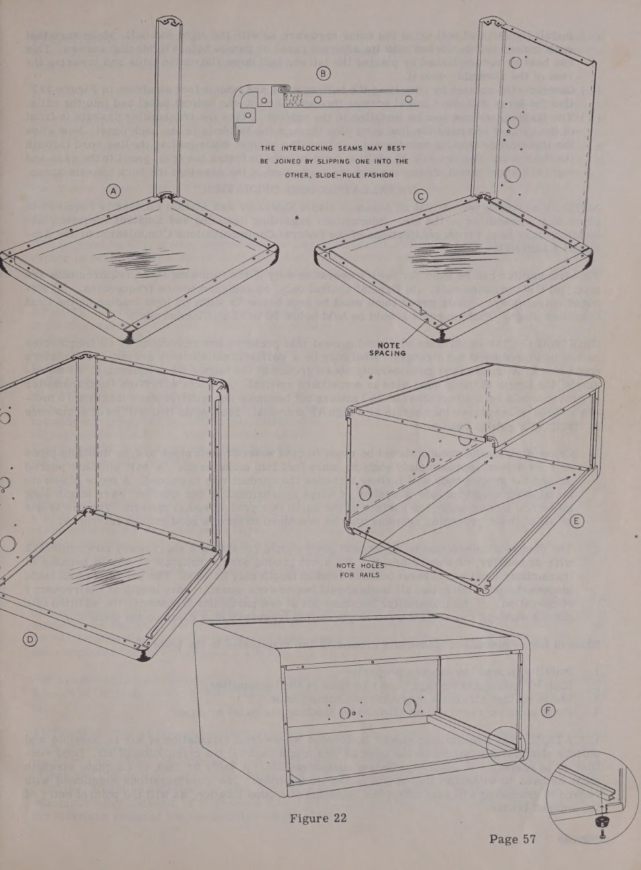
On the original DX-100 the cabinet arrives knocked down. Corner pieces, end bells, top, bottom and back panels are separate pressings, and the builder assembles them with self-tapping sheet-metal screws and speednuts, in an order that matters because the seams interlock - the same interlocking seams that the catalogue counts as one of the five TVI measures. The manual devotes Figures 21 and 22 and two pages of steps to it, opening with the instruction to place a soft cloth over the bench so the cabinet parts are not scratched, and warning that the two back corners are the same as each other but different from the front ones.
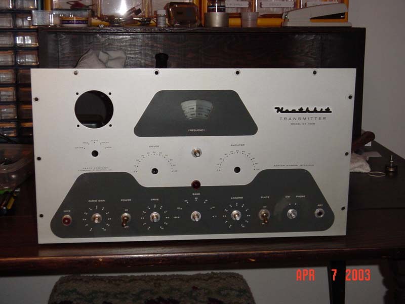
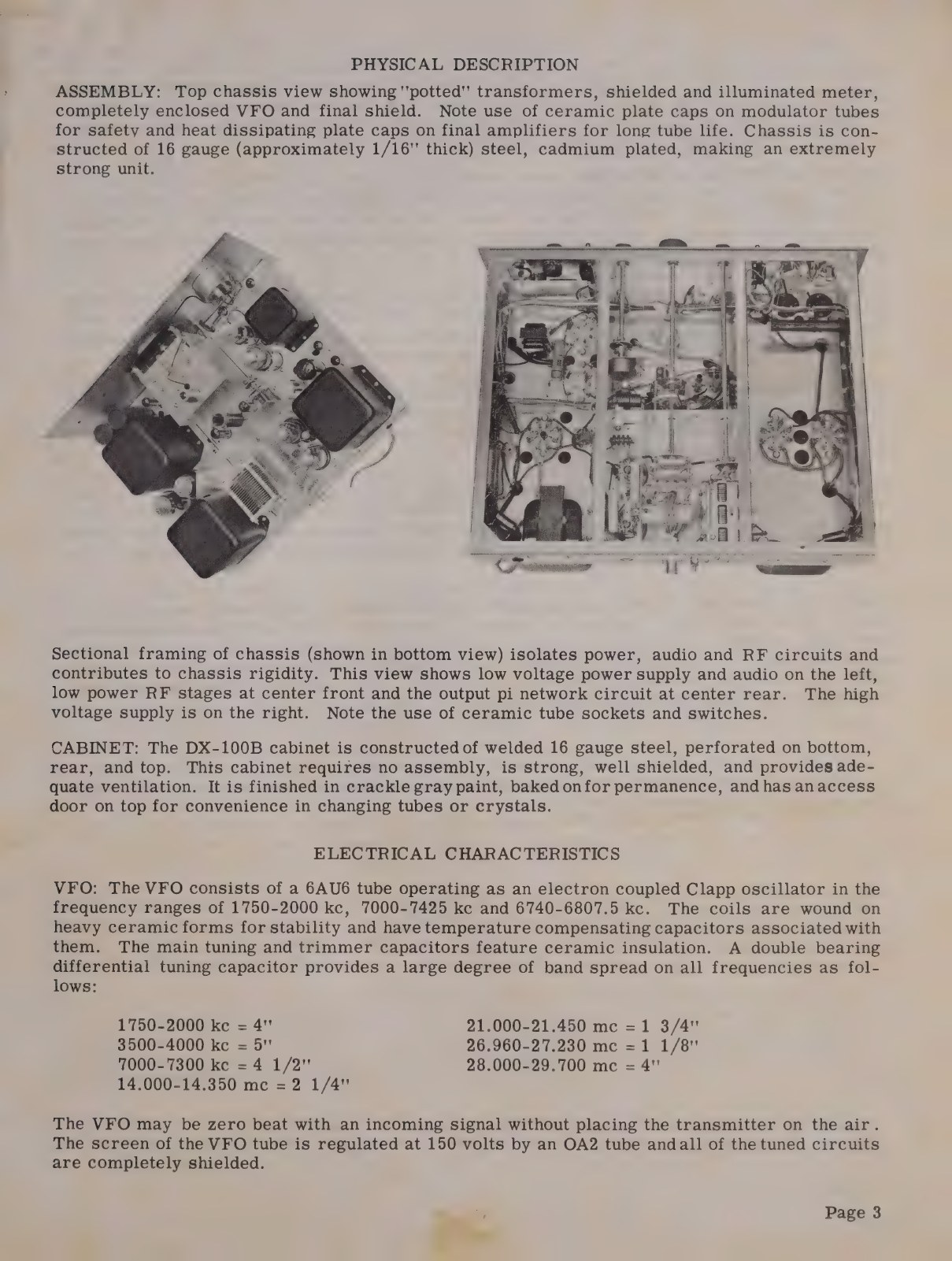
This is exactly what the DX-100B revision removed. Its cabinet is a single welded 16-gauge shell, perforated on the bottom, rear and top, finished in baked crackle grey, with an access hatch on top: “This cabinet requires no assembly, is strong, well shielded, and provides adequate ventilation” (DX-100B manual, p. 3). A builder of the B spends his time on the electronics instead.
3.5 The last steps before power
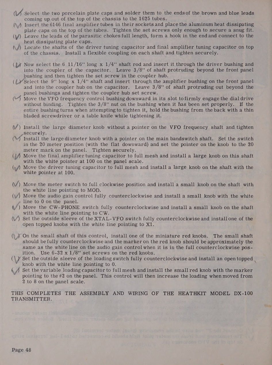
The final page of assembly reads like a checklist for a machine rather than a circuit: solder the two porcelain anode caps to the leads coming up to the 1625s; fit the 6146s and their aluminium heat-dissipating caps; leave the parasitic chokes full length, form a hook in the end and connect to the anode caps; cut and fit the shafts for the driver and amplifier tuning capacitors, with flexible couplings; set the bandswitch to 20 metres and fit the knob with its pointer on the 20-metre mark; set the tuning capacitors to full mesh and fit their knobs at 100 on the dial; set each switch to a defined position before its knob goes on. Only when the panel reads the same as the hardware beneath it does the manual say: “THIS COMPLETES THE ASSEMBLY AND WIRING OF THE HEATHKIT MODEL DX-100 TRANSMITTER.”
3.6 How long it took
Heath published no assembly time for the DX-100, and no contemporary figure has been found in the catalogues, flyers or the manual; claims of a particular number of hours should be treated as recollection rather than record. What can be said from the document is the shape of the job. The wiring alone occupies about forty pages of steps at a density of six to a dozen physical acts per page, each pictorial covering one compartment; the cabinet is a separate evening; the tune-up and VFO calibration another. Heath’s own framing - that the unit method turns one large project into several small ones - implies a kit meant to be built over weeks of evenings, not a weekend.
The testing that follows assembly is unusually consequential for a kit, because the first application of power puts 740 volts on an uncased chassis. The manual repeats the warning in three places, in capitals: testing happens with the transmitter out of its cabinet, and voltages “dangerous to life” are present at practically every point on the chassis.
3.7 What happened when it went wrong
Heath’s support arrangements are printed in the back of the manual and are part of what the $189.50 bought. Parts that failed to meet requirements were replaced free on request, provided the builder identified the part by its number and description from the parts list, gave the model number, the order number and date of purchase, and described the fault. Defective valves were not to be returned unless asked for. A completed instrument that would not work could be sent to the Heath Company Service Department for a flat service charge of $20.00 plus the cost of any additional material - a service policy that applied “ONLY TO COMPLETED INSTRUMENTS CONSTRUCTED IN ACCORDANCE WITH THE INSTRUCTIONS AS STATED IN THE MANUAL”. Instruments not completely finished, or modified in design, would not be accepted; anything showing evidence of acid-core solder or paste flux would be returned unrepaired. Kits returned for service had to be packed in a rugged wooden container with at least three inches of shredded newspaper on all sides, at the customer’s expense, and came back express collect. Factory repair service ran for one year from the date of purchase; beyond that, and for anything the manual did not cover, the builder could write to Heath’s Engineering Consultation Department. The parts warranty itself was three months (DX-100 manual, p. 62).
The effect of those rules on a beginner was that the manual had to be followed exactly, and the effect on Heath was that a kit could be supported at all. On modifications the company was politely unhelpful, and said so in print: it welcomed comments and suggestions, but it would not “design, test, evaluate and assume responsibility for proposed circuit changes for specific purposes”, and the builder was pointed at the library. That sentence is worth remembering when reading the modification literature that grew around the DX-100 within a year of its release.
Sources
- Assembling and Using Your Heathkit Transmitter Model DX-100: notes on assembly and wiring (p. 6), step-by-step instructions (pp. 7-48), cabinet assembly (pp. 56-57), service and warranty (p. 62), parts list and component drawings (pp. 63-64). DLARC scan, Internet Archive
- A second scan of the same manual, with loose pages and the note “No Copyright found”. DLARC, Internet Archive
- Assembly and Operation of the Heathkit Transmitter Model DX-100B, physical description p. 3. Internet Archive
- Heathkit 1956 catalogue, pp. 38-39 (pre-wound coils, pre-harnessed cable, potted transformers). World Radio History
Comments (0)