SB-104A Transceiver · Volume 3
Building the Kit
Heath’s launch copy was honest about the size of the job. The SB-104 had “over 2800 parts”, so it “won’t go together in just an evening or two”. The factory had “averaged about 50 hours in pre-production assembly” (Ham Radio, November 1974). The same paragraph promised that it went together “easier than any we’ve ever offered”. Both claims were true in their way. The kit’s mechanical construction was the tidiest Heath had yet produced: nearly everything on boards, two pre-laced harnesses, and a chassis of partitioned compartments. The difficulty lay elsewhere. A radio with this many solid-state parts, all of which had to be right, gave home construction very little margin for error. This volume describes the manuals, the order of assembly, the hard steps and what builders and repairers found afterwards.
3.1 How the manuals are organised
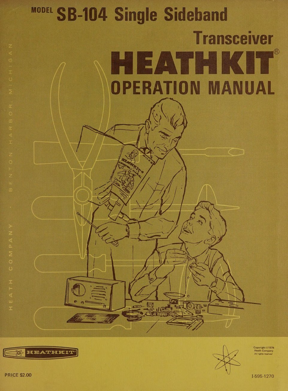
The SB-104 came with two bound manuals and an illustration booklet, and the page numbers ran on from one to the other. The Operation manual of 1974 begins at page 233 with “Test and Adjustments”. The Assembly manual therefore covered pages 1 to 232. The Operation manual runs on through Final Assembly, Installation, Operation, Troubleshooting and the Maintenance section, with one chapter per board, to the specifications, the theory of operation and the chassis photographs at pages 315 to 326 (SB-104 Operation manual). Pictorials too large for either book were placed in the illustration booklet, arranged “in the order in which you will use them”. General instructions on soldering, resistor colour codes and tools were not repeated. The manual refers the builder to the separate “Kit Builders Guide”.
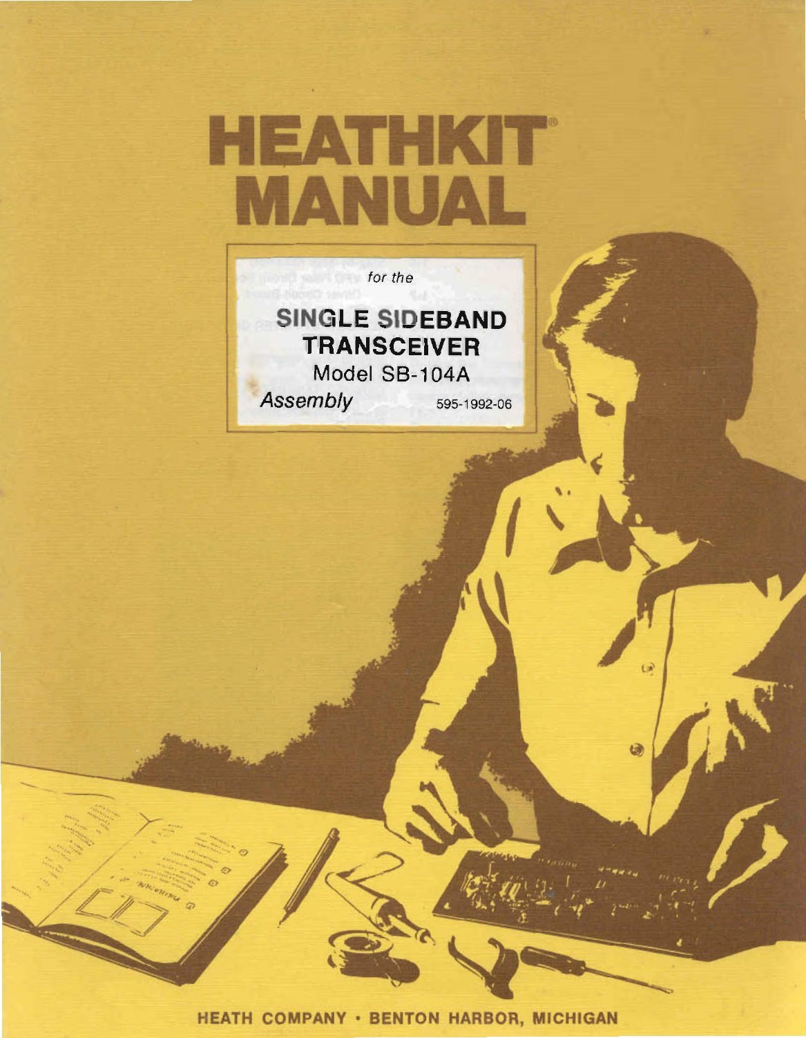
The SB-104A manuals keep the arrangement but number the pages by part. The Assembly manual, 595-1992-06, uses pages 1-1 to 1-198. The Operation manual, 595-1994-06, uses 2-1 onward. Both carry a 1977 copyright. The copies scanned are late printings: the Operation manual’s warranty page mentions Veritechnology, and the back covers carry the Heath/Zenith name.
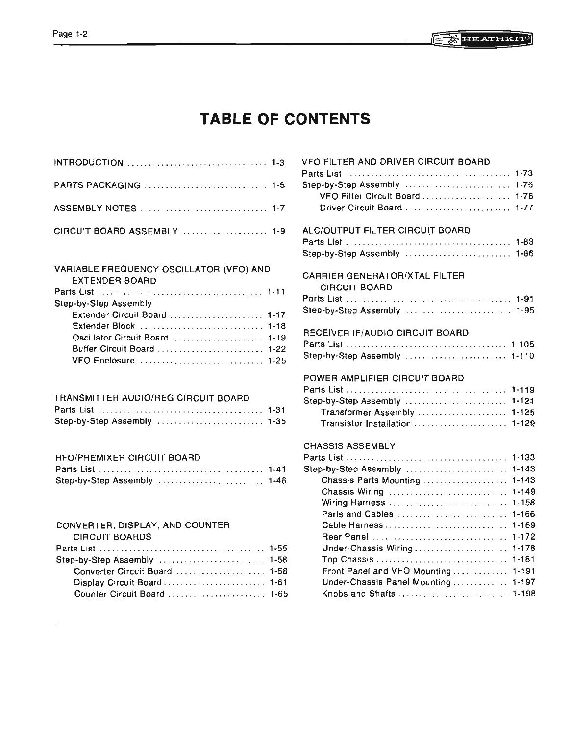
The Assembly manual’s table of contents shows the order of work. It is the order used by every Heath board-construction kit of the period: build every circuit board first, lay each aside, then build the chassis and bring the boards to it.
Table 1 — How the manuals are organised
| Section | SB-104A Assembly manual pages |
|---|---|
| Introduction, parts packaging, assembly notes | 1-3 to 1-9 |
| VFO and extender board (extender, extender block, oscillator, buffer, VFO enclosure) | 1-11 to 1-30 |
| Transmitter audio/regulator board (B) | 1-31 to 1-40 |
| HFO/premixer board (D) | 1-41 to 1-54 |
| Converter, display and counter boards (A) | 1-55 to 1-72 |
| VFO filter and driver boards (J) | 1-73 to 1-82 |
| ALC/output filter board (K) | 1-83 to 1-90 |
| Carrier generator/crystal filter board (E) | 1-91 to 1-104 |
| Receiver IF/audio board (F) | 1-105 to 1-118 |
| Power amplifier board (H), transformer assembly, transistor installation | 1-119 to 1-132 |
| Chassis: parts mounting, wiring, harnesses, cables, rear panel, top chassis, front panel and VFO, knobs | 1-133 to 1-198 |
Two boards are missing from that list, and both arrived ready-made. Board C, the transmitter IF, was built by the builder in the original SB-104 (the 1974 Test and Adjustments section checks its coils before plugging it in), but it has no section in the SB-104A manual. Bulletin SB-104-70 (August 1978) describes the “factory-built ‘C’ boards”: each is tested “on a special fixture for spurious and harmonic content”, its output-setting resistor is selected there, and it carries a 90-day warranty. The SB-104A’s new receiver front end, board G, also arrived assembled and aligned; the SB-104A Operation manual says it “was completely instrument aligned at the factory and should not require further adjustment unless a component is replaced”. That is the concrete meaning of the Fall 1977 catalogue’s promise of “reduced assembly time”.
3.2 Parts, packs and the first board
The kit arrived in a shipping carton holding a box marked “Packs 1–9”, plus loose parts too large for it, Pack #10. A “Pack Index Sheet” under the lid showed where each pack sat. Each board section opens with its own parts list and names the pack to open. The builder is told not to empty packs into a common pile: “to avoid intermixing parts, do not remove any of the parts packs from the box until you are directed to do so” (SB-104A Assembly manual, p. 1-5). The shipping carton also held a flattened, red-marked cardboard box. This was the board-return carton from the Circuit Board Service Policy, and the manual tells the builder to save it.
The assembly notes set the standard. The manual asks for a 15 to 25 watt iron with a 1/16 or 1/8 inch pyramidal or chisel tip, and rosin-core 60:40 or 50:50 solder. The warranty “will be void and we will not service any kit in which acid core solder or paste has been used”. Every part has a component number whose hundreds digit names its board, so the HFO board’s parts are numbered 400 to 499. The builder is asked to use those numbers when ordering replacements. The steps use Heath’s usual shorthand: “(NS)” for “do not solder yet”, and “(S-3)” for “solder, with three wires at the connection”.
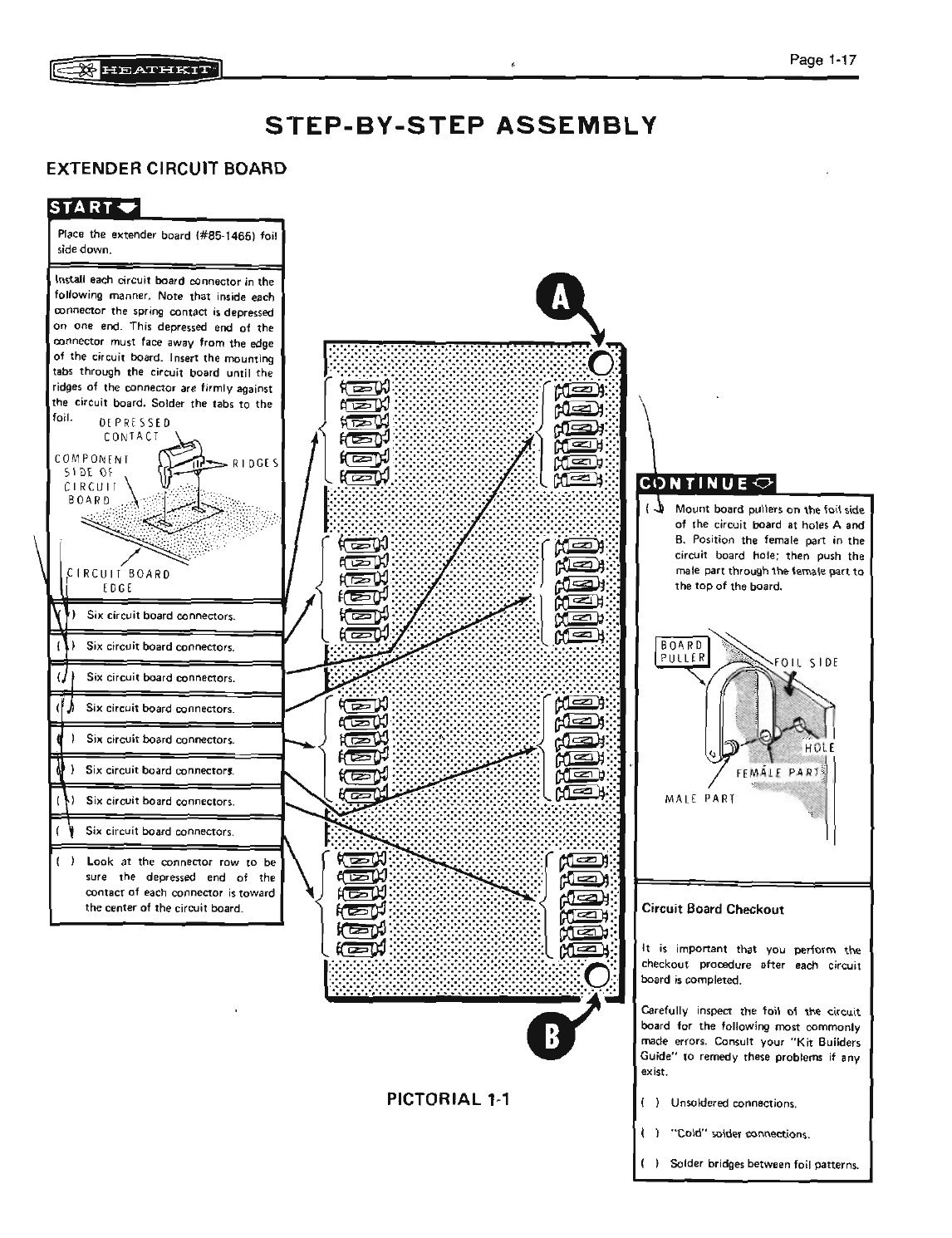
The first thing built is not part of the radio. It is the extender board, 85-1465, which lets any of seven boards stand above the chassis on live connectors for alignment and troubleshooting. It is also the first board the Test and Adjustments section calls for. The extender’s step list is short, and it ends with the “Circuit Board Checkout” box that closes every board in the manual: unsoldered connections, “cold” solder joints, and solder bridges between foils.
3.3 The boards
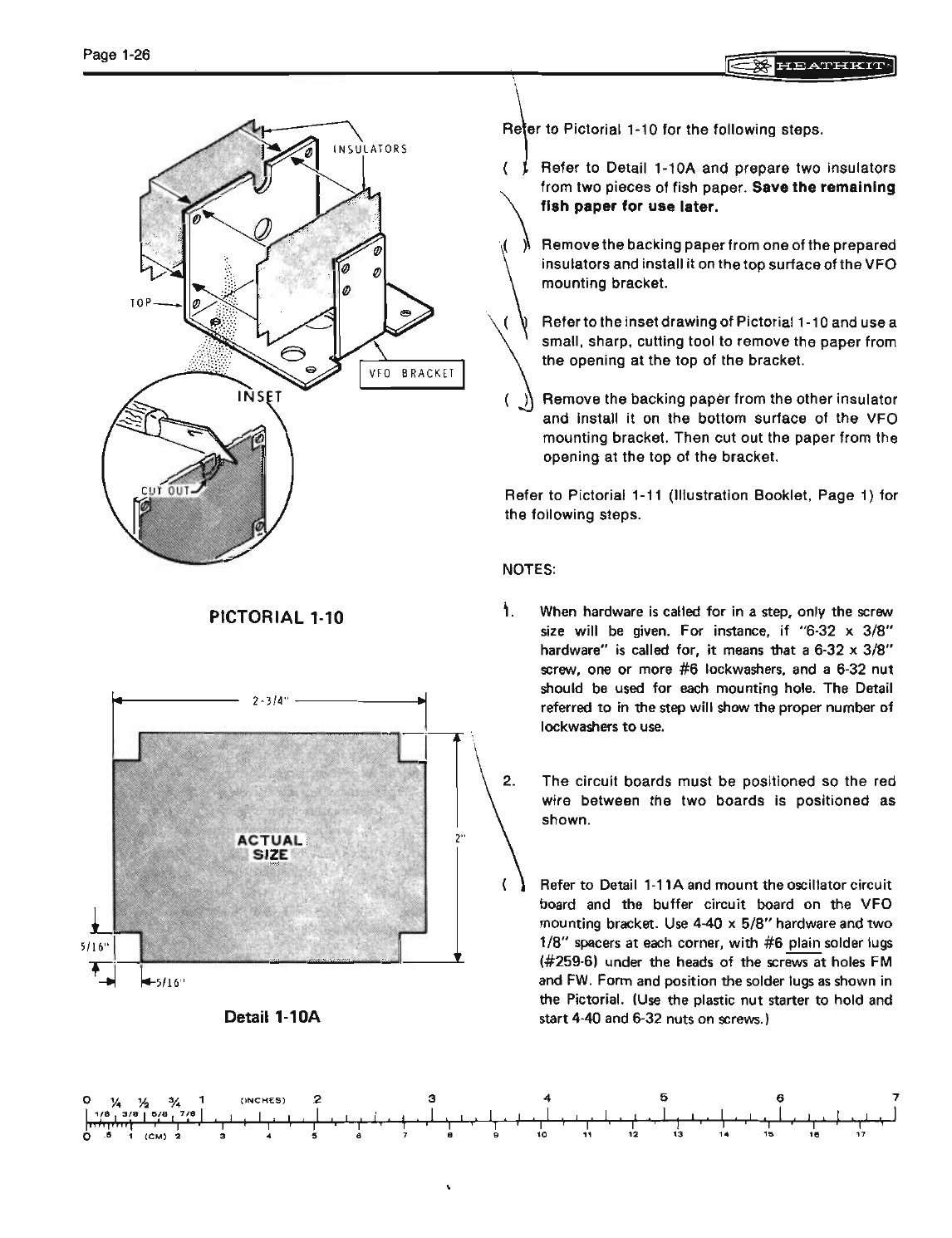
After the extender come the VFO boards and the VFO enclosure. The oscillator and buffer boards are mounted on a bracket with fish-paper insulators. The oscillator capacitors are cemented, and the pair of boards is bonded together. The VFO’s frequency depends on every part staying put, so the manual is exact about lead dress and cementing. The service literature explains why. Bulletin SB-104-10 (March 1975) warned that coil L1201 was supplied preset on the wrong peak and “if this coil is not adjusted on the peak near the front of the VFO, a shift problem and VFO instability will occur”. Bulletin SB-104-59 (February 1978) found VFOs that would not oscillate at all, because solder resist had not been scraped from the grounding pads at the board corners. K5BCQ adds that when the bond between the two VFO boards separates, the VFO drifts (K5BCQ).
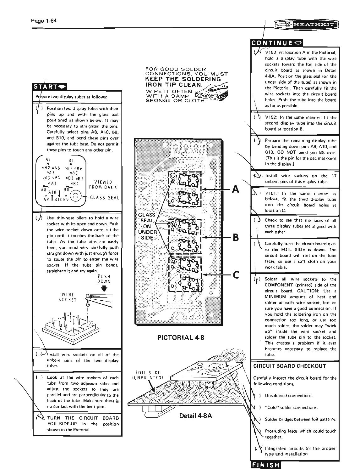
The counter and display boards are the kit’s digital section. They hold the integrated circuits and the six display tubes. The tubes sit in individual wire sockets that the builder solders into the board, cleaning the iron often. The manual’s cartoon reminder in the margin reads “keep the soldering iron tip clean”. The display board carries the 180-volt converter’s output. The Operation manual notes that it is the only high voltage in the transceiver.
The carrier-generator and IF boards carry the crystals, the crystal filter and its switching diodes, and the balanced mixers built from matched diodes. K5BCQ’s advice on these boards is emphatic. The mixer diodes are hot-carrier types that should be replaced only as a matched set, and a silicon signal diode such as a 1N914 must never be substituted, because “the resultant loss of low level signal sensitivity is dramatic”. The factory did not always get this right either. Bulletin SB-104-8 (February 1975) warned that “an undetermined amount” of incorrect diodes, with blue bodies (part 56-78 instead of clear-glass 56-87), had been shipped for the transmit mixer on board C. It added that “incorrect diodes may cause spurious radiation”.
Some parts were delicate for a kit builder to handle. The dual-gate MOSFETs are shipped with a shorting wire twisted round their leads, and the manual has the builder remove it after soldering. K5BCQ found a board with “low audio” whose IF FET still carried a fragment of that wire, invisible until the transistor was pulled.
3.4 The power amplifier
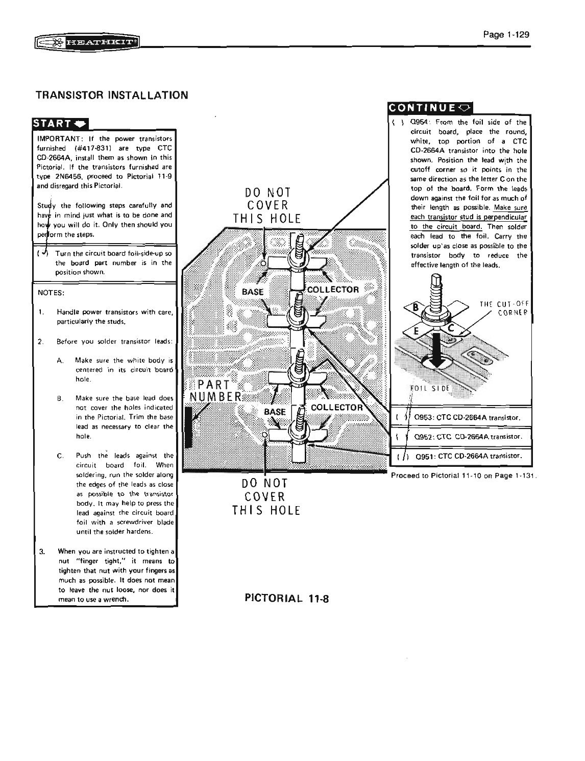
The power-amplifier board is the most expensive assembly in the kit and the one the manual handles most carefully. The four RF power transistors are stud-mounted. Their flanges pass through the board and their threaded studs go through the heat-sink plate. Their flat leads are soldered to the foil. The SB-104A manual’s “Transistor Installation” page opens with a boxed note. Heath part 417-831 might be either of two transistor types: if the furnished transistors “are type CTC CD-2664A, install them as shown in this Pictorial. If the transistors furnished are type 2N6456, proceed to Pictorial 11-9”. The builder is told to “study the following steps carefully” before doing anything. The page then shows the “DO NOT COVER THIS HOLE” positions, the part-number orientation, and how to bend the leads so the transistor body sits flat.
Heath had learned the stakes early. Bulletin SB-104-2 (January 1975) told service staff that once power had been applied and a single output transistor had failed, all four had to be changed. A transistor with a stud “broken off during construction” before power was applied could be replaced singly, but “with one from the same vendor”. The Circuit Board Service Policy sold replacements “only as a matched set of four” at $50.00 after the first year. Bulletin SB-104-7 (January 1975) added a warning about the drivers. If driver transistors ran hot, the first suspect was broken studs, because “there are instructions in the kit manual to prevent this type of damage for which Heath will not be liable if it occurs”.
The SB-104A changes brought one more pitfall. The SBM-104-2 update added four 360 pF capacitors to the foil side of the PA board. A vendor could not supply capacitors thin enough to fit between the board and the heat-sink plate, and tightening the heat sink could crack the board or break the transistors. Bulletin SB-104-60 (March 1978) records the problem; later update kits carried an insert telling the customer not to fit them, and production SB-104As had the capacitors moved to the component side. K5BCQ’s modern advice restates the mechanics. The four stud flanges must lie in one plane, the nuts should be tightened only enough to make heat-sink contact, and the stud should be held while tightening “to remove torque from the foil leads”.
3.5 The chassis and the harnesses
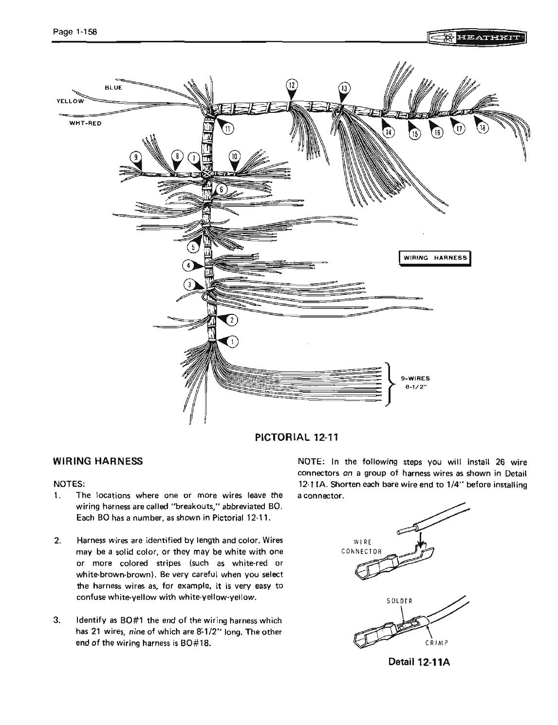
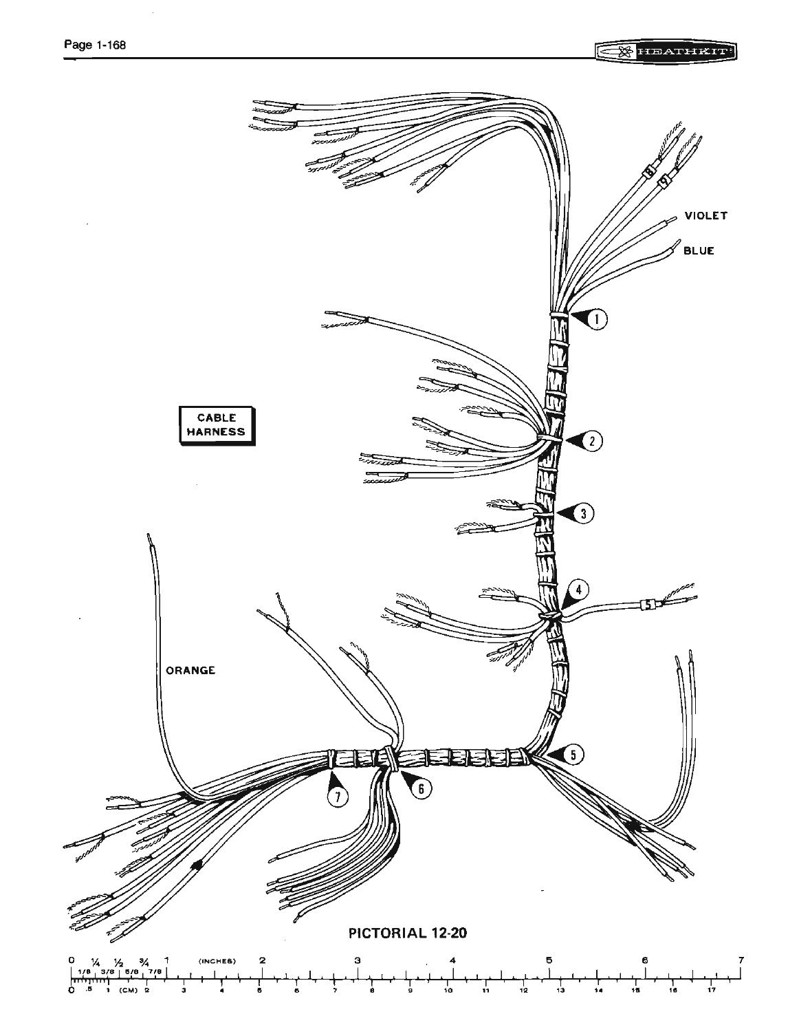
The chassis section runs to more than sixty pages. It covers the chassis parts, the partitions and card guides, the chassis pins that the boards plug onto, then two pre-laced wiring harnesses and a separate cable harness of shielded leads, the under-chassis wiring, the rear panel, the top of the chassis, and finally the front panel and VFO. The wiring harness has twenty-six wires to be fitted with crimped and soldered connectors before it goes in. Its branches are called “breakouts” and numbered BO#1 to BO#18, so each step can name the branch it uses.
The harness was the source of one production error. Bulletin SB-104-36 (April 1976) found kits of series 05551 whose harness had two identical white-brown-brown wires, or two white-brown wires, where it should have had one of each. That miswires the unit, and store stock had to be checked. A chart in the Operation manual gives the colour and type of every wire at every chassis connector, and warns that it “does not specify the source of each wire”.
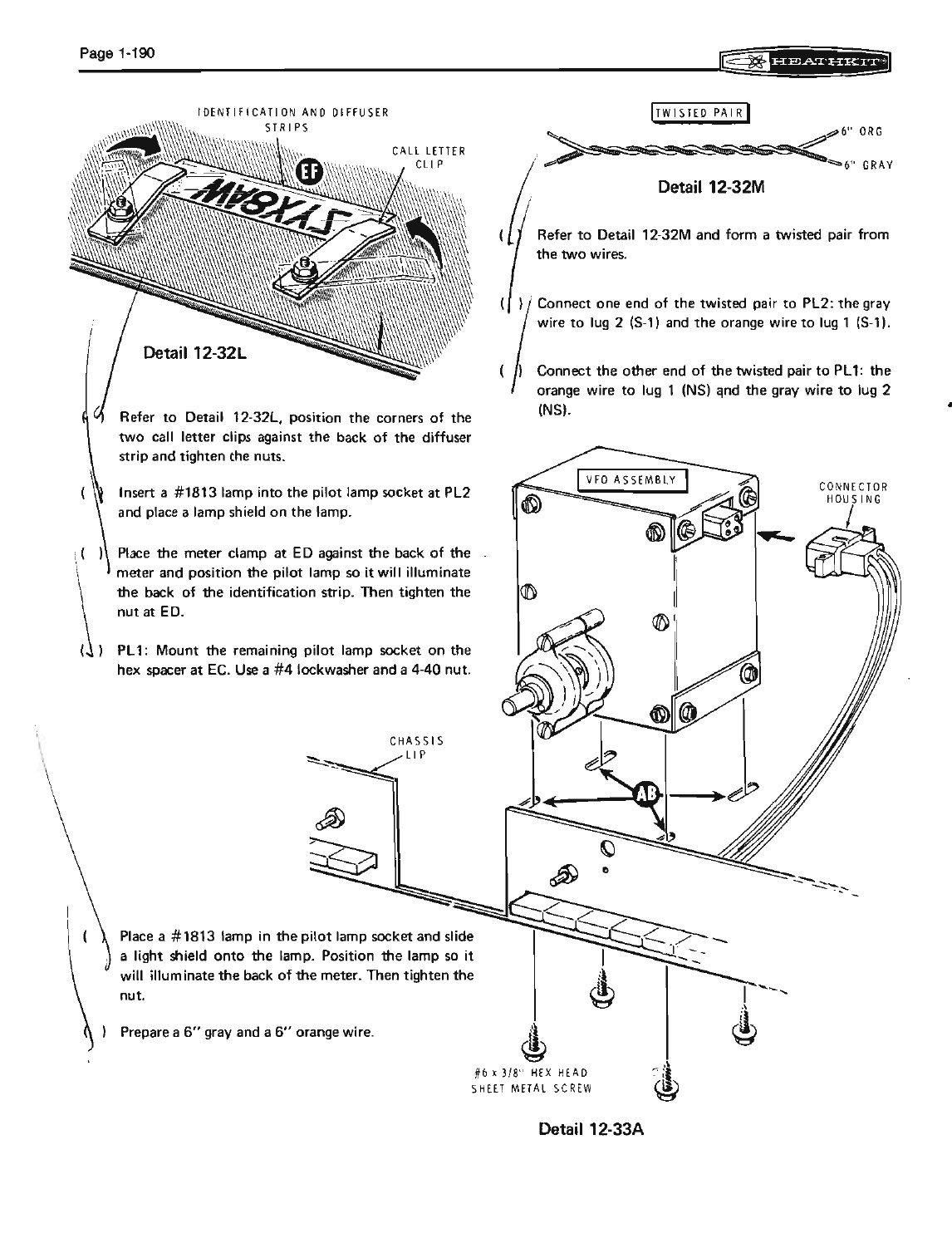
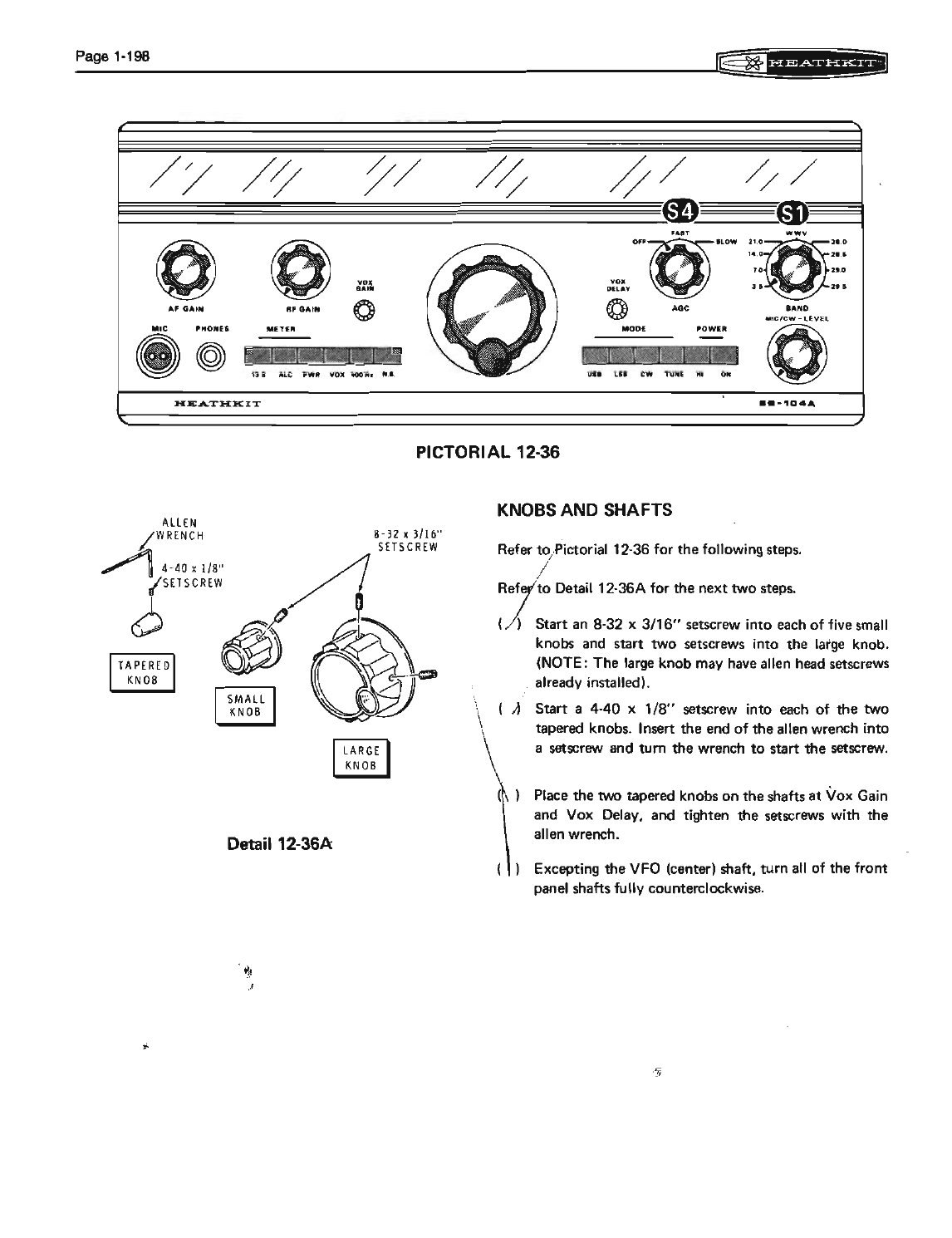
The front-panel steps include one small pleasure. The display window has a space for the owner’s call sign, and the kit supplied letters and numbers to spell it out on a clear strip that the pilot lamps light from behind. Heath had mentioned it in the launch advertisement: “we’ve even designed-in a place on the readout panel where you can light up your call sign when you build the SB-104 … we give you all the letters and numbers you need to do it.”
3.6 Test and Adjustments as part of the build
The build does not end when the last knob is on. It continues into the Operation manual’s Test and Adjustments section, where the boards are plugged in one at a time and checked before the next goes in. Each step has a boxed “Possible Cause Chart” beside it, and the manual insists: “If you have a difficulty, DO NOT proceed until it has been corrected as, in some cases, damage could result.” The Alignment and Use volume gives the sequence. For a builder it was the moment of truth. Board B first, and the display should read FFFF.F. Board A next, and the display should read 6603.6 on USB.
Heath’s claim that alignment “requires only a dummy load, mike and VTVM” held up because the rig supplies its own test signals. The counter’s radiation serves as the signal source for peaking the receiver’s filters, the built-in meter reads the transmitter, and WWV sets the counter’s clock. The manual allows that a signal generator and audio voltmeter “may be able to improve the filter response to a small degree”.
3.7 What it took
Heath’s own figure is the only hard number found for building time: about 50 hours in pre-production assembly, by people who built kits for a living. No builder’s log with a measured time has been found for this dive. Accounts from the period and later agree on the pattern. The mechanical work was straightforward, and getting the finished rig to meet specification was not.
The two company historians disagree mainly in tone. Chas Gilmore, a Heath employee at the time, said the rig “turned out to be fairly difficult to build”. Brueschke and Mack, citing Penson, wrote that “many were sent back to Heath several times and still would not work right” (EEJournal, part 3; Brueschke and Mack). K5BCQ, who repaired many of them, took the opposite view of the kit itself: “contrary to rumor, it’s a very straight forward design and was/is not really a complex kit to build (a credit to the Engineers at Heathkit…)”. He also warned that because they were kits, nothing should be assumed about a used one. He had found “missing components, incorrectly installed components, solder blobs shorting board traces, and wrong value components installed” (K5BCQ).
Two faults recur in the repair literature often enough to count as build hazards. WB4KDI reports that the 47 µF tantalum capacitor C2 across the ALC pins of driver board J “is consistently shown wired incorrectly”. The ALC voltage is negative, so the capacitor sits reverse-biased, and “most HW/SB-104 transceivers have this capacitor wired wrong!” He replaces it with a 1 µF aluminium electrolytic of the correct polarity (WB4KDI). K5BCQ and Heath’s own bulletins both point at the peaking coils on board C. Their bare wires stand close to the partitions, and if one touches the shield it shorts the 11-volt supply (bulletin SB-104-71, August 1978). The cure is a piece of fish paper on the shield and a look down from the top before power is applied.
The SB-104A’s Assembly manual is noticeably more careful than the first edition must have been, judging from the bulletins that corrected the original. The SB-104A’s success as a kit owes as much to the boards Heath took back to the factory as to anything the builder did.
Sources
- Heath Company. Heathkit Manual for the Single Sideband Transceiver Model SB-104A, Assembly, 595-1992-06 (copyright 1977). PDF, retronik.silicium.org · RigPix
- Heath Company. Heathkit Operation Manual, Single Sideband Transceiver Model SB-104 (copyright 1974). Internet Archive (DLARC)
- Heath Company. Operation manual, SB-104A, 595-1994-06 (copyright 1977). RigPix
- Ham Radio, November 1974, Heathkit centre spread. PDF
- Heath Company, SB-104 service bulletins SB-104-2, -7, -8, -10, -36, -59, -60, -70, -71 (1975–1978), W7LPF transcription. Nostalgic Kits Central
- K5BCQ. “Heathkit SB-104, HW-104, SB-104A Transceiver Repair.” Link
- WB4KDI Engineering Notebook. “Help! I Just Got a SB/HW-104.” Link
- Brueschke, Erich E., and Michael Mack. “The History of the Heath Companies.” AWA Review 32 (2019). Internet Archive
- Leibson, Steven. “‘H’ is for Heathkits and Hams: Part 3 – The 1970s.” EEJournal, 2025. Link
Comments (0)