SB-104A Transceiver · Volume 4
Alignment and Use
A tube rig is aligned once and then tuned every time the band changes. The SB-104 reverses that. Once its boards are aligned there is nothing to tune: the operator picks a band and a mode and talks. The alignment itself is also different. It happens board by board, as each board is plugged in, and it relies on the rig’s own counter, meter and signals rather than on a bench of test equipment. This volume outlines that procedure and its key points, not a copy of the manual, and then describes the controls and how the rig was meant to be operated.
4.1 Before any of it
The SB-104 has no reverse-polarity protection. K5BCQ, who repaired many of them, puts it plainly: “If you momentarily reverse the power you will probably take out the regulators and Q207 on the ‘G’ board …and more”. He recommends adding a protection diode and never improvising the 11-pin power connector (K5BCQ). The supply must deliver 13.8 volts under load at up to 20 amperes. Heath’s own service hint for low power, bulletin SB-104-6 of February 1975, begins with that figure measured “under load, at the transceiver”. Two further rules run through the whole procedure:
- Turn the transceiver off before inserting or removing any board. The manual prints this in capitals at every step where a board moves.
- Transmit only into a 50-ohm dummy load rated for 100 watts until the procedure says otherwise, and in HIGH power keep to the duty cycle given below.
4.2 The equipment
Heath’s claim was that alignment needs “only a dummy load, mike and VTVM” (Christmas 1975 catalogue). The Test and Adjustments section asks for a voltmeter with at least one megohm input impedance, a 100-watt 50-ohm dummy load, a microphone with a push-to-talk switch, and a station speaker. The kit supplies an extender board and an alignment tool.
The rig supplies its own test signals. For the receiver’s filters, a shielded cable is soldered to a test point on the counter board A. The counter’s own signal, fed to the antenna jack, is peaked on the receiver’s S-meter. The manual allows that a signal generator and an audio voltmeter, if available, “may be able to improve the filter response to a small degree”. The counter’s reference is set against WWV at 15 MHz or the Canadian station CHU at 7335 kHz.
The factory’s service departments used much more equipment. Bulletin SB-104-11 (April 1975), Heath’s in-house “Check Out and Alignment Procedures”, lists a triggered oscilloscope of at least 15 MHz bandwidth (an IO-4510 or better), an RF generator with a calibrated attenuator such as the Radiometer MS-27G, and an audio generator. Bulletin SB-104-74 (October 1978) describes sweeping the premix and transmitter band-pass filters with Heath’s IG-57A sweep generator, to find the filter responsible when “the power may be low at one end or the other of a particular band” (SB-104 bulletins). Modern restorers go further again. K5BCQ calls a spectrum analyser with a tracking generator the best tool for the receiver front end.
4.3 The sequence
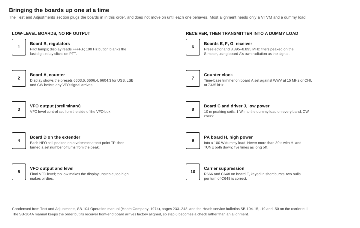
1. Regulator board B. With only the display, VFO, VFO-filter and converter boards in place, board B goes in first. When ON is pressed, the pilot lamps light and the display reads FFFF.F with the band switch at 3.5. Pressing the 100 Hz button should blank the last digit. Keying the microphone’s PTT switch should click the relay in and out.
2. Counter board A. The counter’s input cable is plugged into socket J101 on the board. With no premix arriving yet, the display shows the bare presets: the manual lists the reading expected for each of the USB, LSB and CW buttons. As How It Works explains, these are 6603.6, 6606.4 and 6604.3. A wrong reading points to the preset diodes or the counter ICs.
3. VFO output, preliminary. The VFO level control is reached through a hole in the side of the VFO box and set to its starting position.
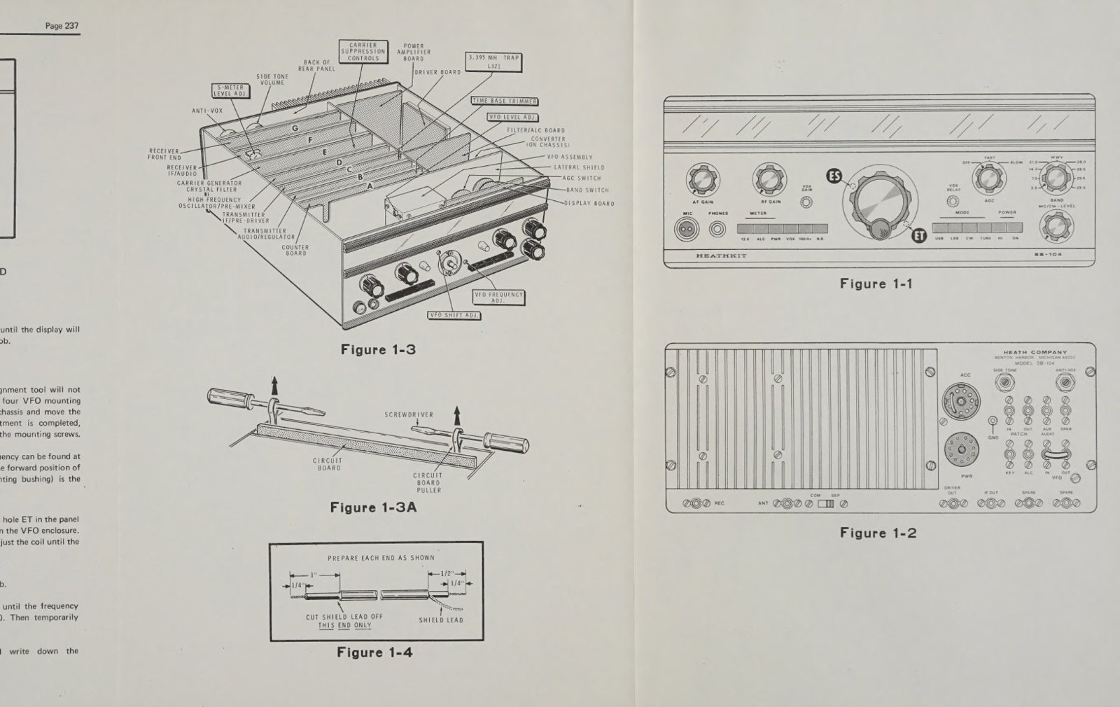
4. HFO coils, board D on the extender. The extender goes into compartment D and board D into the extender. Each band’s oscillator coil is peaked on the voltmeter at test point TP. The alignment tool carries a tape “flag” so its turns can be counted, and the manual’s chart specifies how many turns to back off from the peak. Two bulletins qualify this. Adjacent HFO coils can interact “to the point where one band may be completely inoperative”, so a dead band should first be checked against its neighbours’ coil settings (bulletin SB-104-9, February 1975). K5BCQ adds that each slug has two peaks, one with the slug out and one in. The “in” peak is the one to use, set on the gentle side of the curve.
5. VFO output and level. The final VFO level adjustment is the most consequential in the set. K5BCQ’s spectrum-analyser measurements show that too little drive makes the display unstable and too much makes birdies on receive and spurious signals on transmit. Bulletin SB-104-10 (March 1975) adds a mechanical point for the original SB-104. VFO coil L1201 must be peaked with its slug toward the front of the VFO. If it is left on the preset rear peak, the display will not agree between USB and LSB and the VFO drifts.
6. Receiver boards E, F and G. The carrier-generator, IF/audio and front-end boards go in. The counter-board test cable goes to the antenna jack, and the preselector trimmers for each band and the 8.395–8.895 MHz filter are peaked on the S-meter. The service bulletins record the trouble this step gave. Some trimmers ran fully open and had to be moved to a different fixed capacitor (SB-104-34). The 80-metre response was skewed toward the low end (SB-104-28). Several coils in the first three production runs were below their Q specification (SB-104-33). On the SB-104A this step changes. Board G arrives instrument-aligned, and the SB-104A manual’s procedure is to be used “only if a component has been replaced”. Even then, it notes, “some improvement may be noticed, especially on 10 meters, if the circuit board is instrument aligned” (SB-104A Operation manual, p. 2-95).
7. Counter clock. With an antenna connected, the receiver is tuned to zero beat on WWV (15,000 kHz) or CHU (7335.0 kHz) until the announcer’s voice sounds natural. The time-base trimmer beside the crystal on board A is then set until the display reads 15,000.0 or 7335.0. If it cannot be made to agree, the time-base crystal is out of tolerance.
8. Transmitter, low power. Before board C goes in, coil L321 (the 3.395 MHz trap) is checked flush with its form. The builder confirms that the board’s peaking coils clear the metal shield. This is the same hazard that bulletin SB-104-71 later found shorting the 11-volt supply. The driver board J is mounted and connected, the dummy load connected, and the 10-metre peaking coils adjusted for maximum meter reading. With PWR and TUNE pressed and the LEVEL control advanced, the meter should show output on every band except WWV. A CW check follows.
9. Transmitter, high power. The power-amplifier and filter boards go in, the chassis is closed up, and the rig is keyed into the dummy load in HIGH. The manual prints the rule in capitals: “Do not exceed 30 seconds in HI power and TUNE.” Each tune period must be followed by five times as long in receive, so ten seconds of tune needs fifty seconds off. Heath’s service hint for power output (bulletin SB-104-6) gives the tolerance as “100W +/- 1db, which means output power can be from 80W to 125W and be within specs”. Bulletin SB-104-33 adds that “too much power can cause additional problems. An ideal performance would be 100 W on all bands.”
10. Carrier suppression. The last adjustment is the carrier null on board E. The null control R666 and trimmer C648 are adjusted alternately with the transmitter keyed “for several short periods”, because “prolonged keying of the Transceiver while attempting to achieve an optimum setting creates an undesirable heat rise”. Three bulletins deal with this step alone. Bulletins SB-104-15 (May 1975), SB-104-19 (October 1975) and SB-104-50 (August 1976) all note that a good balance gives two nulls in one turn of the trimmer, either of which is correct. If only one appears, a 33 pF capacitor is removed or replaced with a 62 pF one, depending on which way the trimmer’s metal plate falls. Bulletin SB-104-33 offers a simple aid: listen on a second receiver and adjust for the lowest S-meter reading there.
4.4 What not to touch
One resistor on board C sets the transmitter’s output level, and later production fixed its value at the factory. Bulletin SB-104-70 (August 1978) records that the factory-built C boards were set “to 100 watts, +/- 1 dB” on a test fixture. R332 could be any of four values from 1180 to 1240 ohms, chosen for that board. It must always be replaced with the same value, and “any deviation from the selected resistor value on the ‘C’ board will void the warranty on the C board, driver board ‘J’, power amplifier board ‘H’ or ALC/Filter board, ‘K’”. A restorer who finds low power should look elsewhere first. K5BCQ’s list of real causes of low output includes an open driver RF choke, low drive from board D or E, and poor coaxial connections, rather than the finals.
4.5 The controls
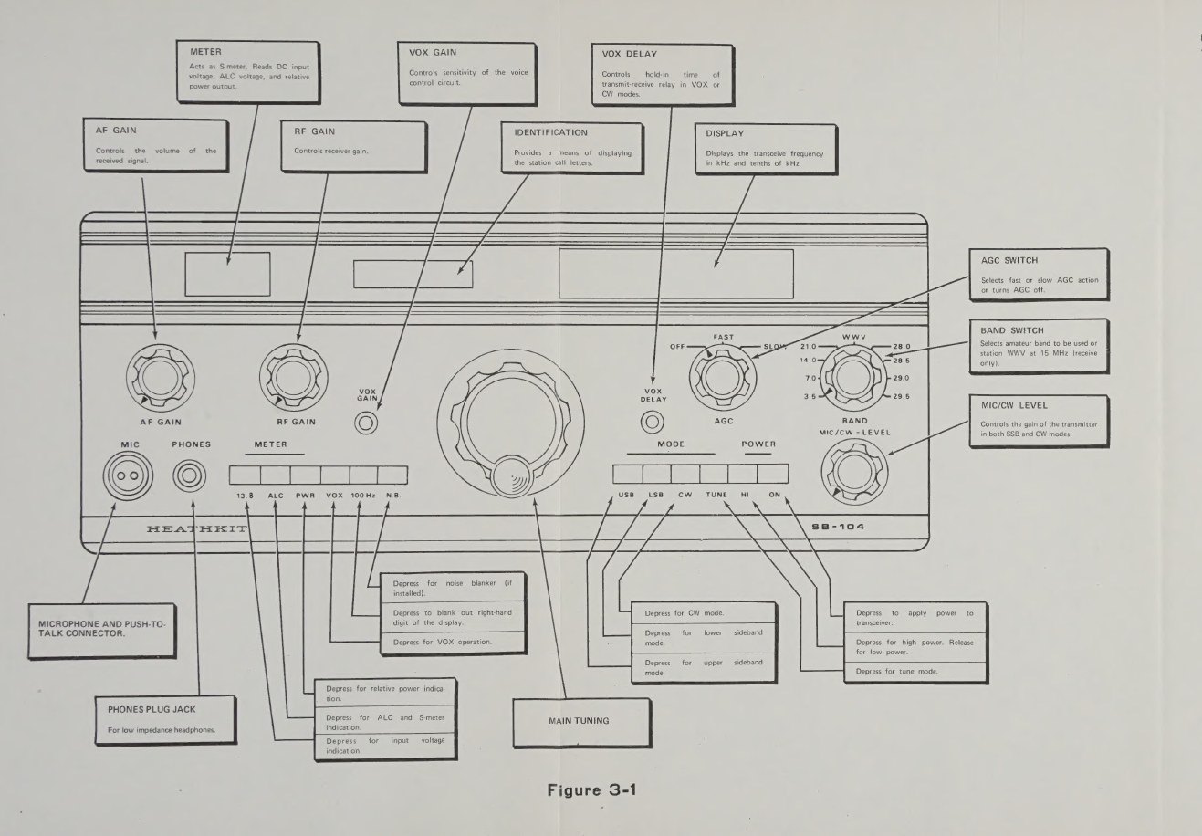
The front panel has five knobs, a row of meter pushbuttons at the left, a row of mode and power pushbuttons at the right, and a hidden meter behind the display window.
Table 1 — The controls
| Control | Function |
|---|---|
| AF GAIN | receiver volume |
| RF GAIN | receiver gain; a two-section control, one section shunting the front end and one setting IF gain |
| Meter buttons: 13.8, ALC, PWR | meter reads supply voltage, ALC, or relative power output; on receive, the ALC position makes it an S-meter |
| VOX | switches VOX on |
| 100 Hz | blanks the last (100 Hz) digit of the display |
| N.B. | switches the optional noise blanker |
| VOX GAIN, VOX DELAY | VOX sensitivity and hold time, on the front panel rather than the rear |
| Main tuning | the VFO, about 30 kHz per turn |
| AGC | OFF, FAST, SLOW |
| BAND | 3.5, 7.0, 14.0, 21.0, 28.0, 28.5, 29.0, 29.5 and WWV |
| MIC/CW LEVEL | transmitter drive, for both microphone and CW |
| USB, LSB, CW | mode |
| TUNE | a carrier for tuning an antenna coupler or loading a linear |
| HI | 100 W; released, the output is 1 W |
| ON | power (also switches an HP-1144 supply on and off remotely) |
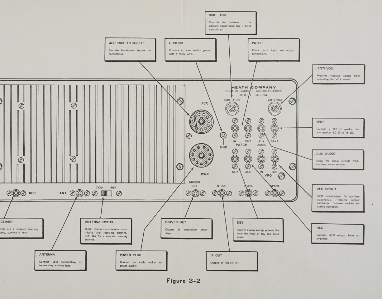
On the rear panel are the SIDE TONE level and ANTI-VOX controls. The phono jacks carry phone-patch in and out, auxiliary audio, speaker, key and ALC input from an amplifier. The VFO IN and OUT jacks are linked by a jumper that the SB-644 remote VFO replaces. There are driver and IF outputs, separate receive and transmit antenna jacks with a COM/SEP switch, and the 11-pin accessory and power sockets (SB-104 Operation manual, Figures 3-1 and 3-2).
4.6 Operating it
Receiving. The rig needs no warm-up and no calibration once the counter has been set against WWV. The operator selects a band and a sideband and tunes; the display shows the frequency to 100 Hz. The manual leaves the AGC speed to taste, observing that most SSB operators prefer SLOW. The WWV position doubles as a routine check of the display.
SSB. The manual’s procedure is short. Press ALC, USB or LSB, and ON; set the band. Then speak into the microphone and advance the LEVEL control “until the panel meter kicks up to approximately 3 (upper scale) on voice peaks”. Beyond that point the extra drive “will not increase the power output, and the final stage may be overdriven, which will result in clipping of voice peaks and sideband ‘splatter’”. HI is pressed only when 100 watts is wanted. VOX is set with VOX GAIN until the relay pulls in reliably, and VOX DELAY for the hold time.
CW. CW, PWR, VOX and ON are pressed. The LEVEL control is advanced “only to the point where the meter reading ceases to increase”. The warning follows: “a higher drive level will not increase the power output, but a keying ‘thump’ will develop”. VOX gain is set so the relay closes “instantly when the key is depressed”, which gives semi-break-in keyed by the sidetone. The SIDE TONE level is set on the rear panel.
The duty cycle. The Operation manual’s section on transmitting begins with a warning that no tube-rig manual needed: “The power transistors used in the power amplifier stage of this Transceiver are not as forgiving of overloading and misadjustment as vacuum tubes.” Its table sets the ratios for high power.
Table 2 — Operating it
| Mode | Transmit | Receive | Maximum continuous transmit |
|---|---|---|---|
| SSB | 2 units | 1 unit | 1 hour |
| CW | 1 unit | 1 unit | 15 minutes |
| TUNE | 1 unit | 5 units | 30 seconds |
In practice this rules the rig out of continuous-carrier modes at full power. Heath’s service department added one more limit. Bulletin SB-104-19 (October 1975) warns that “advancing the mike level control way beyond the normal operating point or using a speech processor fills in the valleys in the RF envelope and increases the output duty cycle”. Operators who insisted on doing so were referred back to the CW duty-cycle limits.
Antennas and couplers. The ALC reduces power into a high SWR, and the manual expects a coupler to be tuned in LOW power first: press PWR, TUNE and ON, advance LEVEL for a readable forward-power indication, and adjust the coupler for minimum SWR. HIGH power is used for tuning “only if the meter does not show an adequate reading when in low power”, and then within the 30-second rule. The manual suggests recording coupler settings per band. Mobile whip antennas, it warns, present a feed impedance of 15 to 20 ohms on the lower bands and must be matched before transmitting.
With a linear. The accessory socket provides relay contacts to switch an amplifier, and the ALC jack accepts its ALC. The manual’s caution is to advance the transceiver’s drive no further than the point where the amplifier’s output stops rising.
QRP. With HI released, the rig delivers at least one watt with fully solid-state switching. Heath’s catalogues sold this as a feature: the SB-104A’s one-watt position “turn[s] your 104A into Ham radio’s most sophisticated QRP rig” (Winter 1978 catalogue).
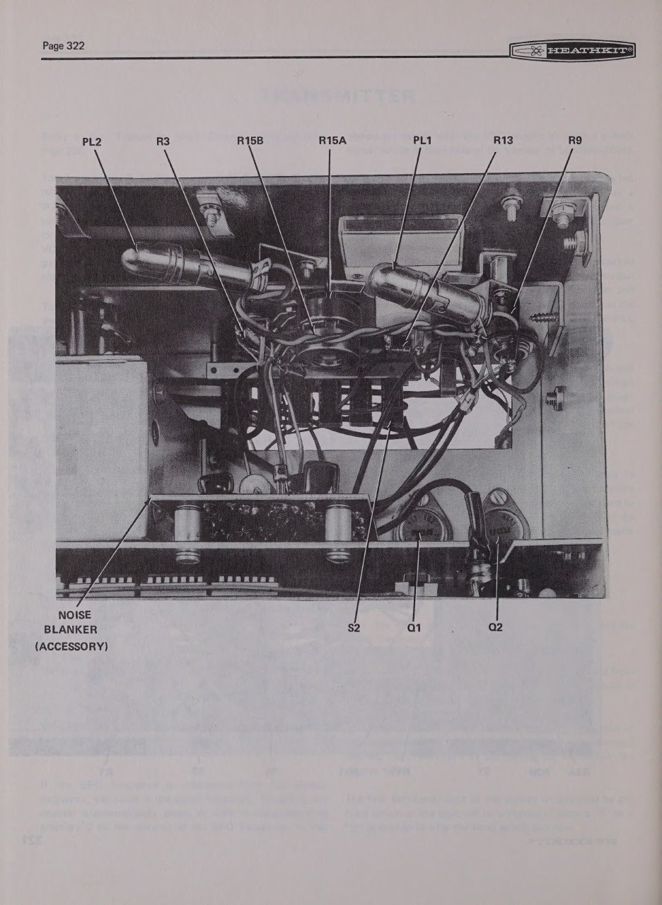
Mobile. The manual devotes several pages to mobile installation and ignition noise. It covers battery, alternator and regulator connections, which “may not be” the same from car to car, and the test for noise: run the engine with the transceiver on. The noise blanker was sold for this purpose. A later owner found a practical limit. In 73 Magazine, Paul Blum K9ARF reported that the 11-volt regulator “couldn’t maintain below 11.75 volts input”. The rig “started going crazy” on a car battery at low voltage, and it was stable down to 11.5 volts only after he redesigned the regulator (73 Amateur Radio Today, August 1998, pp. 10–12).
4.7 With the station accessories
The SB-644 remote VFO duplicates the transceiver’s VFO in a matching cabinet. A switching circuit allows transceive on either VFO, or transmit on one and receive on the other, and it has two crystal positions for fixed frequencies. Because the SB-104’s counter measures the premix, the display follows whichever VFO is in use; the SB-644’s own linear dial is only a reference. Bulletin SB-104-4 (January 1975) was needed to make the remote VFO shift frequencies correctly in low power. The SB-644A that replaced it in 1977 is marked in the catalogues as “Only for the SB-104A Transceiver”.
The SB-634 console adds a 24-hour clock, a 10-minute identification timer, an RF wattmeter reading 200 or 2000 watts, an SWR bridge, and a hybrid phone patch. The SB-614 monitor scope shows the transmitted envelope, for checking linearity, drive and splatter. The SB-230 linear raises the station to a kilowatt. The Reference volume describes each.
Sources
- Heath Company. Heathkit Operation Manual, Single Sideband Transceiver Model SB-104 (copyright 1974): Test and Adjustments; Final Assembly; Installation; Operation; Figures 1-3, 3-1, 3-2. Internet Archive (DLARC)
- Heath Company. Operation manual, SB-104A, 595-1994-06 (copyright 1977): Receiver Front End Alignment, p. 2-95. RigPix
- Heath Company, SB-104 service bulletins SB-104-4, -6, -9, -10, -11, -15, -19, -28, -33, -34, -50, -70, -71, -74, W7LPF transcription. Nostalgic Kits Central
- Heathkit catalogues: Christmas 1975 · Christmas 1977 · Winter 1978 · Winter 1983
- K5BCQ. “Heathkit SB-104, HW-104, SB-104A Transceiver Repair.” Link
- Blum, Paul (K9ARF). “A Silk Purse … Easy upgrades for Heathkit’s SB-104 transceiver.” 73 Amateur Radio Today, August 1998, pp. 10–12. PDF, World Radio History
Comments (0)