SB-104A Transceiver · Volume 5
Restoration and Common Faults
Two histories bear on any SB-104 on a bench today. The first is the factory’s. Between January 1975 and April 1989 Heath issued 103 service bulletins for the SB-104, HW-104 and SB-104A. It also sold two modification kits, and it returned every rig it serviced at the latest revision level. The second is the rig’s own history since. It was built by an amateur, probably modified, perhaps repaired with boards from another unit, and it has now spent forty-odd years with oxidising contacts, drifting resistors and ageing capacitors. This volume reads the first history for what it says about the second. It then sets out the known failures, the modern fixes and the published modifications.
5.1 Safety, first
The SB-104 has no mains voltage inside it, and it is easy to treat it as harmless. It is not.
- Current. The rig draws up to 20 amperes at 13.8 volts on transmit, from a supply or a battery that can deliver far more into a short. A dropped screwdriver across the PA supply, or a shorted tantalum capacitor, can start a fire. The supply should be fused as Heath fused it: the HP-1144 has a 20-ampere output fuse and a 7-ampere slow-blow primary fuse.
- Reverse polarity. There is no protection diode. A momentary reversal typically destroys both regulators on board B and other semiconductors (K5BCQ).
- The display supply. The 25 kHz converter makes 180 volts DC for the display tubes. The Operation manual calls it “the only high voltage used in the Transceiver”. K9ARF’s warning is to “be careful when poking around behind the display” (73, August 1998).
- Mains in the supply. The HP-1144/PS-1144 is a conventional 120/240-volt supply with a large transformer and filter capacitors. Its restoration follows ordinary mains-safety practice: unplug it, discharge the capacitors, and bring it up on a variac or a lamp limiter.
- RF. At 100 watts the antenna jack and the PA board carry dangerous RF voltages; K5BCQ measured about 100 V RF on the PA board. Transmit only into a dummy load during service.
- Power transistors. Stud-mounted RF power transistors of this era may contain beryllium-oxide insulation. The type fitted has not been confirmed here, so a damaged final should be treated as if it does: not cut, ground or crushed, and disposed of as hazardous waste.
5.2 Reading the factory’s record
The bulletins survive because Joe W7LPF transcribed Heath’s microfiche for the HEATH mailing list in 1997. His collection covers the SB-104 series from 1975 to 1989 (Nostalgic Kits Central). Some of the text is missing: the bulletins of 1977 and those of 1980 to 1983 appear there by date and title only, because the fiche had no text for them. The dates alone tell the launch story. Twenty-one bulletins appeared in 1975, and twenty-nine more by August 1976. Bulletin SB-104-40, dated 19 May 1976, is a four-page consolidated list of every change made “since introduction”, board by board.
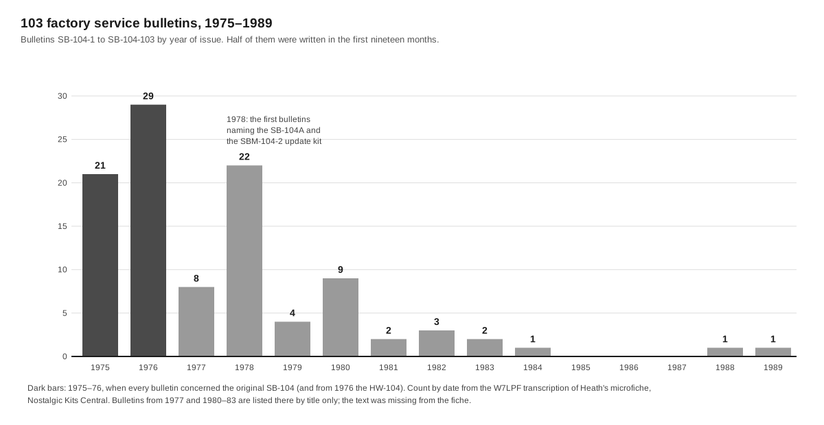
The problems the bulletins address, grouped by kind:
Table 1 — The problems the bulletins address, grouped by kind
| Problem | Bulletins (date) | What Heath changed |
|---|---|---|
| Final transistors failing | SB-104-2 (Jan 1975) | replace all four as a set if one failed under power; single replacement only for a stud broken in assembly, from the same vendor. Marked “not for general customer distribution” |
| Transmitted beat note in CW and TUNE, 700 Hz apart | SB-104-3, -15 (Jan, May 1975) | USB oscillator not fully disabled; timing components on board E changed |
| VFO frequency modulation on battery or mobile power | SB-104-13 (Apr 1975) | six VFO parts changed, including a 7.5 V zener for the 9.1 V; to be “installed in all units serviced” |
| Low power output | SB-104-6, -33, -41 (1975–76) | supply voltage, the 11 V regulator, a miswired ALC toroid; later a 1 % resistor at R332 |
| Receiver sensitivity | SB-104-21, -31, -33, -34, -35, -37 (1975–76) | new MOSFETs and coils on board G (the SBM-104-1 kit); coils below Q specification in “the first 3 runs” |
| Spurious and harmonic output | SB-104-22, -24, -26, -27, -30, -33 (1976) | ferrite beads for PA resistors, fewer turns on L952/L953, bypassing on the ALC line, a new 3.395 MHz trap, VFO pad no longer bypassed on 10 m |
| Oscillation | SB-104-7, -20, -33, -79 (1975–78) | ground clip on the 10 m coil shield; resistor across the driver choke for CTC transistors; driver board mounting holes left under solder resist; open coax shields |
| Keying, thumps and chirp | SB-104-7, -14, -17, -46, -80 (1975–78) | VOX “pop”; CW keying network; sidetone “blurp”; a larger filter capacitor against chirp; three causes of an RF burst on releasing PTT |
| Talkback and hum | SB-104-1, -23, -67, -96, -99 (1975–83) | rewiring, harness repositioning, audio-gain resistors |
| Display | SB-104-49, -82, -86 (1976–80) | VFO-line loading on 10 m; 200 D boards with a wrong transistor; “catastrophic failure” in the counter/display (text lost) |
| Overheating | SB-104-18, -39, -57, -61, -73, -88 (1975–80) | audio output emitter resistor, R11, driver idle current, a batch of CTC drivers with date code BY323 |
Two bulletins stand out for their tone. SB-104-7 (January 1975) notes that overheating drivers usually meant broken transistor studs, and “there are instructions in the kit manual to prevent this type of damage for which Heath will not be liable if it occurs”. SB-104-67 (May 1978) gives a set of wiring changes for “talk-back”. It then adds a far more drastic rewiring of the mode switches, to be done only “if a customer is not sufficiently placated; and only to avoid a refund”.
5.3 The modification kits
Heath sold two kits that are still found installed, or still being sought.
SBM-104-1, the sensitivity kit (instruction sheet 597-1576), is undated. Its changes are exactly those of bulletin SB-104-21 of November 1975, so it is the customer version of that bulletin. It changes two 40673 dual-gate MOSFETs at Q701 and Q704 for a different selection of the same type (Heath 417-274 instead of 417-240), replaces the 100-ohm resistor R719 with a 2.2 µH choke, replaces coil L734 with a 4.5 µH part, and reroutes the 13.8-volt feed past board G. The instructions end with a new piece of schematic “to tape over the corresponding part” of the manual’s fold-out (SBM-104-1, Internet Archive).
SBM-104-2, the update to SB-104A standard (kit part 830-24, manual 595-2016), brought in the new front-end board and the transmitter changes. Its manual went through at least four editions while bulletins corrected it. Bulletin SB-104-76 (November 1978) withdrew an instruction to cut a ground foil on board C, because cutting it put excessive 15-metre HFO signal on the antenna. Bulletin SB-104-78 withdrew the four 360 pF capacitors that could not be fitted under the PA heat sink without cracking the board. K5BCQ notes that the SBM-104-2 instructions are also the easiest way to tell SB-104 boards from SB-104A boards, which are “often swapped” (K5BCQ). WB4KDI’s site keeps a checklist of the kit’s chassis bypassing and termination changes (WB4KDI HW-104 index).
K5BCQ was told that “Heathkit always reworked units returned for servicing to the latest level”. A factory-serviced rig is therefore more likely to be up to date than one that never went back. In the other direction, K9ARF found factory repair stickers inside SB-104s marked “overvoltaged”. Heath had offered a kit to add crowbar over-voltage protection to the matching supply, and “many SB-104 owners became painfully aware of the need for this protective circuit” (73, August 1998).
5.4 Buying and first assessment
Three facts shape an assessment.
- It is a kit. K5BCQ’s advice is to assume nothing: “don’t automatically assume they worked at one (or any) time”. He has found missing parts, wrong values, solder bridges and misplaced components in rigs sold as working.
- It may be a mixture. Boards plug in and were traded, so an SB-104A may contain SB-104 or HW-104 boards and the reverse. HW-104 boards are orange-brown phenolic and SB-104 boards green glass-epoxy (WB4KDI). The board part numbers printed on each board identify its level.
- The display tells a story. A display frozen at 6603.6, 16603.6 or 26603.6 (the counter preset, depending on the band switch) with tuning having no effect usually means a dead 11-volt supply, not a dead counter. K5BCQ found exactly that on two rigs, one of them caused by electrolytic C6 shorting its case to the pass transistor’s 13.8-volt connection.
A first inspection, before any power, should check that the VFO jumper is in place between the rear VFO IN and OUT jacks. The accessory plug must have its pin 2 to pin 5 jumper. If the noise blanker has been removed, its socket must be jumpered, because otherwise the receiver has no signal path. The inspection should also look down between the boards and the partitions. K5BCQ singles out the peaking coils on board C, which “come really close”. Bulletin SB-104-71 records the result when one touches: a shorted 11-volt supply.
5.5 Bringing one up
K5BCQ’s order is the one the manual implies: check power first and recheck it at every board. Get the receiver working, from any noise at the speaker back to the antenna. Then work on the transmitter from the VFO toward the antenna. Pin 4 of the power plug feeds everything except the final. Feeding pin 4 alone brings up the low-level circuits safely with the PA unpowered (WB4KDI).
The first working session is usually spent on contacts. Each board has sprung fingers that grip the chassis pins, and both oxidise. K5BCQ cleans them with DeoxIT and bends the fingers slightly for firmer contact. Boards removed many times may also have worn the solder from their grounded side edges, which make contact with the card guides and matter for shielding; he restores them with copper tape. Every mounting screw that doubles as a ground, on the noise blanker and the driver board for instance, should be checked. Bulletin SB-104-33 had already found driver-board mounting holes left under solder resist.
5.6 What actually goes wrong
Regulators (board B). The 11-volt and 5-volt regulators are Motorola MFC6030 ICs driving pass transistors on the chassis. They are obsolete and fragile, and they are the usual casualty of a reversed or overvoltaged supply. K5BCQ rebuilt his with LM317 regulators and PNP pass transistors, with multi-turn trimmers for adjustment. K9ARF replaced the 11-volt regulator with an op-amp and a P-channel power MOSFET, which held regulation down to 11.5 volts input. WB4KDI replaces the 11-volt regulator with a low-dropout IC and the 5-volt one with a three-terminal regulator such as the LM323K. All three agree that the regulators should be set up with the other boards unplugged, and the other boards restored only when the rails are correct.
The relay driver. Transistor Q207 on board B is the other common victim of a reversed supply. A damaged Q207 can leave five or six volts on board B’s pin 6 in receive, which mutes the audio. Tashner’s 1981 modification replaces it with a heavier tab-mounted transistor and changes R217 from 4.7 k to 2.2 k to suit (Ham Radio, April 1981).
Tantalum capacitors. Tantalum capacitors fail short. WB4KDI’s most important single finding is that the 47 µF tantalum C2 on driver board J is “consistently shown wired incorrectly”. It sits reverse-biased on the negative ALC line, and he found shorted examples. He replaces it with a 1 µF aluminium electrolytic, negative lead to the ALC pin. He also had tantalum C3 short during testing, and replaced it with a 0.1 µF ceramic in parallel with a 1000 µF electrolytic.
The final transistors. Low power is often blamed on the finals and rarely caused by them. K5BCQ had “only found one case” where the finals were at fault. Most low-power rigs had an open choke on the driver board, low drive from boards D or E, bad solder joints, cracked foils at the transistor leads, or loose coaxial connections. His test sequence starts with DC at the PA. At the small board around L952 and L953 the bases should read 0 V in receive and about 0.65 V in transmit. Next he checks drive to the PA, about 8–9 V RF with the drive control fully clockwise. Then he disables the ALC for a few seconds into a dummy load; a healthy system gives about 175 watts on 80 metres. Only then does he test individual transistors, isolating them by cutting and later re-soldering their foils. Heath insisted on replacing all four as a matched set. K5BCQ has replaced two at a time successfully using transistors of reasonably matched beta. WB4KDI lists the original and later types (Acrian S30-12A, Microsemi 2N6456, CTC CD-2664A, TRW PT5757) and notes that Motorola MRF-series devices can substitute with mechanical changes. K5BCQ names the MRF455A. The 360 pF collector capacitors of the SB-104A should be present; if they are missing, K5BCQ fits them on the foil side with clearance under the heat-sink plate.
The drivers. The drivers are TRW PT6619 or CTC CD-3342 types. WB4KDI lists the 2N4127, KT920A and 2N6081 as possible substitutes. Heath’s bulletins found them overheating in standby, and a batch of CTC devices with date code BY323 that ran hot at idle (SB-104-73, September 1978).
Coaxial connectors inside. The boards interconnect through short coaxial leads with RCA plugs. Bulletin SB-104-79 (November 1978) traced PA oscillation at about 27 MHz, and at 21 MHz on 80 and 40 metres, to open shields at those plugs. K5BCQ advises pinching the four sides of each plug’s shield for grip, and replacing the rear-panel RCA antenna jack with a bulkhead BNC if its ceramic insert has deteriorated.
Display. The display tubes need 180 volts and their drivers are specialised parts. K5BCQ gives the DM8880 for the counter-display drivers. K9ARF could not find a replacement for the DD700 driver IC. He later found a factory-repaired board fitted with a more common SN75480N, also sold as ECG2028. Heath’s bulletin SB-104-86 (February 1980) is titled “Preventing Catastrophic Failure of Parts in Counter/Display Circuit”, but its text is among those lost from the fiche.
VFO. Drift can come from the bond between the oscillator and buffer boards separating. It can also come from the wires to the tuning capacitor moving near the rotor plates; K5BCQ suggests heavier wire. He traced one intermittent loss of drive to the 4-pin plug’s ground wire touching RFC1201 inside the box. Stiff or slipping tuning usually means the ball-reduction drive needs cleaning and fresh grease. K5BCQ reflows the old grease by heating the drive body with a soldering iron, rather than dismantling the tension tabs.
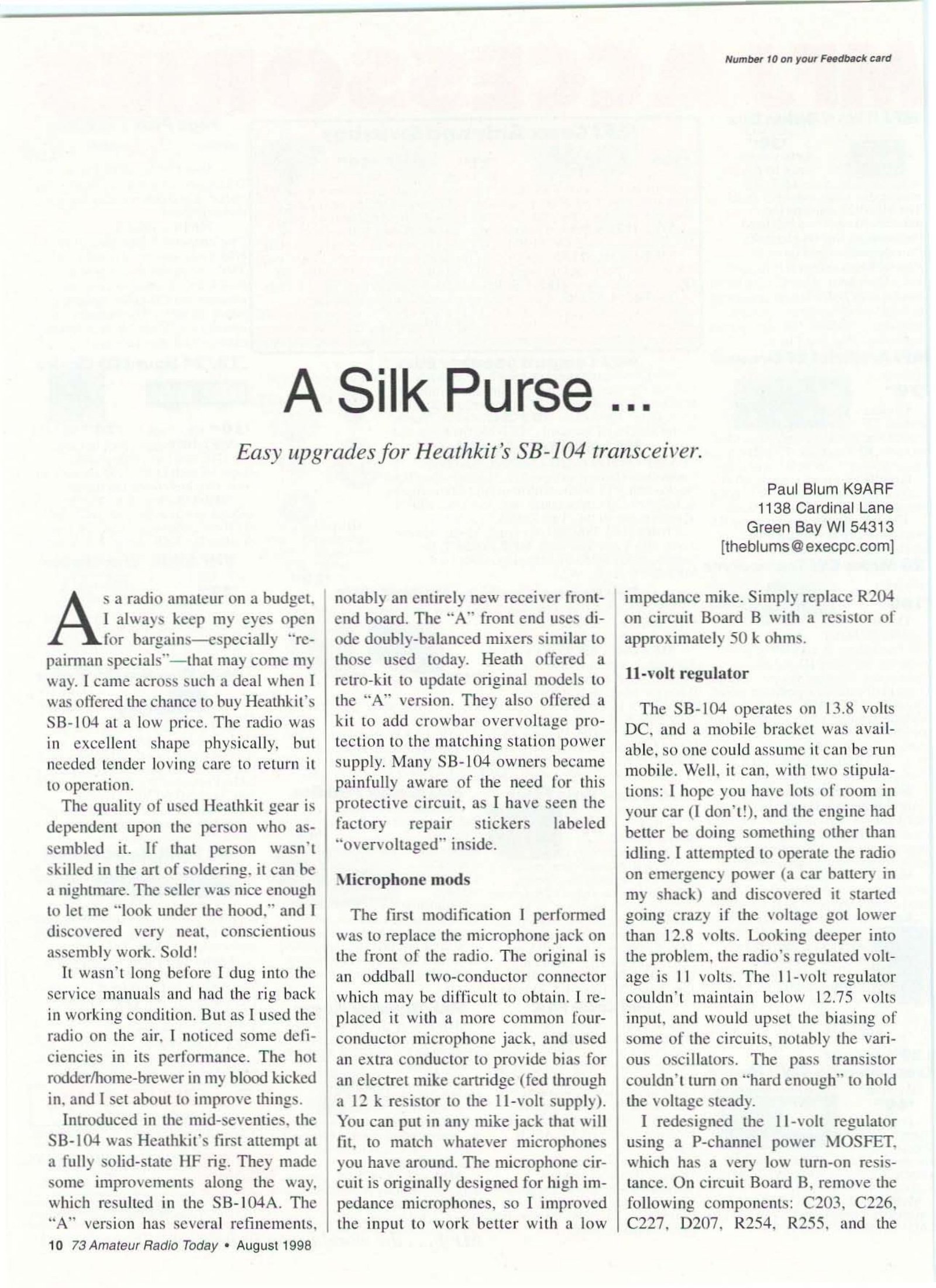
Potentiometers and resistors. The carrier-null control R666 on board E and the S-meter control on board F “tend to open up at the ends”. Both should be replaced with good non-inductive trimmers. Later SB-104As used film resistors. The early carbon-composition resistors drift with age and moisture and should be measured when suspect.
Receiver front end and filters. The front-end board G is the hardest to align. K5BCQ found toroids off in inductance and filters off in frequency by up to 2 MHz. On one factory-aligned SB-104A board the 10-metre passbands peaked 9 dB below the others, until two turns were removed from an over-wound toroid. His measurements of the SSB filter itself (Heath 404-283) show ripple from 2.5 dB on a good example to 8 dB on a poor one. The balanced-mixer diodes are hot-carrier types and should be replaced as a matched quad, never with 1N914s.
S-meter. The S-meter is fed through a 4.7-volt zener, ZD502, which compresses its range. Heath’s own bulletin SB-104-84 (November 1979) replaced it with a forward-biased diode “only if the customer specifically complains”. K9ARF measured less than 20 dB between S1 and full scale before replacing the zener with two series diodes. K5BCQ recommends a zener of about 1.5–2 volts or the two-diode fix.
5.7 Modifications
The SB-104 attracted more published modifications than most Heath rigs, mostly aimed at the receiver’s strong-signal behaviour.
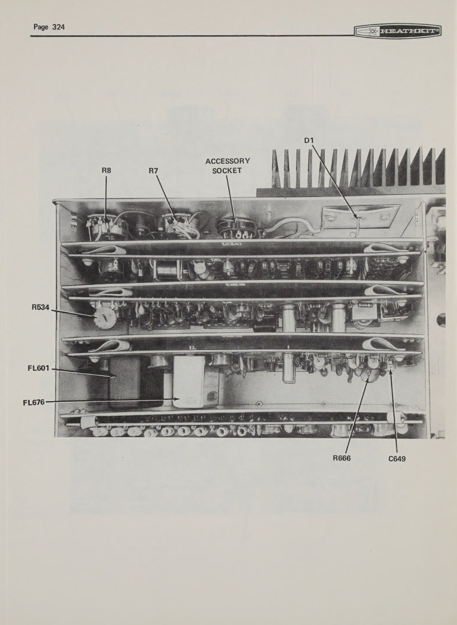
Tashner, 1981. Richard Tashner N2EO’s “Improved receiver performance for the Heathkit SB-104A” in Ham Radio (April 1981, pp. 78–81) was developed “over a two-year period”. Its changes were:
- replace the front end’s band-switching diodes with Motorola MPN3401 PIN diodes;
- replace both discrete mixers on board G with Mini-Circuits SBL-1 double-balanced mixers, and raise the current in the 2N5109 post-mixer amplifier to about 100 mA;
- rewire the noise blanker so that it leaves the signal path when switched off;
- install a Fox Tango 33H2.1 crystal filter on board E and move the original Heath filter onto the chassis, in cascade with it, for better skirt selectivity;
- make fourteen resistor and transistor changes on board F for strong-signal handling, lower hiss and slower AGC release;
- increase HFO injection on board D;
- adopt the tab transistor for Q207, and the 0.68 µF ALC capacitor change “suggested by Heathkit”.
After the modifications he could tune within 18–20 kHz of local signals 60 dB over S9 with only slight desensitisation. Side by side with “a top-of-the-line Japanese transceiver” the SB-104A had less hiss and a sharper cut-off beyond 2.8 kHz (Ham Radio, April 1981). K5BCQ lists it as April 1985; the issue is April 1981.
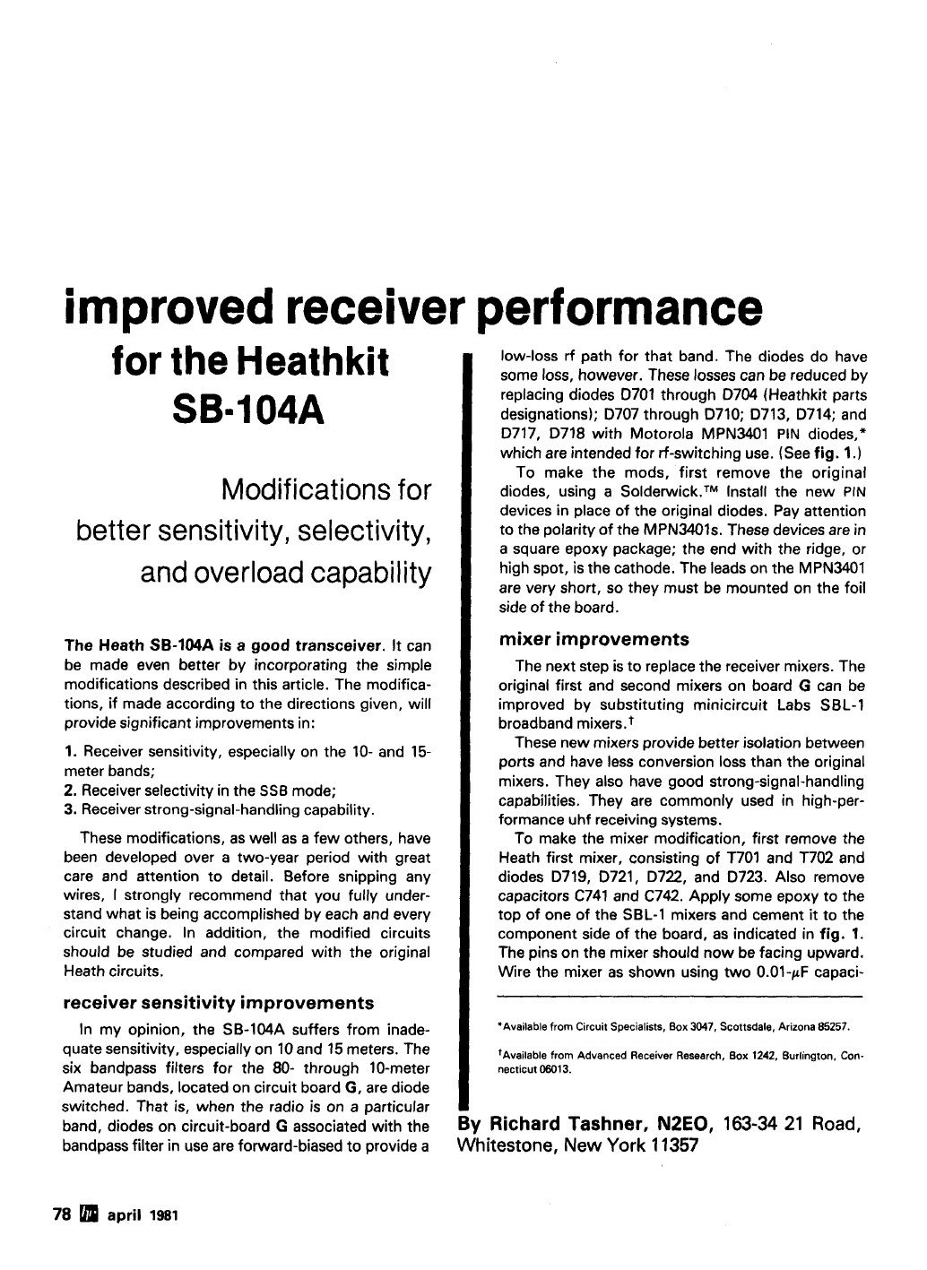
K9ARF, 1998. Paul Blum’s “A Silk Purse …” in 73 Amateur Radio Today (August 1998) is a restorer’s set of changes:
- a four-conductor microphone jack in place of the “oddball” two-pin one, with bias for an electret microphone;
- the MOSFET 11-volt regulator described above;
- the two-diode S-meter fix;
- a three-part hold-off that stops the AGC “pop” on unkeying;
- a relay-switched 20 dB receive attenuator on the unused noise-blanker switch;
- an INRAD (Fox Tango) filter;
- a second crystal filter with a small FET amplifier, which he found worked so well that he never switched it out.
He found the noise blanker “a major cause” of poor dynamic range and simply unplugged it (73, August 1998, pp. 10–12).
Others. K5BCQ lists two QST articles that were not consulted for this dive: Harlan Bercovici W0MYN, “Improving the SB-104A/SB-644A” (August 1979), and David Palmer W6PHF, “Refining the SB-104” (March 1982). WB4KDI’s HW-104 page cites CQ, August 1975, pp. 28–32, 68, 69 and 73, for its block diagrams; that article was not consulted either. K5BCQ also recommends a plug-in relay (the Potter & Brumfield R10 series) in place of the original T/R relay if it gives trouble. Two further options are relay switching of the front-end filters instead of diodes, and a proper diplexer on the mixer IF ports.
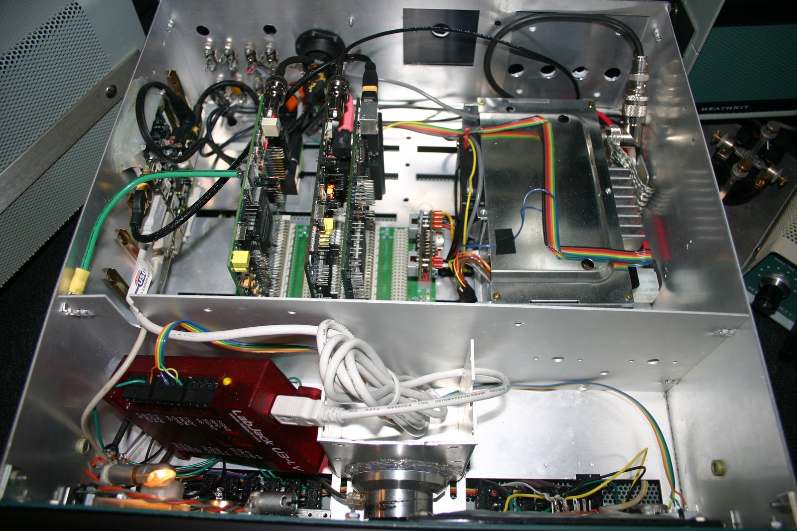
Gutted and reused. At least one SB-104 cabinet and chassis has been emptied to house a modern HPSDR software-defined radio. Its front panel and VFO knob are kept, and the original boards are gone. It is a conversion, not a restoration, and is shown here for completeness.
5.8 Cosmetics
The cabinet is a two-piece wraparound shell held by side rails, #10 screws and flat washers. Heath’s service department found that keeping the rails and washers together during reassembly was awkward enough to need a bulletin. SB-104-29 (March 1976) recommends cutting a spring (Heath 258-53) in half and slipping it over each screw. The panel is screened and the display window is a red filter. Both should be cleaned with a mild detergent and water rather than solvent. The knobs use Allen set screws, and the large tuning knob and its spinner use two.
5.9 Parts, today
The scarce parts are the ones that make the rig what it is: the MFC6030 regulators, the display tubes and their driver ICs, the exact final and driver transistors, the crystal filters, and the board-to-board extender. K5BCQ, writing in 2002, pointed to Athena Electronics for the DM8880 display drivers and to reproduction extender cards discussed on the HEATH mailing list. Availability changes, and those sources may no longer apply. Modern substitutes exist for most other devices, but WB4KDI warns that the MFC6030 and the RF power devices “do not have drop in replacements”. The HEATH reflector archive at puck.nether.net, which holds W7LPF’s original bulletin posts, remains the deepest single store of owner experience (HEATH list, 1997).
Sources
- Heath Company, SB-104 service bulletins SB-104-1 to SB-104-103 (1975–1989), W7LPF transcription. Nostalgic Kits Central · HEATH list, part one, October 1997 · part seven and final, November 1997
- Heath Company. Modification Kit for the SB-104 Single Sideband Transceiver, Model SBM-104-1, 597-1576. Internet Archive
- Heath Company. Heathkit Operation Manual, Single Sideband Transceiver Model SB-104 (1974). Internet Archive (DLARC)
- K5BCQ. “Heathkit SB-104, HW-104, SB-104A Transceiver Repair” (updated January 2002). Link
- WB4KDI Engineering Notebook. “Help! I Just Got a SB/HW-104” and the HW-104 board pages. Link · Index
- Tashner, Richard (N2EO). “Improved receiver performance for the Heathkit SB-104A.” Ham Radio, April 1981, pp. 78–81. PDF, World Radio History
- Blum, Paul (K9ARF). “A Silk Purse … Easy upgrades for Heathkit’s SB-104 transceiver.” 73 Amateur Radio Today, August 1998, pp. 10–12. PDF, World Radio History
- Ames, Richard. “SB-104hpsdr.JPG.” Wikimedia Commons, CC BY-SA 3.0. Link
- Heath Company. HP-1144 AC Power Supply Assembly Manual, 595-1599-01 (copyright 1974), specifications. Internet Archive (DLARC)

Comments (0)