SB-301 / SB-401 Station · Volume 2
How It Works
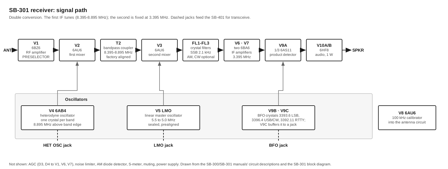
Both units use the frequency scheme that defines the whole early SB line. There are two conversions. The first is crystal-controlled, and it moves any 500 kHz amateur band segment to one fixed window at 8.395–8.895 MHz. The second is tuned by a single linear master oscillator, the LMO, and it moves that window to a fixed intermediate frequency of 3.395 MHz, where a crystal-lattice filter sets the selectivity. The receiver follows that path from the antenna down to audio. The transmitter follows the same path in reverse, from a sideband generated at 3.395 MHz up to the antenna.
The consequence is what makes the station work. The receiver and transmitter need the same three oscillator signals: a heterodyne crystal for the band, the LMO for the position in the band, and a carrier crystal for the sideband. So they can share them. This volume covers the two circuits. Transceive covers the sharing.
2.1 The frequency scheme
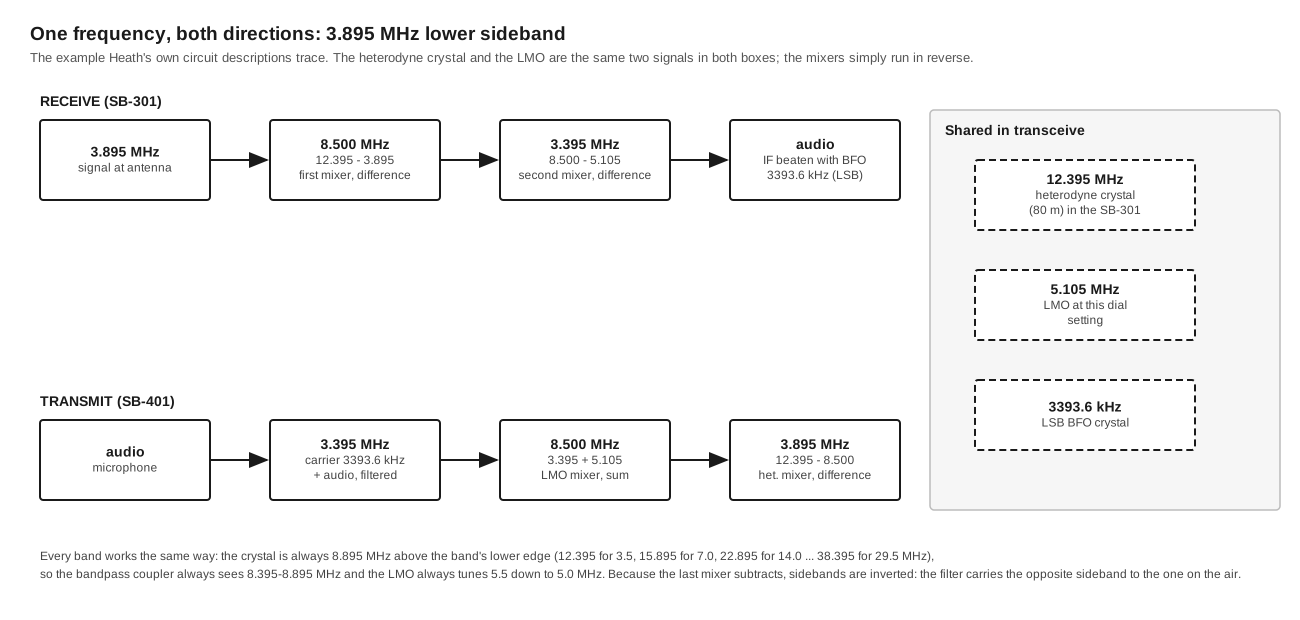
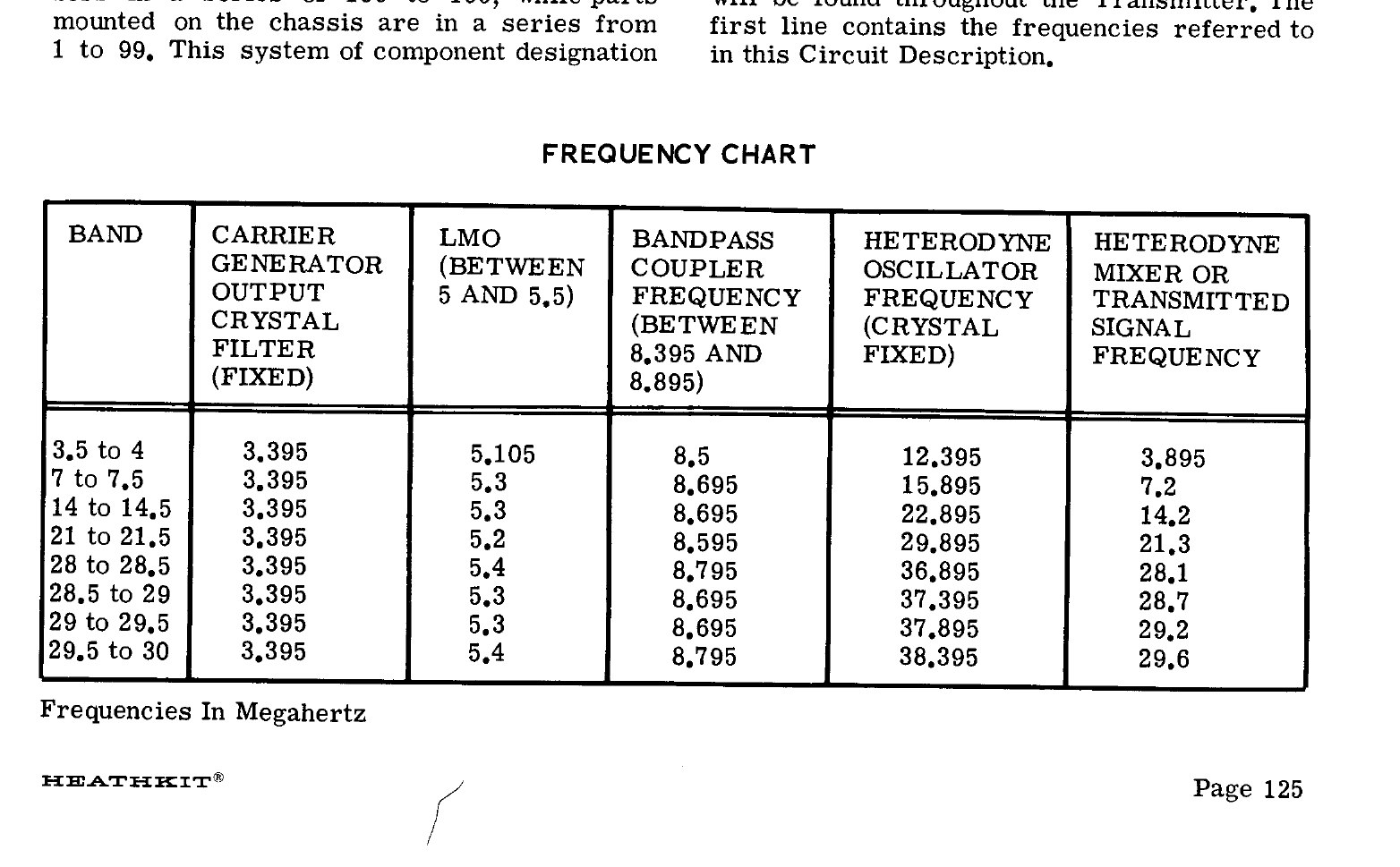
Every heterodyne crystal is exactly 8.895 MHz above the lower edge of its band segment. The first mixer takes the difference between crystal and signal, so the bottom of any band always lands at 8.895 MHz and the top at 8.395 MHz.
Table 1 — The frequency scheme
| Band switch | Receives (MHz) | Heterodyne crystal (MHz) |
|---|---|---|
| 3.5 | 3.5–4.0 | 12.395 |
| 7.0 | 7.0–7.5 | 15.895 |
| 14.0 | 14.0–14.5 | 22.895 |
| 15.0 (SB-301 only) | 15.0–15.5, for WWV | 23.895 |
| 21.0 | 21.0–21.5 | 29.895 |
| 28.0 | 28.0–28.5 | 36.895 |
| 28.5 | 28.5–29.0 | 37.395 |
| 29.0 | 29.0–29.5 | 37.895 |
| 29.5 | 29.5–30.0 | 38.395 |
The LMO then has to tune 5.5 MHz at the low end of each segment and 5.0 MHz at the top, so that 8.895 − 5.5 and 8.395 − 5.0 both come out at 3.395 MHz. Because the LMO covers exactly the same range on every band, one dial calibration serves all nine band positions. The large round dial is marked in kilohertz, one turn covers 100 kHz, and the slide-rule pointer above it counts turns. To read the frequency, add the band-switch figure, the slide-rule reading in hundreds of kilohertz and the dial reading in kilohertz. The manual’s example is band 3.5, pointer between 2 and 3, dial 53: 3.753 MHz (SB-301 manual, p. 67). The SB-100 series transceivers use the same arithmetic, and so does the SB-303 receiver.
The linear in “linear master oscillator” is the point. An ordinary VFO’s frequency is not proportional to the angle of its tuning capacitor, so its dial scale bunches up at one end. The LMO is built and calibrated to tune 100 kHz per shaft revolution, evenly. That is why a mechanical dial with 1 kHz marks can be trusted to within a few hundred hertz after zeroing on the nearest 100 kHz calibrator point. Heath specified 200 Hz visual accuracy and 400 Hz electrical accuracy. The LMO arrived pre-built and pre-aligned in a sealed can, with the frequency-shift slug and one tube socket accessible. Eckweiler states that it was manufactured for Heath by TRW (HOTM #36). The manuals say only that opening it voids the warranty.
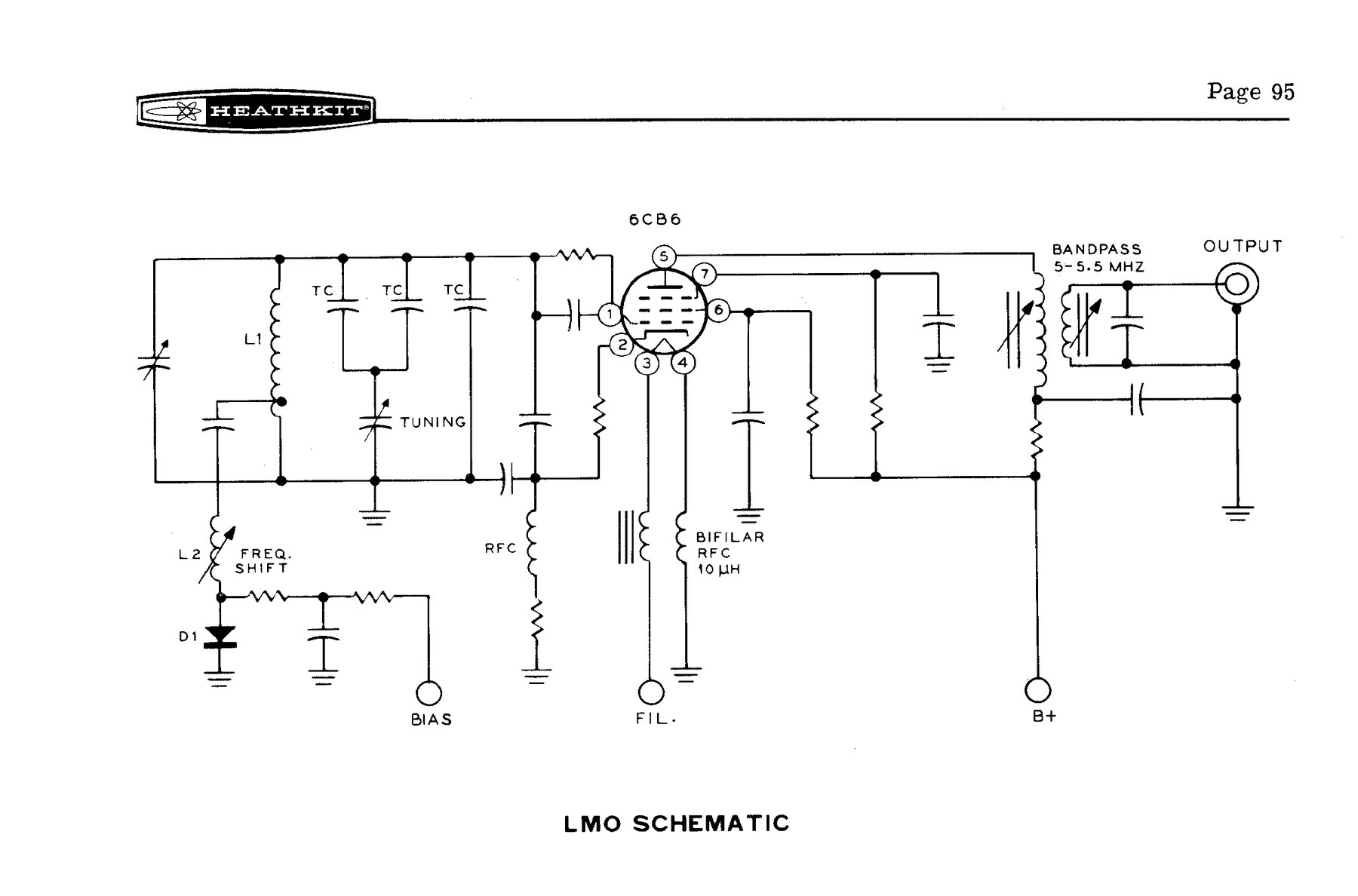
The SB-301’s schematic shows the LMO as an ordinary Hartley-type oscillator (V5) with a tuning capacitor, a set of temperature-compensating capacitors and an output transformer. The SB-300 used a 6AU6 here. Early SB-301s used a 6BZ6, and one version of the specification sheet lists a 6CB6. Eckweiler records all three types across the SB-300/SB-301 production run.
2.1.1 Changing sideband without moving the dial
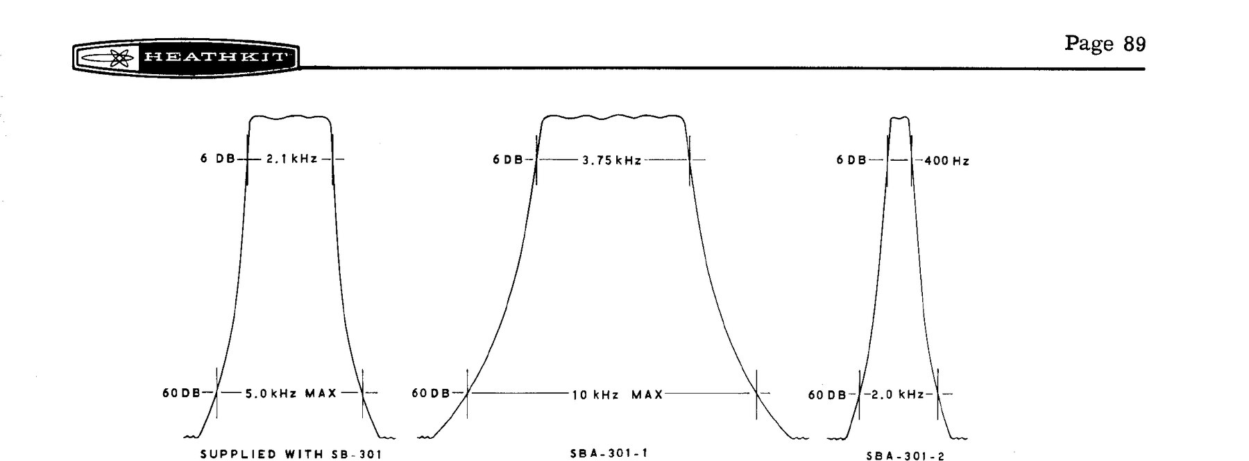
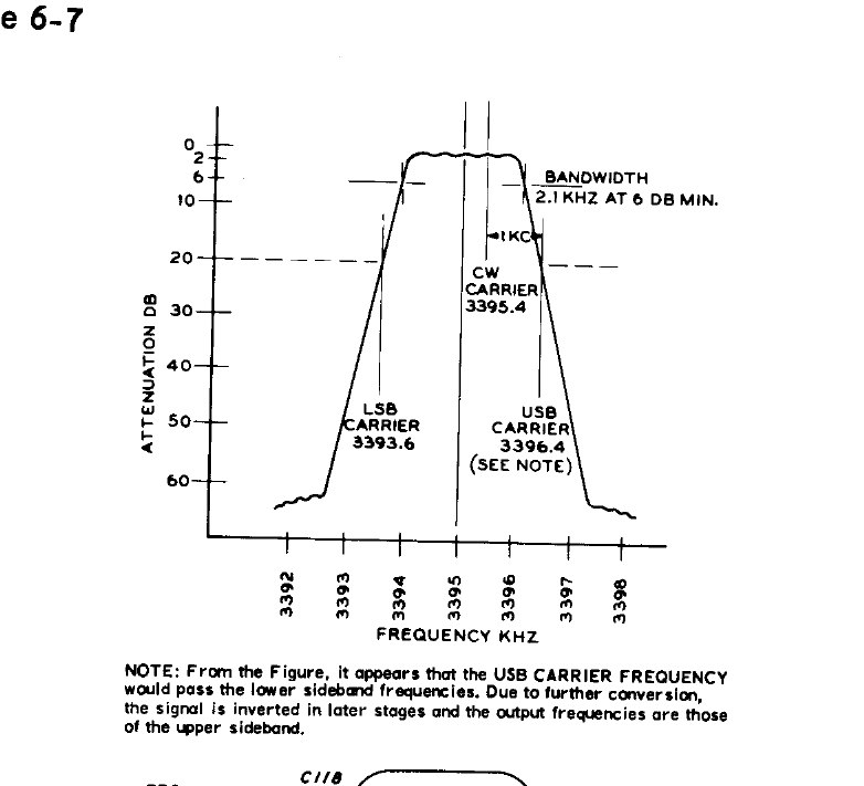
The crystal filter never moves. What moves is the carrier (or BFO) crystal: 3393.6 kHz for lower sideband and 3396.4 kHz for upper, one on each side of the filter’s passband. The filter’s 6 dB points are 3393.95 and 3396.05 kHz. Switching crystals alone would shift the received or transmitted frequency by 2.8 kHz. To prevent that, the mode switch also changes the bias on a switching diode inside the LMO, which shorts out part of the oscillator coil. In the SB-300 manual’s words, +50 V makes the diode “an electrical short” and raises the LMO’s frequency, and −50 V opens it and lowers the frequency (SB-300 manual, p. 7). Worked through, the LMO sits 1.4 kHz above its nominal value on LSB and 1.4 kHz below it on USB and CW. The suppressed carrier therefore lands exactly on the dial reading in both sidebands (Eckweiler, HOTM #43, table 5). The FREQ SHIFT slug on top of the LMO trims the size of the step.
The same trick explains a detail in the transmitter. Because its final mixer takes a difference, the sideband comes out inverted. The SB-401’s crystal filter actually passes the lower sideband of the 3396.4 kHz “USB” carrier, and the Heath manual’s filter figure carries a note to explain the apparent contradiction.
2.2 The SB-301 receiver
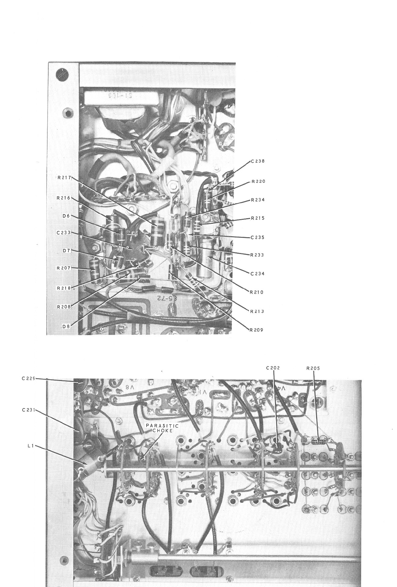
The component numbering follows Heath’s usual convention for the period. Parts numbered 1–99 are on the RF circuit board, 100–199 on the IF board, and 200–299 on the chassis (SB-301 schematic notes). The walk-through below follows the signal.
RF amplifier, V1 (6BZ6). A remote-cutoff pentode between a tuned antenna coil and a tuned plate coil. Both are switched by band-switch wafers and tuned together by the four-section PRESELECTOR capacitor. On 80 metres extra capacitor sections are switched in, and one pair of coils serves both the 14 and 15 MHz positions, and one pair all four 10-metre segments (Eckweiler, HOTM #36). The CONVERTER switch comes before this stage. It selects the HF antenna jack or either of the two VHF converter inputs, and it sends plate and heater power to the converter chosen.
Heterodyne oscillator, V4 (6AB4), and first mixer, V2 (6AU6). V4 is a crystal oscillator with a tuned plate coil for each band. Each coil has a small pickup link, and the band switch routes that link’s output to the HET OSC jack. On the 80-metre example, the 3.895 MHz signal and the 12.395 MHz crystal produce 16.29 MHz and 8.5 MHz in V2. Bandpass coupler T2 passes only 8.395–8.895 MHz, so only the difference goes on (SB-300 manual, pp. 4–6). T2 is aligned at the factory.
Second mixer, V3 (6AU6), and the LMO. The 8.5 MHz signal goes to V3’s grid and the LMO to its cathode. The difference, 3.395 MHz, is taken out through the crystal filter selected by the mode switch. The LMO’s output also goes, through a small capacitor, to the LMO jack on the rear panel.
Crystal filters, FL1–FL3. Only the SSB filter was supplied. The chassis is drilled for the optional AM and CW filters, and the mode switch selects the input and output of each. The SB-301’s filters are physically smaller than the SB-300’s and mount on #4-40 studs in a line, where the SB-300’s used #6-32 studs. The later filters therefore do not drop straight into an SB-300 without new holes, and the older, larger ones will not fit an SB-301 without metalwork (Eckweiler, HOTM #36, rev. A). The CW filter is centred at 3395.4 kHz, not at 3395.0 kHz like the others. That 400 Hz offset comes up again in Transceive.
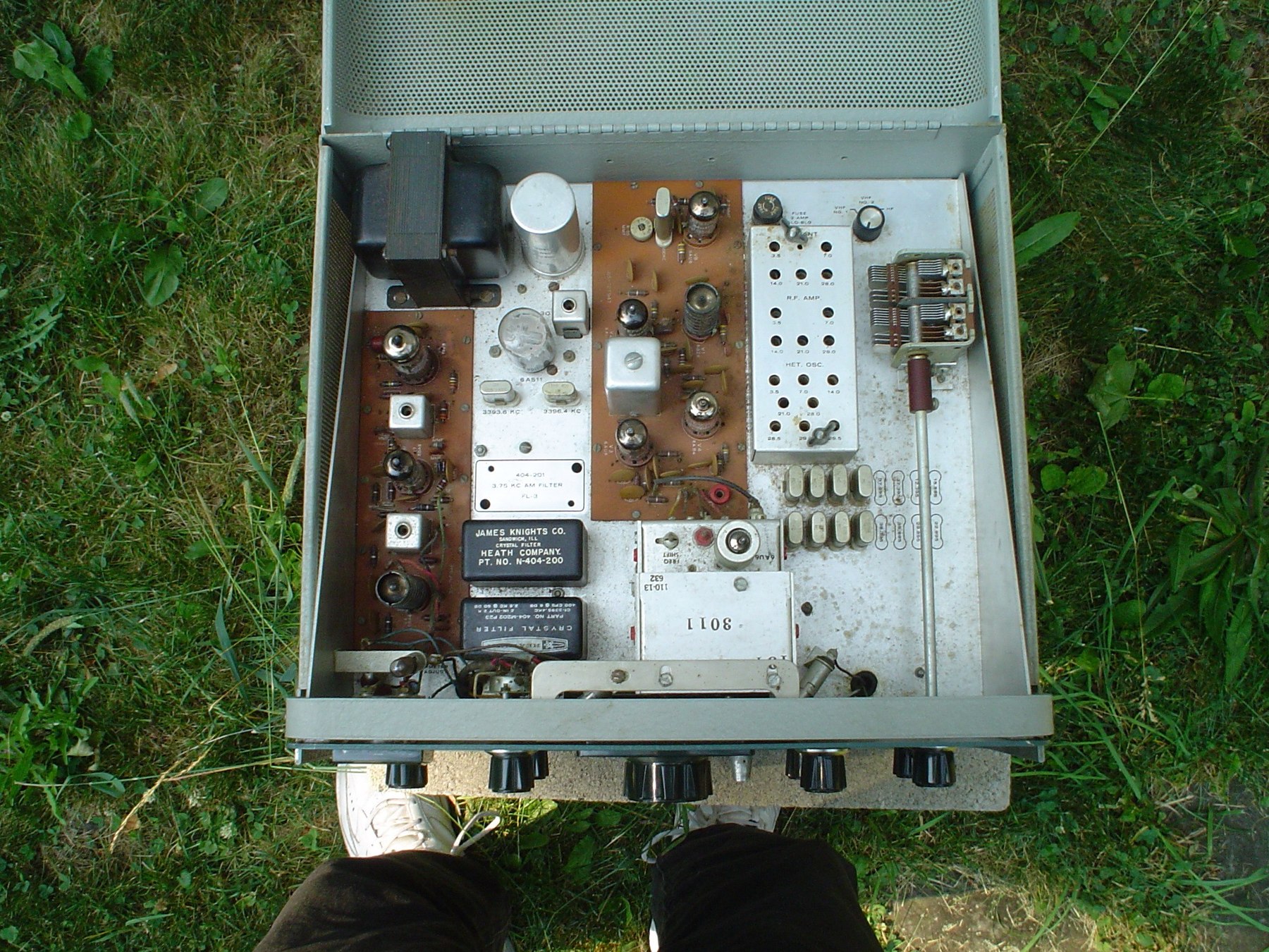
IF amplifiers, V6 and V7 (6BA6). Two high-gain stages at 3.395 MHz, coupled by the IF transformers T3 and T4, which are the only IF adjustments in the receiver. The S-meter sits in a bridge between the stages. Its zero is set on top of the chassis with the antenna disconnected and the RF GAIN fully clockwise (SB-301 manual, p. 89).
AGC. A sample of the IF output is rectified by diodes D3 and D4 into a negative voltage. That voltage shares a line with the bias set by the RF GAIN control, and it reduces the gain of V1, V6 and V7 once it exceeds that bias. The attack is instantaneous. The AGC switch chooses between a fast-release and a slow-release capacitor, or turns the AGC off. The discharge resistor is much larger than the RF GAIN control’s resistance, so the gain setting hardly changes the release time.
Noise limiter (new on the SB-301). A full-wave shunt limiter using two diodes across the second IF circuit. It is self-biased, so its clipping threshold follows the signal level. It is switched on by pulling the AF GAIN knob. Eckweiler found it effective only in some conditions and “much less effective than a noise blanker”. The manual itself warns that it clips and distorts strong signals.
Product detector, BFO and BFO amplifier, V9 (6AS11). A three-section Compactron. V9A is the product detector. V9B is a crystal oscillator on 3393.6 kHz (LSB), 3396.4 kHz (USB, CW and AM) or 3392.110 kHz (RTTY), selected by the mode switch. V9C is a pentode amplifier that drives the BFO jack for the transmitter. It is switched off in the RTTY position, as the manual explains, “to prevent accidental transceiving, as the audio bandpass is unsuitable for transmission” (SB-301 manual, p. 90). The RTTY crystal places the standard 2125 and 2975 Hz teletype tones in the middle of the SSB filter.
AM detection. In the AM position the BFO is turned off, and a 1N191 germanium diode detects the IF signal instead. If the optional AM filter is not fitted, the manual recommends receiving AM in either SSB position with the carrier zero-beaten, the “exalted carrier” method. A Heath News and Views modification put a 470 kΩ resistor across the detector diode to improve AM audio (Eckweiler, HOTM #36).
Audio, V10 (6HF8). The triode section is the first audio stage and the pentode is the output stage. The output transformer has an 8 Ω speaker winding and a 500 Ω winding, which feeds the headphone jack and the ANTI-VOX output to the transmitter. Negative feedback from the secondary to the first stage’s cathode holds distortion to Heath’s 8 per cent at 1 watt.
Crystal calibrator, V8 (6AU6). A 100 kHz oscillator coupled into the receiver’s input in the CAL position of the FUNCTION switch. It is set against WWV with a trimmer on the RF board. On the SB-301 the WWV check can be made on the receiver itself, using the 15 MHz position. Zero beat cannot be heard in the CW position, because the narrow filter removes it, or in AM, where there is no BFO.
Muting. The MUTE jack is grounded in normal use. When the transmitter’s relay opens it, a large negative bias cuts off V1, V2, V6, V7, the audio output V10B and any converter stages. The FUNCTION switch must then be in STBY. In OPR and CAL the receiver grounds the line itself and cannot be muted.
Power supply. A transformer supply with silicon rectifiers. A full-wave rectifier and a four-section filter capacitor, C233, give about 150 V B+. A separate half-wave rectifier gives a negative supply of about 60 V for bias, muting and the LMO diode. The primary can be wired for 120 V or 240 V. The receiver draws 50 W.
2.3 The SB-401 transmitter
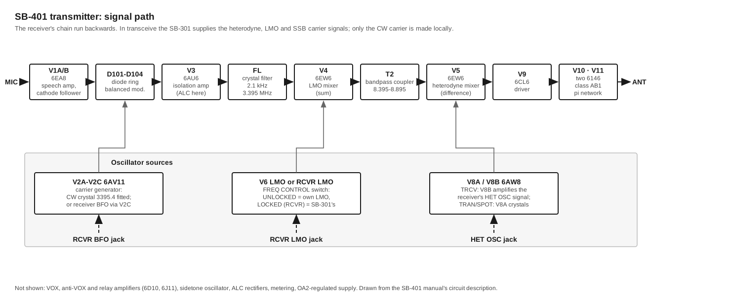
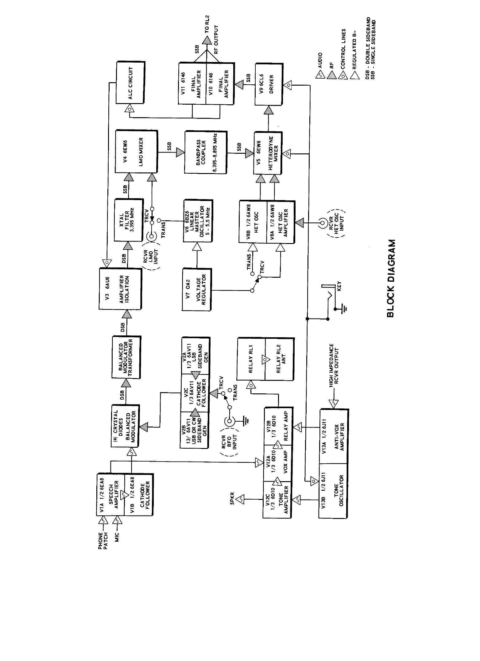
The transmitter’s numbering is organised differently. Parts on the chassis are numbered 1–99, the carrier-generator board 100–199, the mixer-bandpass board 200–299, and so on. Eckweiler notes that most designations changed between the SB-400 and the SB-401 even where the values did not (HOTM #43). The Heath manual divides the circuit into sections. They are followed here in signal order, using the manual’s own 3.895 MHz lower-sideband example.
Speech amplifier and cathode follower, V1 (6EA8). A high-impedance microphone, or the 600 Ω phone-patch input, feeds the pentode section. Its coupling capacitors are chosen to roll off the lows and the highs, and a bypass capacitor keeps RF off the grid. The triode section is a cathode follower that drives the low impedance of the balanced modulator through the MIC LEVEL control. The same audio also goes to the VOX amplifier.
Carrier generator, V2 (6AV11). Another triple-triode Compactron. V2A is a Colpitts crystal oscillator for the LSB crystal, 3393.6 kHz. V2B carries the USB crystal, 3396.4 kHz, or the CW crystal, 3395.4 kHz. V2C is a cathode follower for whichever is running. The SB-401 kit supplies only the CW crystal. The two sideband crystals are part of the SBA-401-1 pack, because in normal transceive use the carrier comes from the receiver’s BFO, through capacitor C127 to the grid of V2C, and the transmitter’s own sideband oscillators are not powered at all (SB-401 manual, pp. 129–130). An internal SIDEBAND AMPLITUDE BALANCE control trims the B+ on V2A so both sidebands come out at the same level.
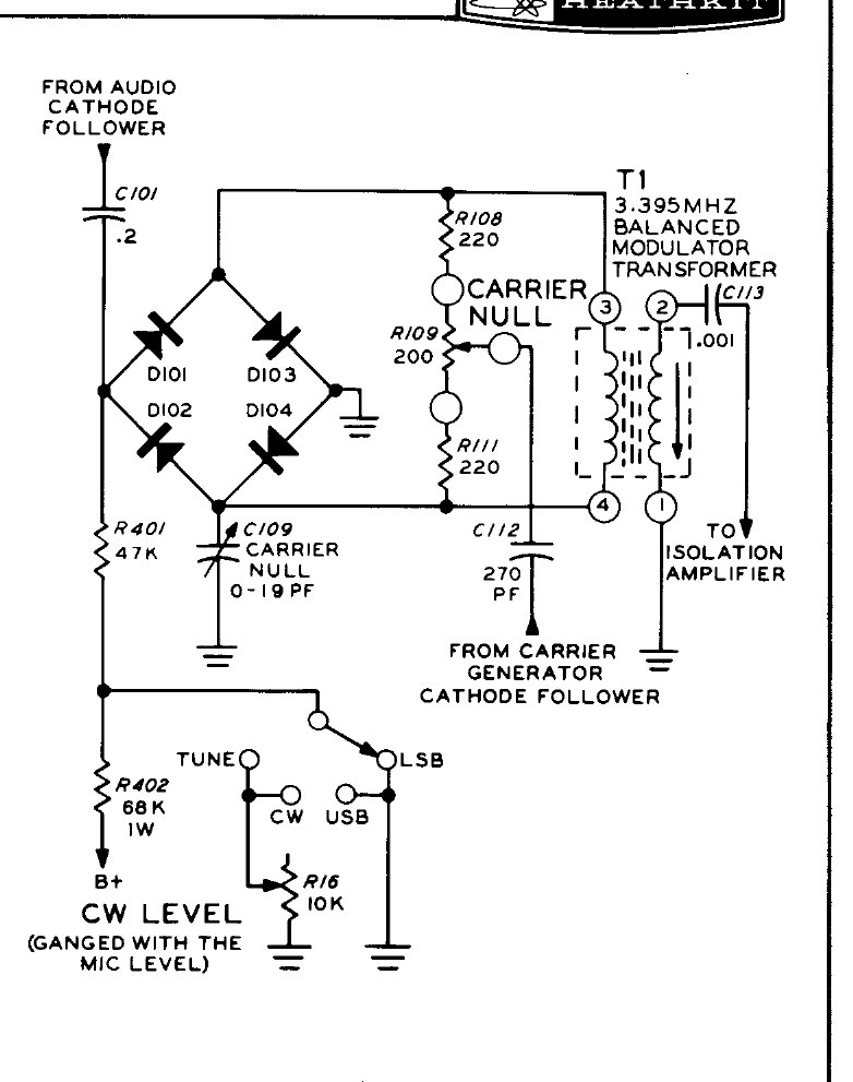
Balanced modulator, D101–D104. A ring of four diodes with the audio across one diagonal and the carrier across the other. The CARRIER NULL potentiometer and a 0–19 pF capacitor balance out the carrier, so only the two sidebands reach transformer T1. For CW, a small DC voltage through a 47 kΩ resistor unbalances the ring on key-down, producing a carrier at 3395.4 kHz. Its level is set by the CW LEVEL control, which is ganged with MIC LEVEL.
Isolation amplifier, V3 (6AU6). This stage keeps the modulator from loading the filter and matches their impedances. It is also where the ALC acts: the ALC voltage sits on its grid. During receive it is biased to cutoff so that nothing leaks through.
Crystal filter. A 2.1 kHz symmetrical lattice filter at 3.395 MHz, the 404-283 part in the SB-401 (the SB-400 used the larger 404-200). It passes one sideband and takes about another 20 dB off whatever carrier the modulator did not null. The manual’s filter figure shows that the “USB” carrier sits on the filter’s upper skirt, so it is the lower sideband that gets through, “due to further conversion, the signal is inverted in later stages” (SB-401 manual, p. 131).
LMO and LMO mixer, V6 and V4 (6EW6). The transmitter’s own LMO, V6 (a 6BZ6, or a 6AU6 in the SB-400), is the same unit as the receiver’s. The LMO mixer takes the filter output on its grid and an LMO signal on its cathode, and passes the sum through bandpass coupler T2, 8.395–8.895 MHz: 3.395 + 5.105 = 8.5 MHz in the example. The FREQ CONTROL switch decides whose LMO it is. In LOCKED (RCVR) it takes the receiver’s, arriving at the RCVR LMO jack, and in UNLOCKED it takes its own. W2JDL found this stage “completely revamped” from the SB-400’s, including a new 21 MHz trap (73, July 1967).
Heterodyne oscillator and amplifier, V8 (6AW8). The triode, V8A, is a crystal oscillator with a crystal socket and plate coil for each band. It runs in the TRAN and SPOT positions of the FUNCTION switch, when the SBA-401-1 crystals are fitted. In TRCV its B+ is removed, and the pentode, V8B, amplifies the heterodyne signal arriving from the receiver instead, using the same plate coils. Either way the result goes to the heterodyne mixer (SB-401 manual, p. 132).
Heterodyne mixer, V5 (6EW6). The 8.5 MHz sideband signal and the 12.395 MHz heterodyne signal meet here. The plate circuit is tuned by one section of the DRIVER capacitor, with coils switched by band, so only the difference, 3.895 MHz, goes on. The unwanted sum is about 17 MHz above it and easily rejected. This subtraction is what inverts the sideband.
Driver, V9 (6CL6). A tuned amplifier whose plate coils are switched by band and tuned by the second DRIVER section. A series-tuned trap in its grid removes an 8.6 MHz product that can otherwise appear near the top of 40 metres. That product comes from the LMO beating with BFO leakage in the mixer. The final’s neutralising circuit also connects here. RF from the final’s plate is fed back to the bottom of the driver plate coil through a small capacitor and a trimmer, which cancels the grid-to-plate capacitance of the 6146s.
Final amplifier, V10 and V11 (two 6146). Two beam tetrodes in parallel in class AB1, biased at about −50 V for a resting plate current of 50 mA for the pair. In standby they are cut off by removing their screen voltage, not by increasing the bias. The output is a pi network: a 250 pF plate tuning capacitor, a three-section loading capacitor (245/245/354 pF) with fixed padding on 40 and 80 metres, a tapped silver-plated coil on a ceramic form, and a separate air-wound coil for 10 metres (Eckweiler, HOTM #43). The FINAL control tunes the pi network and the concentric LOAD control sets the loading into 50–75 Ω.
Automatic level control. When the finals are driven into grid current on voice peaks, the resulting voltage at the grid resistor is rectified and applied to V3’s grid as extra bias, which reduces the gain before the signal splatters. An ALC INPUT jack on the rear lets a linear amplifier’s ALC add to it. Heath rated the ALC at 10 dB of compression for 0.2 mA of final grid current. The meter’s ALC position shows the action, and the operator’s rule is to keep the needle within the ALC zone of the scale.
Metering. A 0–1 mA meter with five positions. GRID is shunted across a fixed resistor in the final grid circuit, normally around 0.1 mA on SSB. PLATE reads the drop across six 10 Ω cathode resistors in parallel, 0–500 mA full scale. ALC reads a bridge in V3’s screen and cathode circuit. HV reads the midpoint of the voltage doubler and is scaled to read the whole supply, 0–1000 V. REL PWR is a rectified sample of the output, set by an internal control.
VOX, anti-VOX and sidetone, V12 (6D10) and V13 (6J11). V12A amplifies microphone audio, or the CW sidetone. A diode rectifies it into a positive voltage on the grid of V12B, the relay amplifier, which is normally biased off. Positive voltage there pulls in the six-pole relay RL1, and the VOX DELAY control sets how long it holds. V13A amplifies audio from the receiver’s ANTI-VOX output and turns it into a negative voltage that cancels what the speaker would otherwise send back through the microphone. V13B is a phase-shift oscillator at about 1 kHz. Keying it drives both the sidetone, amplified by V12C and switched to the station speaker by the relay, and the VOX, which is what gives break-in CW. The relay also switches 120 V AC to an accessory socket for an external antenna relay, applies screen voltage to the finals, operates the internal antenna relay, opens the receiver’s MUTE line and grounds the LINEAR RELAY jack (Eckweiler, HOTM #43).
Power supply. Built in, with silicon rectifiers throughout. A full-wave voltage doubler from a winding of about 275 V AC, with two 125 µF capacitors in series, gives about 720 V at 250 mA for the finals. A half-wave doubler gives about 250 V at 100 mA for most other stages. An OA2 gas regulator (V7) holds 150 V for the LMO and heterodyne oscillator, and a separate winding supplies about −170 V of bias (Eckweiler, HOTM #43; W2JDL, 73, July 1967). The transmitter draws 80 W in standby and 260 W key-down on CW.
2.4 What the SB-303 changes
The SB-303 keeps the architecture and changes the devices. The 1971 catalogue credits it with a dual-gate MOSFET front end, “greater dynamic range with low distortion”, a front-panel RF attenuator, a solid-state LMO with instant warm-up and 100 Hz stability after 10 minutes, a crystal calibrator with 25 kHz as well as 100 kHz markers, and 4 W of audio output. All of this is built on nine plug-in circuit boards (1971 catalogue, p. 76). The heterodyne-oscillator output leaves through two emitter followers, Q201 and Q202, which give a low-impedance drive to the HFO OUT jack (SB-303 manual). That difference in impedance is why an SB-401 needs to be modified before it will transceive with the solid-state receiver. Transceive has the details.
2.5 What the design gives and what it costs
The strengths are the ones the SB line was built on: tuning that is identical and linear on every band, a crystal first conversion that makes stability depend on the LMO alone, and a proper crystal filter at a frequency where it could be made cheaply. In 1967, W2JDL called the receiver’s readout and resettability “outstanding, within a fraction of a kilohertz” and the transmitter’s CW note “clean, chirp free”.
The weaknesses show up on today’s crowded bands. The first IF tunes, so the receiver has no fixed-frequency roofing. It has no noise blanker, and only an ANL. The RF amplifier and the pentode mixers give up strong-signal performance to modern designs. The G3OOU rebuild of an SB-301/SB-310 addressed exactly these points. It fitted 7360 beam-deflection mixers with balanced oscillator injection, added an extra IF stage with AGC on all three, reduced the RF gain, and replaced the detectors and audio with solid-state circuits (G3OOU, “Rebuilt SB-301 Receiver”). Nothing of that kind is needed to enjoy an original set. The Restoration volume deals with getting one working as built.
Sources
- Heath Company. Assembly Manual, SSB Receiver Model SB-301, 595-946-01. W5RKL scan
- Heath Company. Assembly and Operation of the SSB Receiver Model SB-300, circuit description pp. 4–8. W5RKL scan
- Heath Company. Assembly and Operation of the SSB Transmitter Model SB-401, circuit description pp. 124–138. Internet Archive
- Heath Company. Assembly Manual, Solid-State SSB Receiver Model SB-303, 595-1124. Internet Archive
- Heathkit 1971 catalogue, p. 76. World Radio History
- Eckweiler, Bob, AF6C. “Heathkit of the Month #36: SB-301”, rev. A. PDF; “#43: SB-401”. PDF
- Waters, Mort, W2JDL. Reviews of the SB-301 and SB-401. 73 Magazine, June and July 1967. June · July
- G3OOU. “Rebuilt SB-301 Receiver.” Link
- Janis, AB2RA. “SB400 & SB300 Heathkit Twins.” Link
Comments (0)