SB-301 / SB-401 Station · Volume 4
Building the Kits
The SB-301 and SB-401 were the first SB-series kits sold in “sub-packs”. The earlier SB-300 and SB-400 arrived as one carton of loose parts, to be sorted and checked against a single long parts list before building began. The new kits packed the small parts by assembly phase, and each phase opened with its own parts list. Heath’s 1967 catalogue made it a selling point: “Components are packaged separately for each phase of construction … saves you time in selecting components … lets you see your progress more clearly as each phase is completed” (810/67A, p. 82).
It helped. W2JDL started the SB-301 the old way by unpacking and sorting everything. He found the numbered packages only when he tried to check parts against the first list: “Had I read the manual carefully I would have known this. Take warning, do as I say, and not as I do!” (73, June 1967). The receiver took him about 24 hours. The transmitter took 37½ hours, including about two hours of photography, plus about three more hours of alignment (73, July 1967).
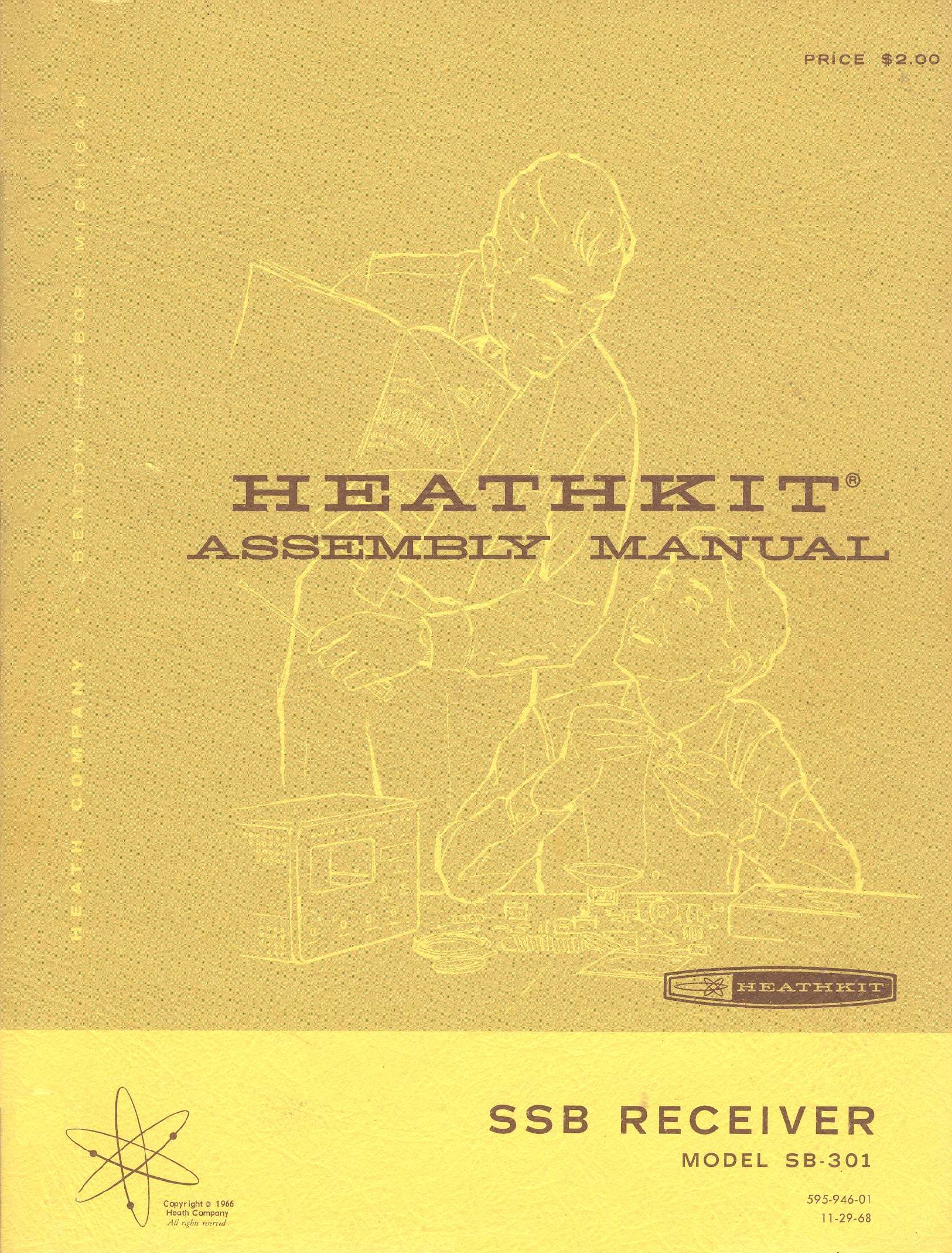
4.1 The SB-301 manual
The manual follows the five sub-packs. Page numbers are the manual’s own, from the 1968 printing (SB-301 manual).
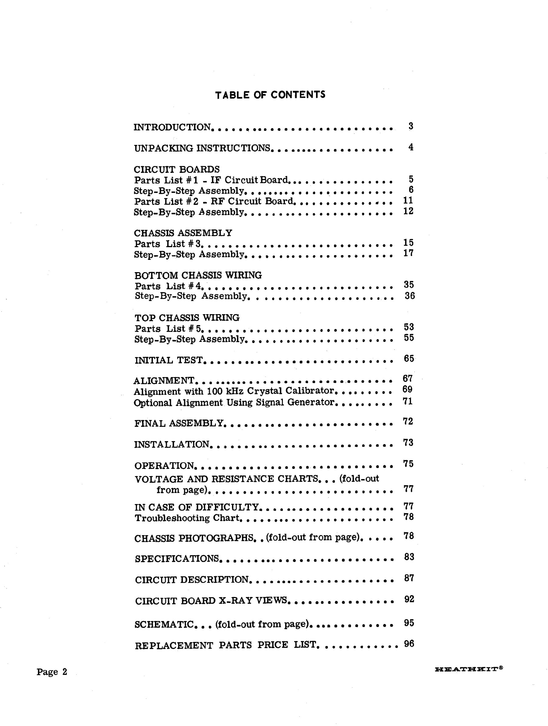
Table 1 — The SB-301 manual
| Section | Pages | What is built |
|---|---|---|
| Introduction, unpacking | 3–4 | Pointer to the separate Kit Builders Guide for tools, soldering and parts identification |
| Circuit boards | 5–14 | Pack 1: the IF board (two 6BA6 IF stages and the 6HF8 audio) and the small noise-limiter board soldered to it. Pack 2: the RF board (RF amplifier, heterodyne oscillator, both mixers, calibrator, and the 8.395–8.895 MHz bandpass coupler) |
| Chassis assembly | 15–34 | Pack 3: the nineteen antenna, RF and heterodyne coils on the chassis top, the partitioned coil cover, transformers, crystal sockets, rear-panel jacks, the two boards and the crystal filters |
| Bottom chassis wiring | 35–52 | Pack 4: the pre-formed wiring harness, the band and mode switches, and most of the small components |
| Top chassis wiring | 53–64 | Pack 5: the LMO and its dial drive, front-panel parts, and mounting the front panel |
| Initial test | 65–66 | Resistance checks before power |
| Alignment | 67–71 | With the built-in calibrator, or with a signal generator |
| Final assembly, installation, operation | 72–76 | Cabinet, station hook-ups, transceive cables, controls |
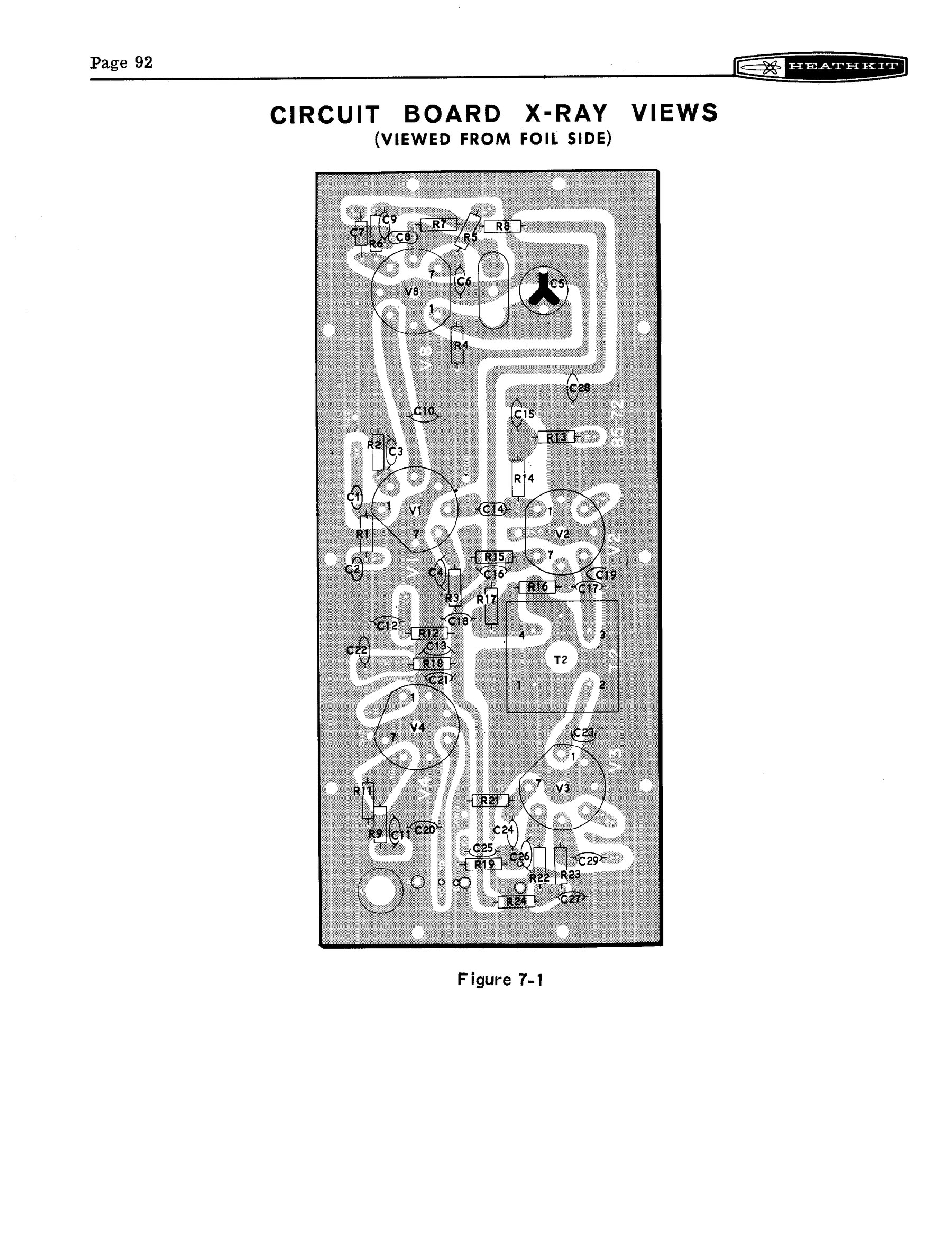
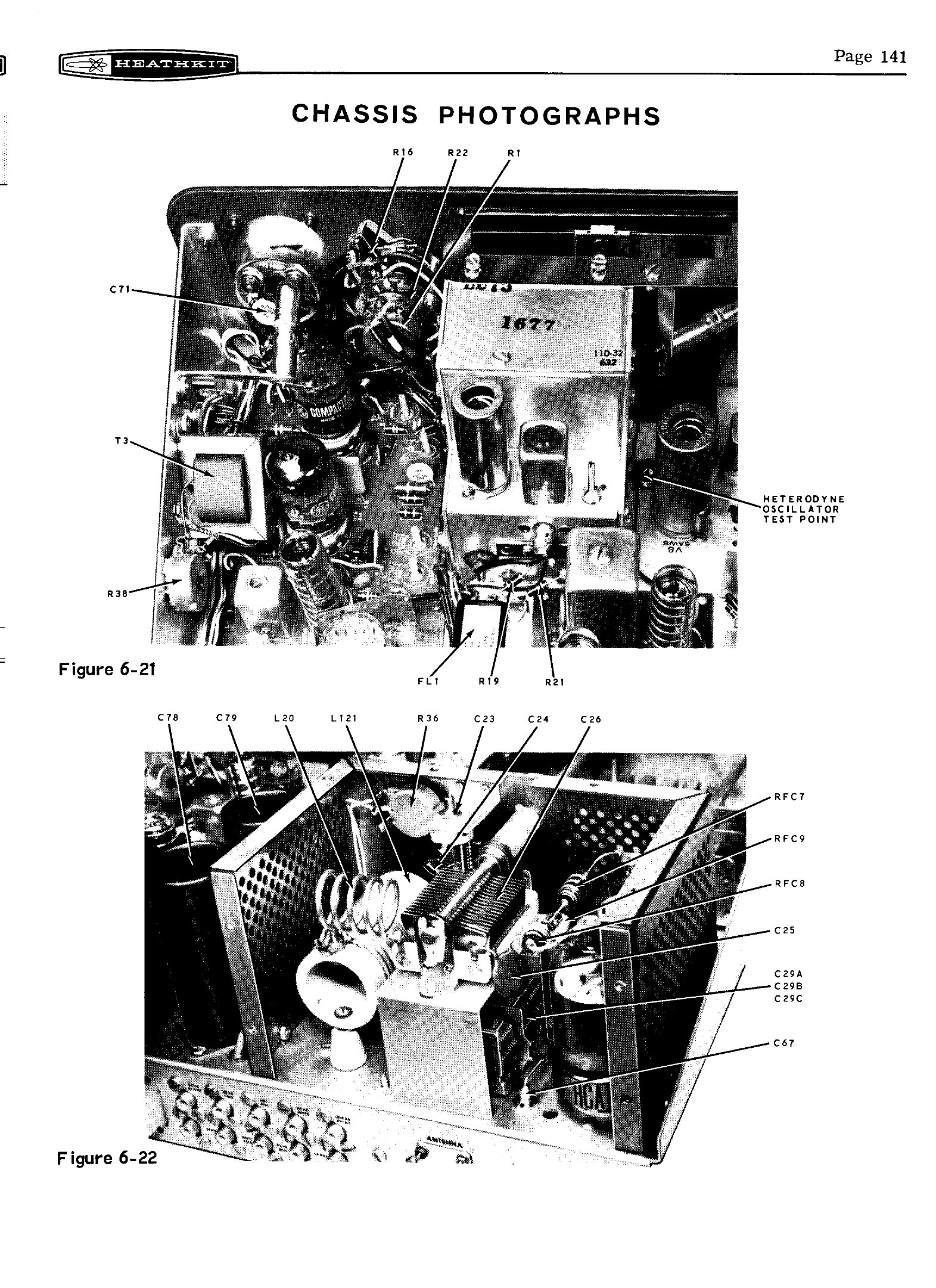
| Reference | 77–96 | Voltage and resistance charts, troubleshooting chart, chassis photographs, specifications, circuit description, X-ray views, schematic, parts price list |
This sequence follows Eckweiler’s account of his 1968 build (HOTM #36). The IF board comes first because it is the simplest, and it gives the builder practice on printed wiring before the more crowded RF board. The chassis is populated from the top, then wired from the bottom, then finished from the top. The mechanical work that decides whether the receiver will be pleasant to use, the LMO and dial drive, comes near the end.
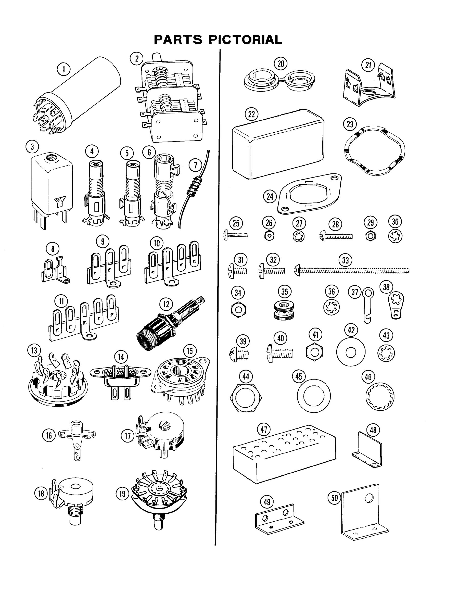
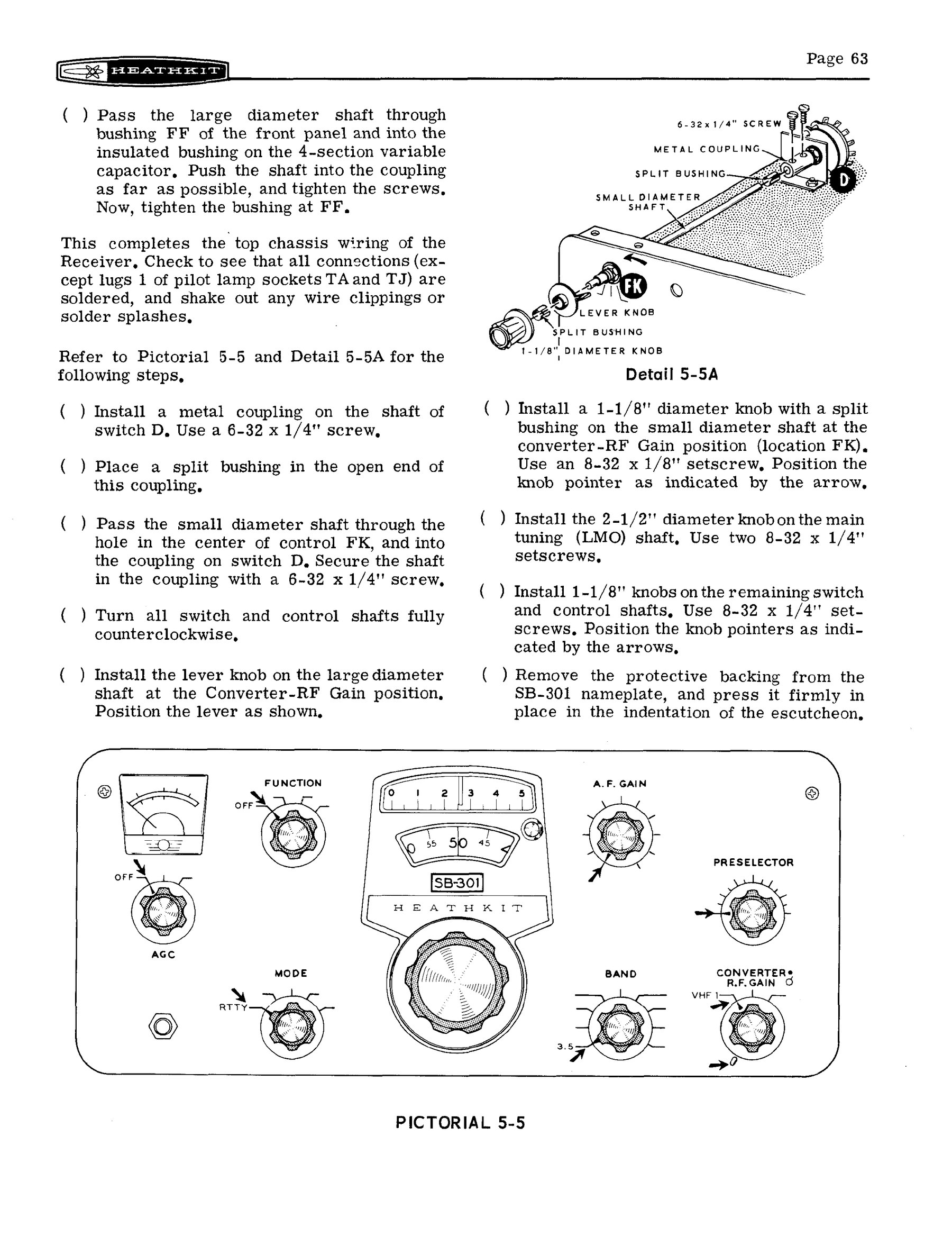
The steps use Heath’s standard layout. Each step has a check-off bracket, ”( )”. Pictorials show each board or chassis area with the components drawn in place, and each group of steps is printed in a “START … CONTINUE … FINISH” column next to the drawing. Components are called out by value and colour code, “470 kΩ (yellow-violet-yellow)”, and not by schematic number. The builder does not need to read the schematic to build the kit. The site’s volume on how a Heath manual works covers the conventions in general.

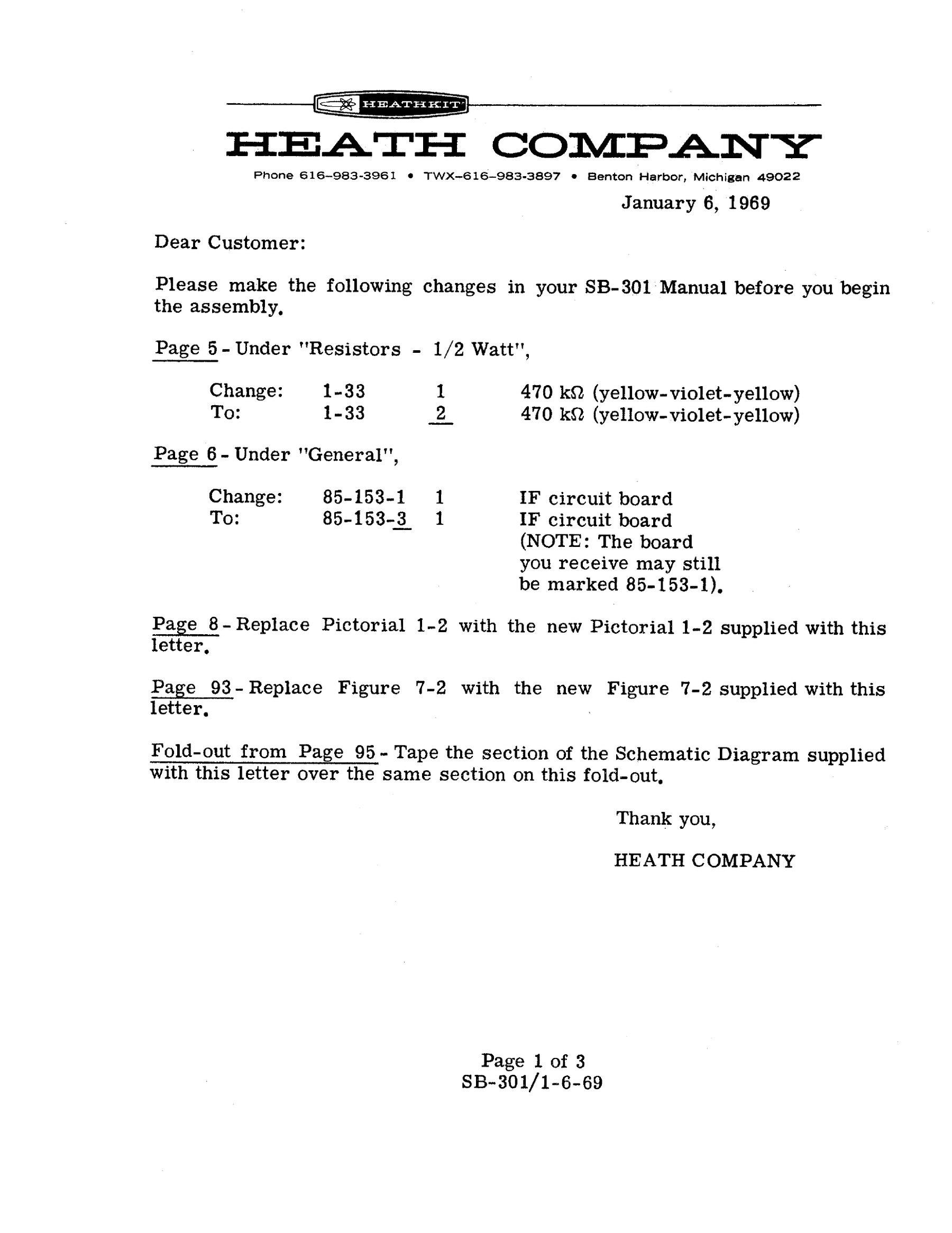
The kit changed during production. A letter from Heath dated 6 January 1969 and filed with this copy of the manual tells the builder to correct the resistor count on page 5 (two 470 kΩ, not one). It also notes that the IF board is now part 85-153-3, though “the board you receive may still be marked 85-153-1”. The letter replaces Pictorial 1-2 and the X-ray view of Figure 7-2, and supplies a corrected section of the schematic “to tape … over the same section on this fold-out”. Letters like this were routine at Heath. Anyone restoring a set should look for the same changes on the boards, because a set built from an unamended manual can differ from its schematic.
4.2 The chassis and the coil cover
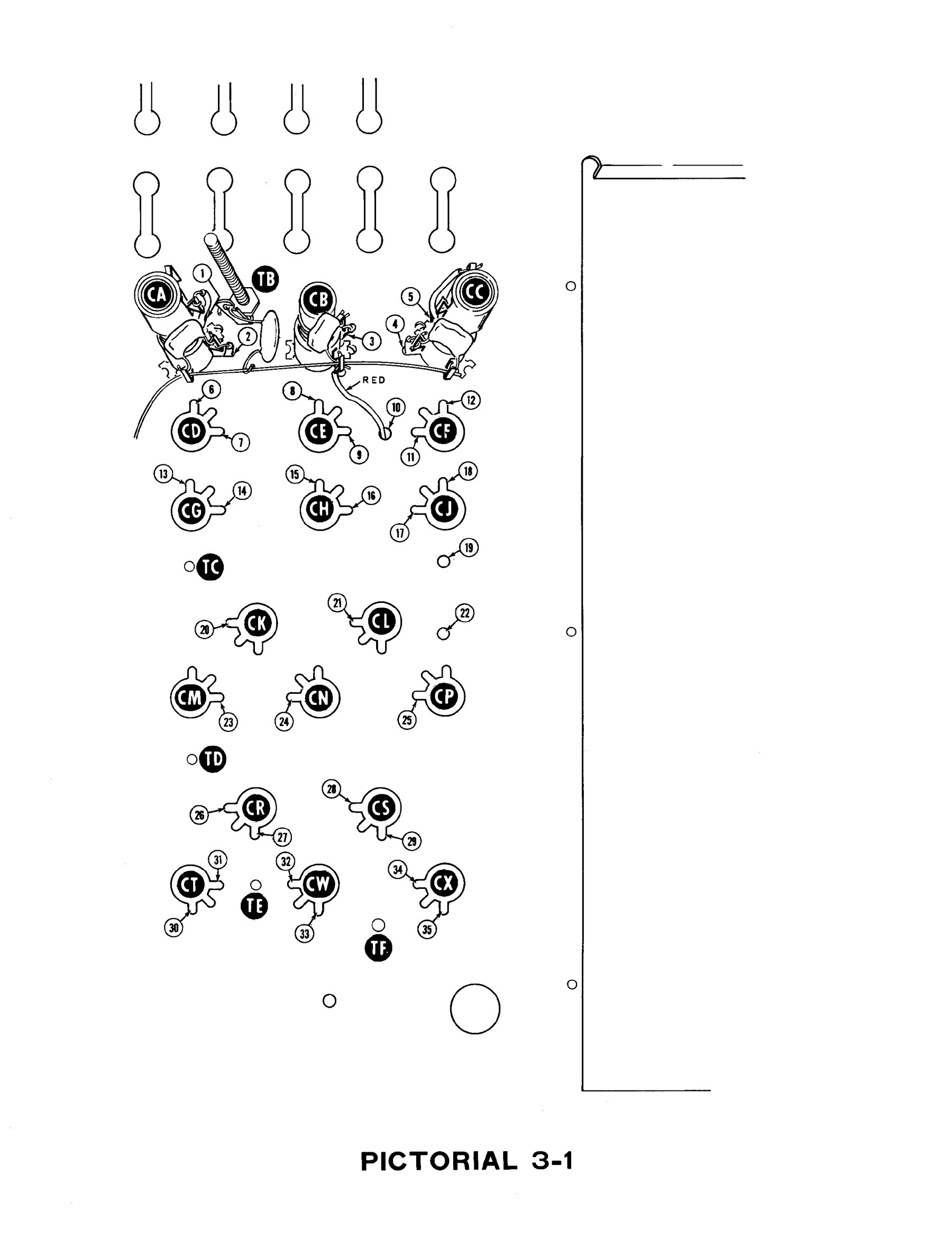
The chassis-assembly section is the longest. Nineteen slug-tuned coils mount on the chassis top in three rows: antenna coils, RF amplifier plate coils and heterodyne oscillator coils. A partitioned cover goes over them early in the job. It protects the coils for the rest of the assembly, and afterwards it serves as a shield and an alignment template. The holes in its top are stencilled with each coil’s band, “ANT”, “R.F. AMP”, “HET. OSC.”, and every slug is adjusted through them. W2JDL used the holes to tell an SB-301 from an SB-300: the pattern shifted to make room for the extra 15 MHz heterodyne coil.
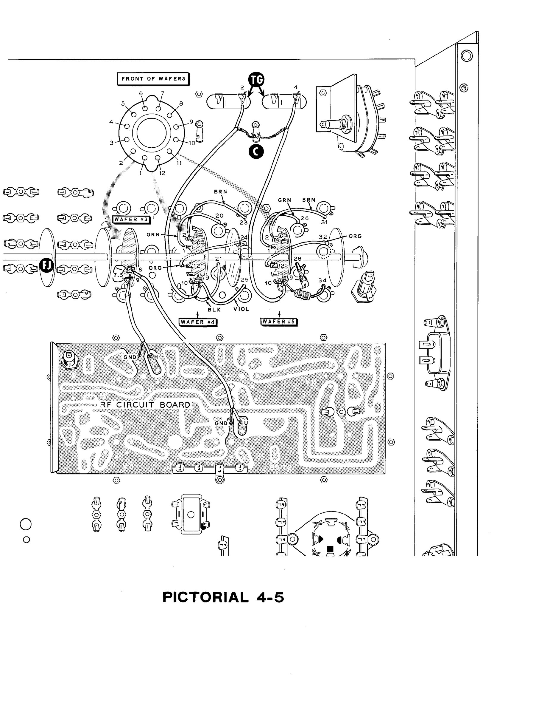
Under the chassis, a pre-formed harness takes most of the long wiring runs. The band switch and mode switch are wired in place as multi-wafer assemblies. The band switch has six wafers, each selecting coils, crystals or capacitor sections. The wafer notation that appears throughout the manual, such as BS1R (band switch, wafer 1, rear), comes from this stage. The two finished circuit boards are bolted down and soldered to the chassis at their ground points. Eckweiler traced a sudden increase in hum decades later to a poor ground where the RF board met the chassis (HOTM #36).
4.3 The dial: the step that matters
Owners have been saying the same thing about the SB dial for fifty years. Built well, it is the best thing about the set. Built badly, it spoils it. Eckweiler wrote that assembling the mechanism “requires a lot of patience … If done right, the dial feels like velvet” and warned used-set buyers to check it first (HOTM #30). W2JDL’s advice to SB-401 builders was the same: “Make every effort to achieve proper alignment of the dial mechanism. Set up right it is as smooth as the expensive spread; if not it shrieks, groans and otherwise suffers.”
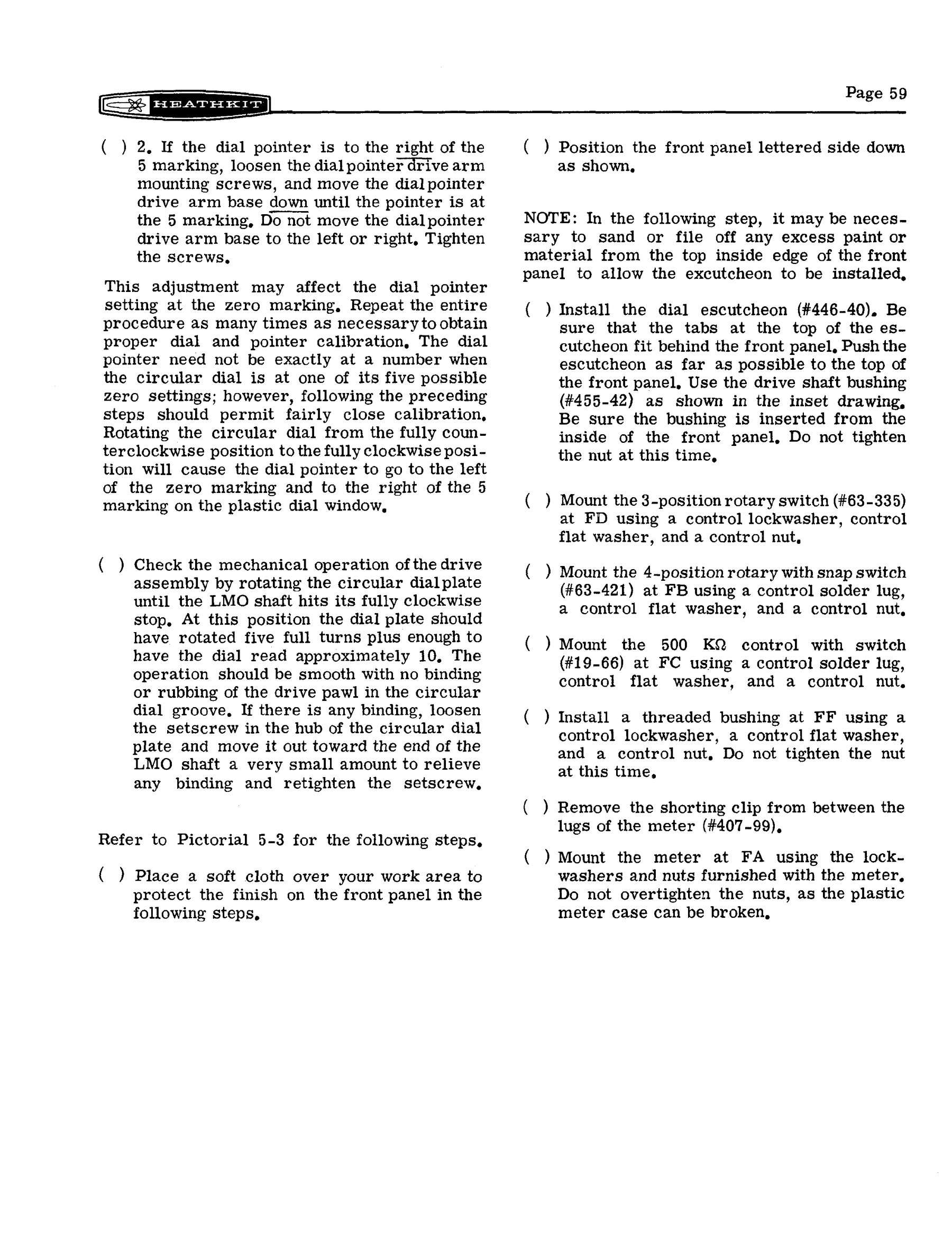
The mechanism has four parts. The LMO shaft carries a round dial plate with a spiral groove on its back. A pawl riding in that groove drives the slide-rule pointer across the window as the dial turns. The tuning knob drives the LMO shaft through a vernier bushing at about 4 to 1. The manual’s procedure sets the pointer to the 0 mark with the LMO at one end of its travel and to the 5 mark at the other, repeating “as many times as necessary”. It then checks that the dial turns five full turns and about ten divisions more from stop to stop, “smooth with no binding or rubbing of the drive pawl in the circular dial groove”. If there is binding, the dial plate is eased a fraction outward along the LMO shaft (SB-301 manual, p. 59). The LMO must also sit square to the front panel. Any misalignment between the LMO shaft and the knob’s bushing shows up as a tight spot once per turn.
4.4 Checks before power
Before power is applied, the builder makes a series of resistance measurements from marked points to chassis. They are taken with the LMO tube removed, one transformer lead left unsoldered, and all controls set to fixed positions. Four of the readings are taken at one phono socket with the FUNCTION switch in each of its positions. The manual warns that the reading across the filter capacitor “will take a few seconds to reach the indicated resistance because of the slow charging rate”. Only then is the lead soldered and the fuse fitted: 2 A slow-blow for 120 V, 1 A for 240 V, and the manual notes that the 1 A fuse is not supplied. The S-meter’s electrical zero is set first, then the calibrator is zeroed against WWV or a broadcast station, then the rest of the alignment follows. The Alignment volume covers it.
4.5 The SB-401 manual
The transmitter follows the same pattern, but it is heavier work. The kit weighed 36 lb shipped, and the finished transmitter weighs 26½ lb. There is a high-voltage supply to build and a shielded final compartment to fit. The manual’s sections are (SB-401 manual):
Table 2 — The transmitter follows the same pattern, but it is heavier work. The kit weighed 36 lb shipped, and the finished transmitter weighs 26½ lb. There is a high-voltage supply to build and a shielded final compartment to fit. The manual's sections are ([SB-401 manual](https://archive.org/details/heathkit-sb401-manual))
| Section | Pages | What is built |
|---|---|---|
| Circuit boards | 5–12 | Pack 1: the mixer-bandpass board (the two 6EW6 mixers and the 8.395–8.895 MHz coupler). Pack 2: the carrier-generator board (speech amplifier, carrier oscillators, balanced modulator, isolation amplifier, VOX, relay and sidetone circuits) |
| Chassis parts mounting | 13–32 | Pack 3: parts under and on top of the chassis, including the driver and heterodyne coils |
| Chassis wiring | 33–72 | Pack 4: wiring top and bottom, the carrier-generator shield and its parts, the transformer, and the band switch |
| Final wiring | 73–86 | Pack 5 and the large parts: dial assembly, front panel, final wiring top and bottom |
| Initial test | 87–89 | Resistance and voltage checks |
| Alignment | 90–102 | Two versions: with the receiver as a transceiver, or with the SBA-401-1 crystals fitted |
| Final assembly, installation and operation | 103–116 | Cabinet, hook-ups, meter, tune-up |
| Reference | 117–148 | Troubleshooting, specifications, circuit description, X-ray views, chassis photographs, schematic, parts list |
Eckweiler noted that the transmitter is “well shielded and assembly includes installing compartment shields, many of which contain components”, which “adds to chassis rigidness, a plus for frequency stability” (HOTM #43). W2JDL’s advice was practical. Lay out the harness leads in their best positions before soldering any of them, twist them where it makes a neater job, and “where the manual specifically instructs you not to shorten leads breaking out of the harness, don’t. Hear and obey!“.
4.6 What went wrong, and what did not
Both reviewers found their sets worked first time. W2JDL reported “Not a single operating difficulty” with the receiver. Eckweiler says the same of his SB-301 (“the receiver worked well right off the bat”). His SB-401 is the one exception he recalls from a lifetime of Heathkits. When he first switched to transmit, “a sizzling noise was heard and sparks were seen in both of the 6146 final tubes”. The antenna relay had been wired wrongly, so the finals were running with no load. The tubes survived, “a few little balls of once molten metal rattling around in each”, and he used them for years (HOTM #43). The lesson for a first power-up is the same today. Connect a dummy load, check the relay wiring against the pictorial, and keep a finger on the power switch.
Heath’s own troubleshooting sections say the same as every Heath manual. “About 90% of the kits that are returned for repair do not function properly due to poor connections and soldering”, so reheating every joint is the first remedy (SB-301 manual, p. 77).
Sources
- Heath Company. Assembly Manual, SSB Receiver Model SB-301, 595-946-01 (copyright 1966; printing of 11-29-68), with change letter of 6 January 1969. W5RKL scan
- Heath Company. Assembly and Operation of the SSB Transmitter Model SB-401. Internet Archive
- Heathkit catalogue 810/67A (copyright 1966), p. 82. World Radio History
- Eckweiler, Bob, AF6C. “Heathkit of the Month #30.” PDF; “#36: SB-301”, rev. A. PDF; “#43: SB-401”. PDF
- Waters, Mort, W2JDL. Reviews of the SB-301 and SB-401, 73 Magazine, June and July 1967. June · July
Comments (0)