SB-301 / SB-401 Station · Volume 5
Alignment and Use
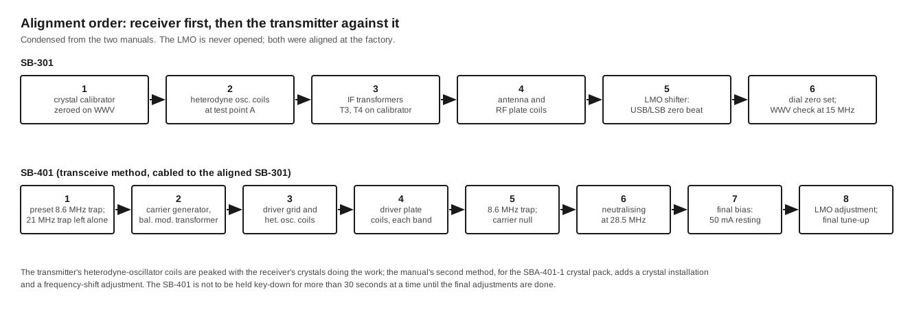
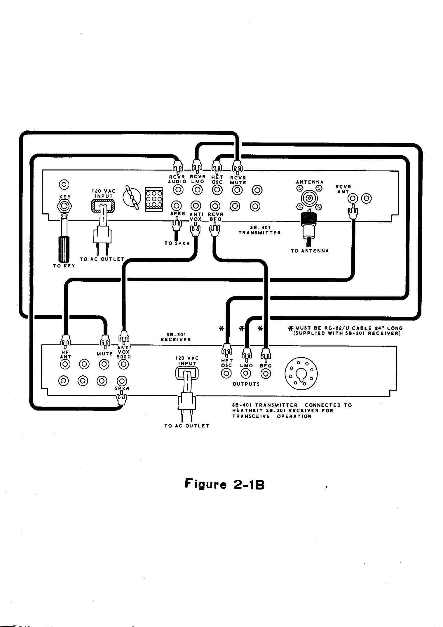
Alignment is done in a fixed order: the receiver first, then the transmitter against the receiver. The SB-301 can be aligned completely with its own 100 kHz calibrator and a VTVM. The SB-401 is aligned with the finished receiver cabled to it as a transceiver, so its heterodyne and driver circuits are peaked on the receiver’s crystals, which are the ones it will actually use. This volume outlines both procedures and their critical points, then covers operating the pair. It summarises the manuals and does not replace them. Anyone realigning a set should follow the manual step by step. The Reference volume lists where free scans can be found.
5.1 Before any of it: the voltages inside
The receiver runs at about 150 V, which is enough to hurt. The transmitter’s supply is a voltage doubler producing about 720 V at 250 mA, and its filter capacitors can hold a charge after the line cord is pulled. Alignment of the SB-401 is done with the cabinet off and the power on. The manual’s instructions to use an insulated screwdriver on the neutralising capacitor and to keep hands out of the final compartment are there for good reason. The Restoration volume covers safe first power-up. Do not align a set that has not been through it.
5.2 Receiver alignment
The equipment needed is an 11 MΩ VTVM and a source of WWV or a broadcast station on a multiple of 100 kHz. A signal generator is optional (SB-301 manual, pp. 67–71).
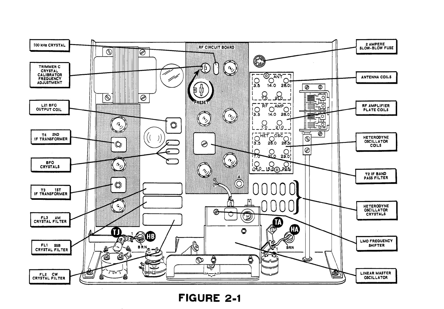
- Calibrator. With the FUNCTION switch at CAL and the receiver’s audio gain turned down, the calibrator’s output is coupled into a second receiver tuned to WWV. The calibrator trimmer, capacitor C on the RF board, is set for zero beat. On an SB-301 the job can be finished later on the receiver itself, using the 15 MHz position.
- Heterodyne oscillator coils. The VTVM goes on test point A, reading negative DC. Each band’s oscillator coil is adjusted to the voltage the manual gives, between 2.4 V and 2.9 V depending on the band. The important instruction is to use the side of the peak where the voltage “will rise and drop in a slow linear fashion”. On the other side the oscillator is close to stopping, and “the voltage will drop rapidly”. An oscillator set on the steep side may fail to start when cold.
- IF transformers. Tune the calibrator signal to one side of zero beat, so that it sits in the middle of the filter where the S-meter reads highest. Then peak T3 and T4.
- Antenna and RF plate coils. On 3.5, 7.0, 14.0, 21.0 and 29.0 MHz, set the PRESELECTOR to the position the manual shows for each band and peak the antenna coil and RF plate coil on the calibrator signal. The other 10-metre positions and the 15 MHz position share coils and are not adjusted separately.
- LMO shifter. At 3.8 MHz, zero-beat the calibrator in USB, switch to LSB without touching the dial, and turn the FREQUENCY SHIFT slug on top of the LMO for exact zero beat. Repeat until both sidebands give zero beat at the same dial setting.
- Dial calibration. Zero-beat at 3.8 MHz, centre the zero-set line, then hold the LMO shaft with a screwdriver through the escutcheon while the round dial is slipped on its hub to read 0. The heterodyne coils are re-peaked for maximum S-meter reading, still on the slow side, and the calibrator is checked against WWV at 15 MHz.
The manual has two firm instructions: “At no time should the slug of coil L21 be adjusted; it was prealigned at the factory”, and the LMO must never be opened, or the warranty is void. A signal-generator version of steps 3 and 4 is given as an alternative. Eckweiler used the calibrator method in 1968, later realigned with a good signal generator, and found no improvement (HOTM #36).
5.3 Transmitter alignment
The SB-401 manual’s main procedure assumes a Heath receiver as a transceiver. Early printings name the SB-301, and later ones the SB-303. A second procedure covers a transmitter fitted with the SBA-401-1 crystal pack (SB-401 manual, pp. 90–102). The equipment is a 50 Ω non-reactive dummy load (Heath’s HN-31 Cantenna is suggested), an 11 MΩ VTVM with an RF probe such as the 309-C, and a key. The manual’s warning comes first: “Do not key the Transmitter for more than 30 seconds at a time until after you have completed the Final Transmitter Adjustments.”
The steps, in outline:
- Traps. Preset the 8.6 MHz trap capacitor by the notch position shown in the manual. The 21 MHz trap is set at the factory: “Do not change the setting of this trap.”
- Carrier generator. With the RF probe on pin E of the carrier-generator board, key the transmitter and peak the balanced-modulator transformer. If there are two peaks, use the one with the slug nearest the top. The manual expects about 1 to 1.5 V. With the mode switch on a sideband and the push-to-talk pressed, alternately adjust the CARRIER NULL control and capacitor for a minimum. Then set the ALC ADJUST control for a zero meter reading.
- Driver grid and heterodyne coils. With the driver tube out and the probe on its grid (pin 2 of V9), peak the driver grid coil and the transmitter’s heterodyne-oscillator coil on each band. The receiver’s band switch is kept at the same setting throughout. About 1.5 V or more is normal.
- Driver plate coils. With the 6CL6 back in and the probe on the finals’ grid line, peak each band’s driver plate coil and then re-peak its grid coil. The manual expects 35 V or more. At 29.0 MHz the extra driver grid coil, the SB-401’s fix for weak drive at the top of 10 metres, is peaked.
- 8.6 MHz trap. Remove the receiver’s 15.895 MHz (40-metre) heterodyne crystal and set the transmitter to 7.0 MHz, CW, SPOT and UNLOCKED. With the driver fully clockwise, tune the trap for minimum output, then replace the crystal.
- Carrier null, finally. On 3.5 MHz, with LEVEL at minimum, null the carrier alternately in USB with the control and in LSB with the capacitor until both sidebands give the same minimum reading. The manual notes that this can be repeated later with the transmitter in its cabinet by watching a receiver’s S-meter.
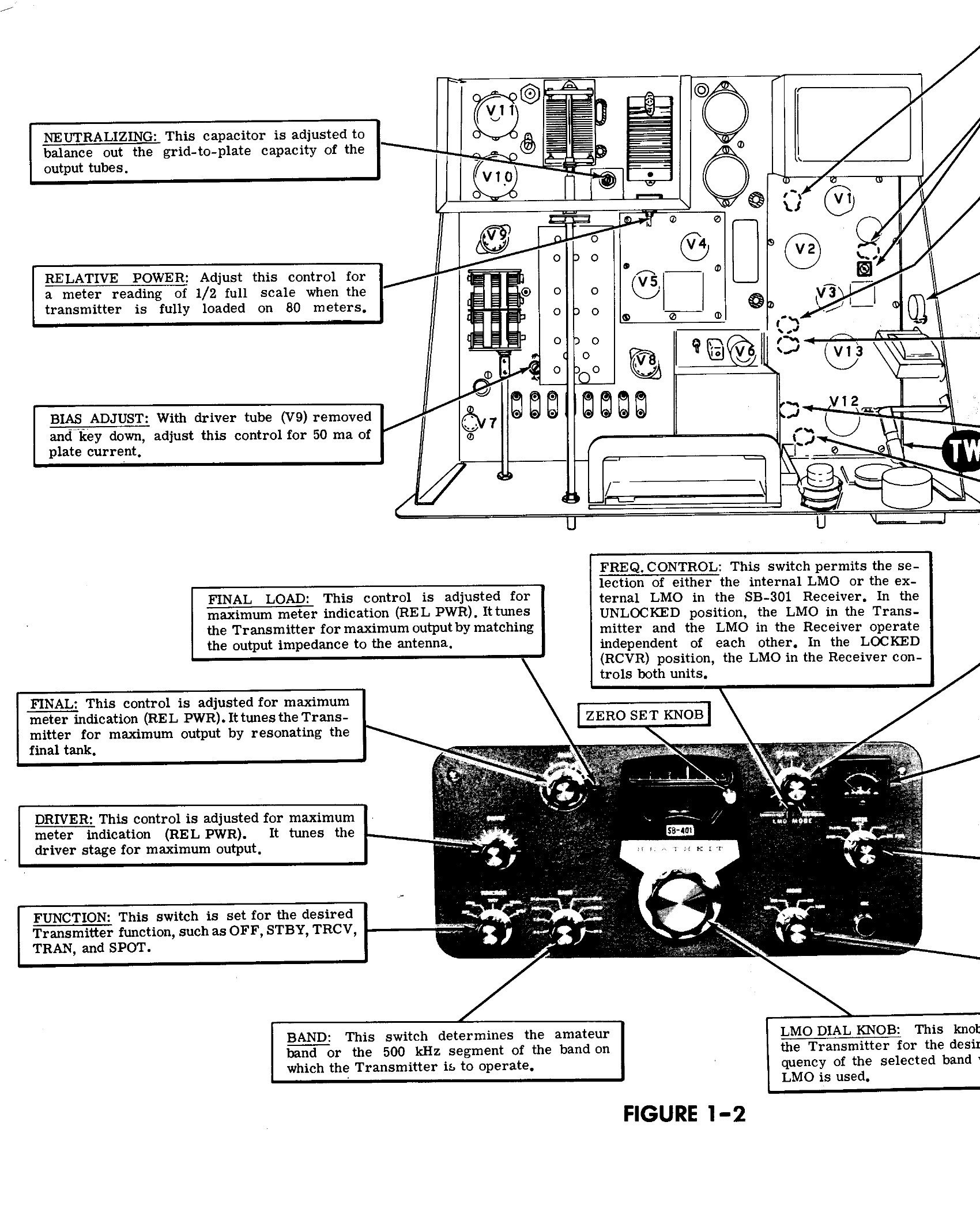
- Neutralising. At 28.5 MHz, connect a temporary 680 Ω resistor to the finals’ screen-grid line as the manual directs. Put the probe on the antenna connector and tune DRIVER and FINAL for maximum. Then adjust the neutralising capacitor with an insulated screwdriver for minimum feedthrough and re-peak FINAL.
- Final bias. With the dummy load connected, the driver tube removed and the meter on PLATE, set BIAS ADJUST for 50 mA with the transmitter at TRAN after a few minutes’ warm-up. That is 25 mA per 6146.
- LMO and final adjustments. Calibrate the transmitter’s own LMO dial against the receiver, then tune up normally. For crystal-pack units, set the transmitter’s FREQ SHIFT slug by ear: talk into the microphone, tune the receiver until the voice sounds natural on one sideband, switch both units to the other sideband, and adjust the slug until the voice sounds natural again.
Heath later published an alternative tune-up, SB-401-8, dated 23 May 1974, which repeats the warning in capitals: “DO NOT HOLD THE TRANSMITTER IN A KEY DOWN CONDITION IN EXCESS OF 30 SECONDS OR DAMAGE COULD RESULT TO THE FINAL AMPLIFIER TUBES”. Companion bulletins give a list of twenty cures for instability, a hum checklist, and RF voltages at every stage for fault-finding (Lutz, SB-401 bulletin index).
5.4 The receiver’s controls
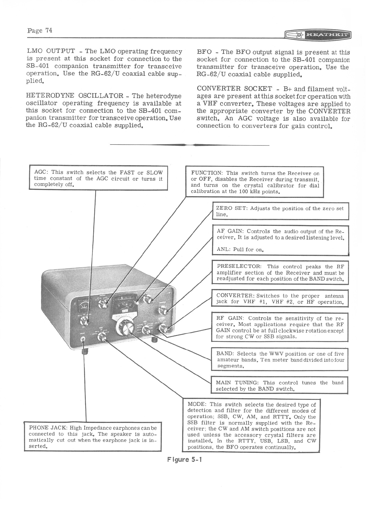
Table 1 — The receiver's controls
| Control | What it does |
|---|---|
| FUNCTION: OFF, STBY, OPR, CAL | Power; standby (muted by the transmitter’s relay); operate (mute line grounded internally); calibrator on |
| AGC: OFF, FAST, SLOW | AGC release time. SLOW for SSB; FAST for AM and CW; OFF for very weak signals |
| AF GAIN (pull: ANL) | Volume; pull the knob out for the noise limiter |
| MODE: RTTY, LSB, USB, CW, AM | Chooses the BFO crystal, the filter and the detector |
| BAND | 3.5, 7.0, 14.0, 15.0 (receive only), 21.0, 28.0, 28.5, 29.0, 29.5 |
| PRESELECTOR | Peaks the RF stage. It must be re-peaked on every band change and after large moves within a band |
| CONVERTER / RF GAIN | Concentric: antenna select (HF, VHF 1, VHF 2) and RF gain |
| ZERO SET | Moves the hairline over the round dial to correct calibration |
| Main tuning | 100 kHz per turn, 1 kHz divisions |
SSB. Set RF GAIN fully clockwise, AF GAIN at about 10 o’clock, AGC SLOW, and the desired sideband. Zero-beat the calibrator at the nearest 100 kHz point and move the ZERO SET hairline onto the dial’s zero. That corrects “for any heterodyne oscillator crystal frequency variation”, so the calibration step has to be repeated after every band change. Peak the preselector and tune. The manual warns against running the AF GAIN at maximum and controlling volume with the RF GAIN, which “will degrade the signal-to-noise performance” (SB-301 manual, pp. 75–76). By convention and in the manuals’ own tune-up tables, LSB is used on 80 and 40 metres and USB on 20 metres and above.
CW. Find the signal in USB, tune it to a 1 kHz note, then switch to CW if the 400 Hz filter is fitted. AM. Use the AM position with the AM filter, or otherwise either sideband position with the carrier zero-beaten. RTTY. Tune until the two tones are balanced at the terminal unit. The manual notes that narrow-shift RTTY is possible in the CW position with the USB and RTTY crystals exchanged.
Read with calibration, the dial reads “within a fraction of a kilohertz”, in W2JDL’s words. Eckweiler found his SB-301 “accurate to within a hundred cycles or so” (HOTM #36).
5.5 The transmitter’s controls and meter
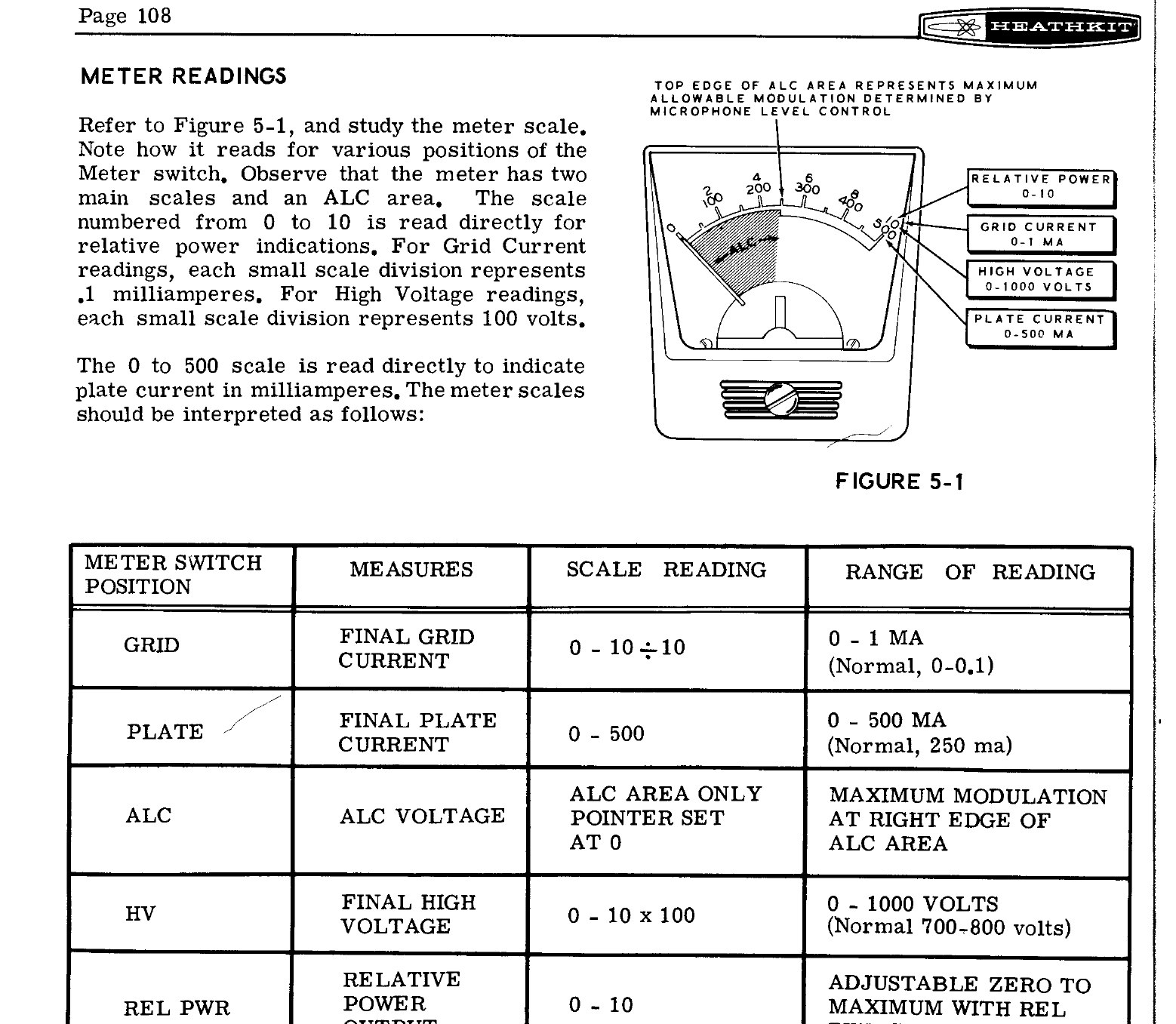
The meter has two main scales and an ALC area. The manual reads them as follows (SB-401 manual, p. 108):
Table 2 — The meter has two main scales and an ALC area. The manual reads them as follows ([SB-401 manual, p. 108](https://archive.org/details/heathkit-sb401-manual))
| METER position | Reads | Normal |
|---|---|---|
| GRID | Final grid current, 0–1 mA | 0 to 0.1 mA on SSB; set to about 0.5 mA during CW tune-up |
| PLATE | Final plate current, 0–500 mA | 250 mA maximum |
| ALC | ALC voltage (pointer set at 0) | Voice peaks up to the right-hand edge of the ALC area |
| HV | Final high voltage, 0–1000 V | 700–800 V |
| REL PWR | Relative output, 0–10 | Set to taste with the REL PWR control |
CW tune-up, from the manual’s lettered chart (p. 114), with the band and dial set and a dummy load or matched antenna connected:
- Put MODE at TUNE and set LEVEL for about 0.5 mA of grid current.
- Peak FINAL for maximum relative power, then peak DRIVER.
- Set LOAD for maximum relative power.
- Repeat until plate current is about 220 mA.
- Change to CW and set LEVEL for about 0.5 mA of grid current with the key closed.
The whole sequence should be done quickly, inside the 30-second key-down limit.
SSB. Tune up as for CW, then change to the desired sideband. With the push-to-talk pressed and no modulation, set ALC ADJUST for zero. It is normal for the meter to read full scale in standby. Set LEVEL so that voice peaks reach the top of the ALC area and no further, because “there is nothing to be gained by modulating so the pointer reaches peaks outside the ALC area, since only distortion and interference to adjacent frequencies will result”. On voice the plate meter will show only about 80–100 mA, because of meter inertia and the peak-to-average ratio of speech. If it reads 150 mA and the scope shows flat-topped peaks, the transmitter is overdriven.
VOX. Set VOX GAIN so normal speech keys the transmitter, and set VOX DELAY for the hold-in time wanted. With the receiver on a strong station at normal volume, advance ANTI-VOX until the speaker no longer trips the relay. On CW the keyed sidetone operates the VOX, which gives break-in keying. Its level in the speaker is set by the internal SIDETONE LEVEL control on the SB-401.
5.6 On the air as a station
Transceive. FUNCTION at TRCV, FREQ CONTROL at LOCKED (RCVR), both band switches the same. The transmitter goes wherever the receiver is tuned. In the manual’s words: “Because all frequency determining stages are in the Receiver, there is no error between transmit and receive frequencies in the transceiver mode of operation.”
Split within a band. FREQ CONTROL at UNLOCKED. The transmitter’s dial now sets the transmit frequency, and the receiver’s dial sets the receive frequency. Heath’s own note on the switch states the difference exactly. For a transmitter aligned as a transceiver, UNLOCKED gives “independent operation of the Receiver and Transmitter on the same band”. For one aligned with the crystal kit, LOCKED gives operation with the SB-300, SB-301 or SB-303, or with an SB-640 external LMO, “independent of band” (SB-401 manual, p. 115).
The FUNCTION switch stays at TRCV whenever the oscillator cables are connected, including on CW and in split. This is the rule that came out of W2JDL’s constant-beat-note discovery, described in Transceive.
SPOT lets the transmitter’s signal be heard in the receiver so that it can be set on frequency before going on the air. The operating chart allows SPOT only with the crystal pack fitted, because in that position the transmitter uses its own heterodyne oscillator.
With a linear. The SB-401 was sold alongside the SB-200 kilowatt amplifier. It keys the linear from the LINEAR RELAY jack, takes the amplifier’s ALC back through ALC INPUT, and switches 120 V AC through its accessory socket to operate an external antenna relay. The manual’s Figure 4-2 shows the full hook-up.
Operators who kept these sets in use report the same things. Eckweiler used the SB-301 as his main receiver into the early 1990s and reported that “stability, CW note and audio quality have always been reported as very good” for the transmitter over more than 25 years (HOTM #43). In 1967, W2JDL found the transmitter’s VOX so smooth that he had to shorten its hold-in to keep up with a quick-fire conversation, and its CW “clean, chirp free”.
Sources
- Heath Company. Assembly Manual, SSB Receiver Model SB-301, 595-946-01, Initial Test, Alignment, Installation and Operation, pp. 65–76. W5RKL scan
- Heath Company. Assembly and Operation of the SSB Transmitter Model SB-401, Alignment, pp. 90–102; Installation and Operation, pp. 105–116. Internet Archive
- Lutz, Joseph W. “Heathkit Service Bulletins: SB-401 (Complete 1966-89).” heath mailing list, 13 June 1998. Archive
- Eckweiler, Bob, AF6C. “Heathkit of the Month #36: SB-301”, rev. A. PDF; “#43: SB-401”. PDF
- Waters, Mort, W2JDL. Reviews of the SB-301 and SB-401, 73 Magazine, June and July 1967. June · July
Comments (0)