SB-301 / SB-401 Station · Volume 6
Restoration and Common Faults
These sets are straightforward to restore. They are well documented, the circuits are conventional, the tubes are mostly common types, and many of the problems owners meet were already known to Heath and covered by factory service bulletins between 1967 and 1980. There are three exceptions: the sealed LMO, a handful of Compactron tubes that are becoming scarce, and the transmitter’s high-voltage supply, which deserves respect. This volume covers all three alongside the routine work.
6.1 Safety
The SB-301 is a mains-powered tube receiver with about 150 V of B+. That is a real shock hazard but a modest one. The SB-401 is different. Its built-in supply is a full-wave voltage doubler producing about 720 V DC at 250 mA for the 6146 plates, and the two 125 µF capacitors behind it can store a lethal charge (Eckweiler, HOTM #43). The same 720 V is on the final amplifier’s plate circuit, the plate choke and the tuning capacitor.
- Work with one hand where possible, on an insulated surface, with the line cord unplugged and in view.
- Discharge the filter capacitors through a suitable resistor and confirm with a meter before touching anything. The manufacturer’s instructions are no substitute for measuring.
- Never defeat the final compartment’s cover while transmitting, and never transmit without a load. Eckweiler’s first power-up, with a miswired antenna relay and no load, left “little balls of once molten metal rattling around in each final tube”.
- Both units take a two-pin line cord at a two-pin rear-panel socket, so the chassis is not grounded through the mains. Fitting a three-wire cord with the chassis properly grounded is standard practice today, but it is a change from the original.
6.2 Buying and first assessment
The dial. Turn it through its whole range by hand before buying. It should feel smooth, “like velvet” in Eckweiler’s phrase. It should turn five full turns plus about ten divisions from stop to stop, and the slide-rule pointer should track from 0 to 5. Roughness is usually a matter of the LMO’s alignment to the panel or the dial plate’s position on its shaft, which the manual shows how to fix (HOTM #30). A physically broken drive pawl or spiral is harder to fix.
What is inside. Lift the lid. Check the crystal filter labels. The SSB filter is standard, and the AM and CW filters are a bonus. Count the heterodyne crystals: nine in an SB-301, eight in an SB-300. An SB-401 with no heterodyne crystals is normal, since the SBA-401-1 pack was optional. Its presence (eight crystals plus 3396.4 and 3393.6 kHz) makes the transmitter usable with any receiver. Note the LMO’s part number, stamped on its can (110-13, 110-32 or 110-40), and look for obvious modifications.
SB-400 or SB-401? The SB-401 has the FREQ CONTROL switch concentric with the LEVEL control. The earliest units label it LMO MODE. The SB-400 does not have the switch at all.
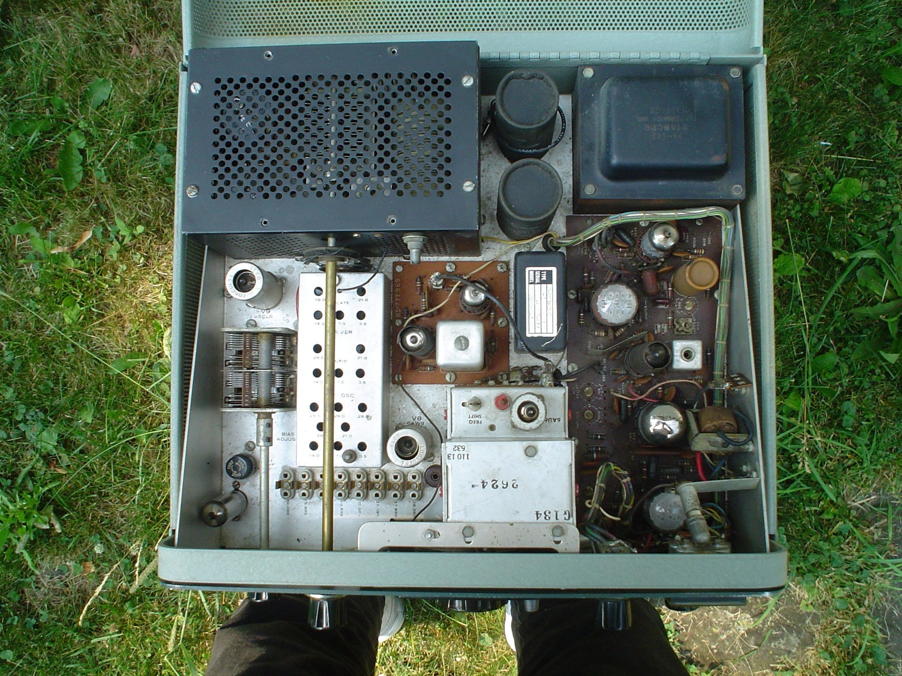
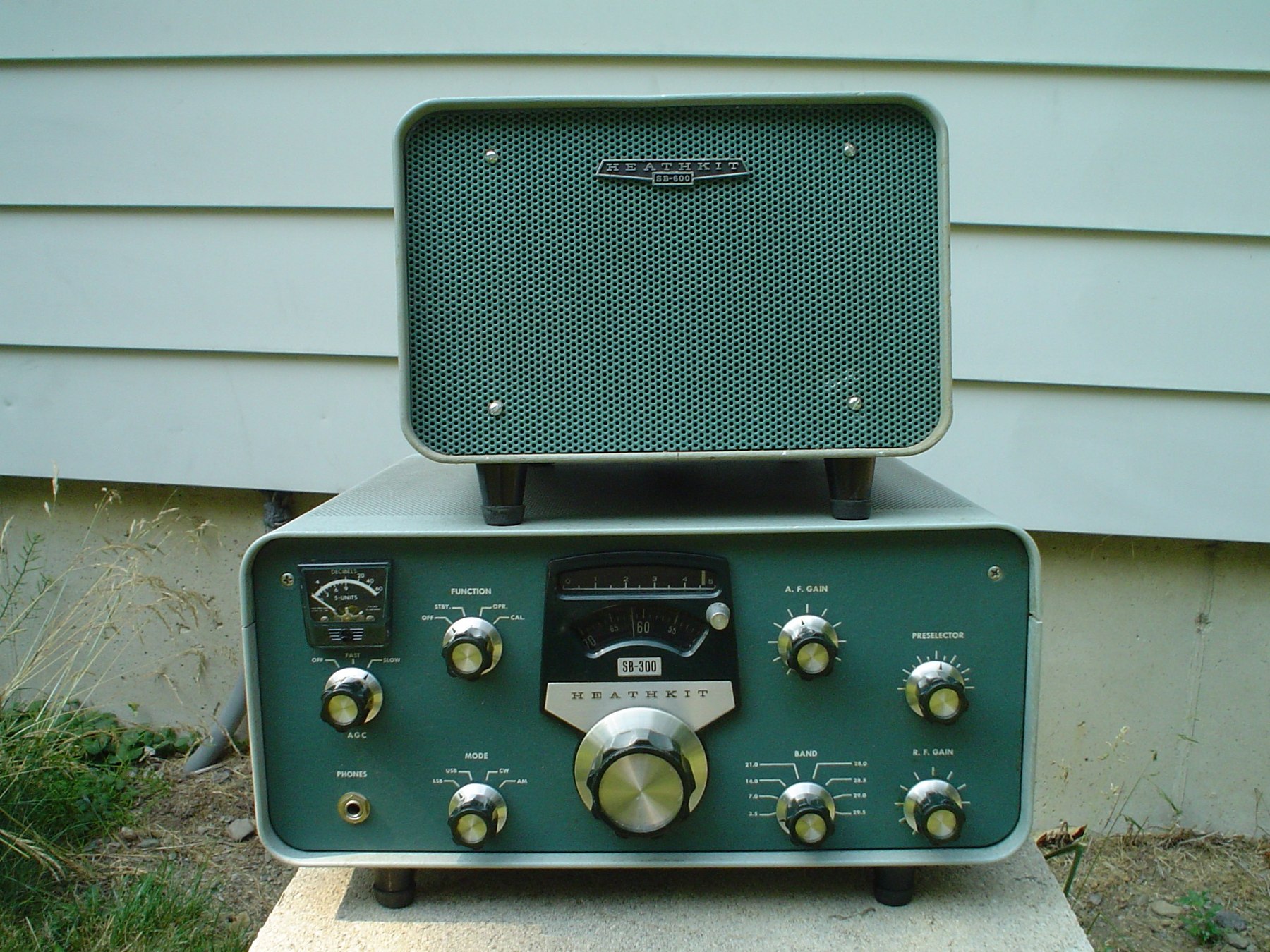
6.3 Bringing one up
The standard approach for a set that has been idle for decades applies to both units.
- Inspect for burned resistors, bulging or leaking electrolytics, and signs of earlier repairs. Check that no one has “improved” the set with parts wired against the schematic.
- Replace the electrolytics rather than trying to re-form them in a set that will be trusted with 720 V. Hayseed Hamfest’s kit for the SB-400/SB-401 shows the full list: the 100/40 µF 350 V can, the two 125 µF 450 V doubler capacitors, two 20 µF 350 V capacitors and a radial 20 µF, a 100 µF 200 V capacitor, and four 10 µF 15 V capacitors, replaced with twist-lock and 105 °C parts at the same or higher ratings (Hayseed Hamfest). In the SB-301 the main item is the four-section can, C233, which Eckweiler describes as “hard to replace” (HOTM #36). Replacement cans or discrete capacitors mounted underneath are both common solutions.
- Test the tubes, or substitute known-good ones. The SB-301 manual adds one specific warning: “The LMO was aligned using the tube supplied, Changing this tube may cause some slight difference in calibration, Replace the tube with one of the same brand if replacement is necessary” (SB-301 manual, p. 77).
- Bring the voltage up slowly on a variac or through a series lamp. For the transmitter, start with the driver tube out, a dummy load on the antenna jack, and the FUNCTION switch at STBY.
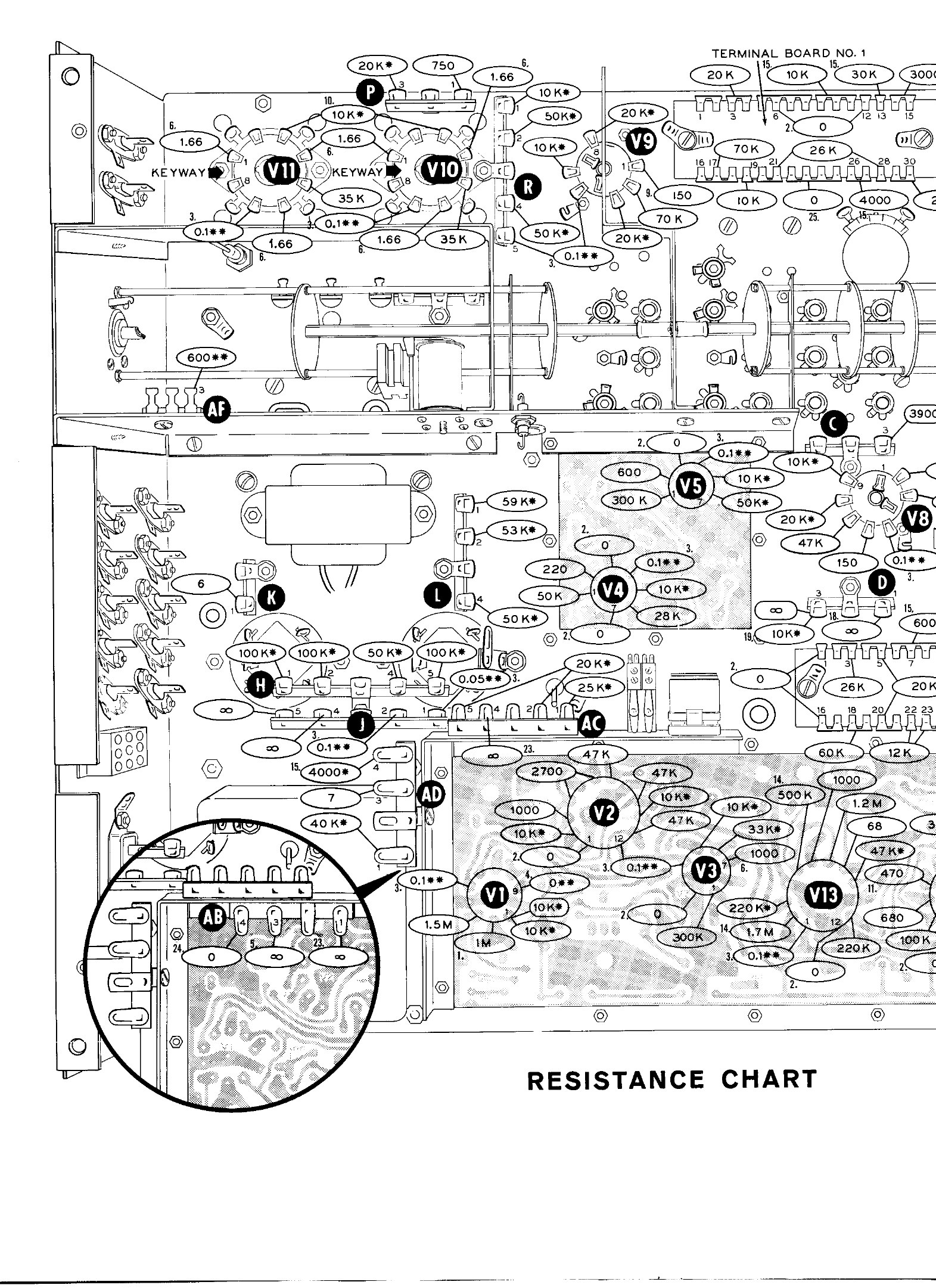
- Check the resistance and voltage charts in the manuals before aligning. Every stage has published values, taken with an 11 MΩ VTVM and allowed to vary by 10 per cent.
- Align, following the order in the Alignment volume. For the transmitter, set the final bias to 50 mA resting before any extended transmitting.
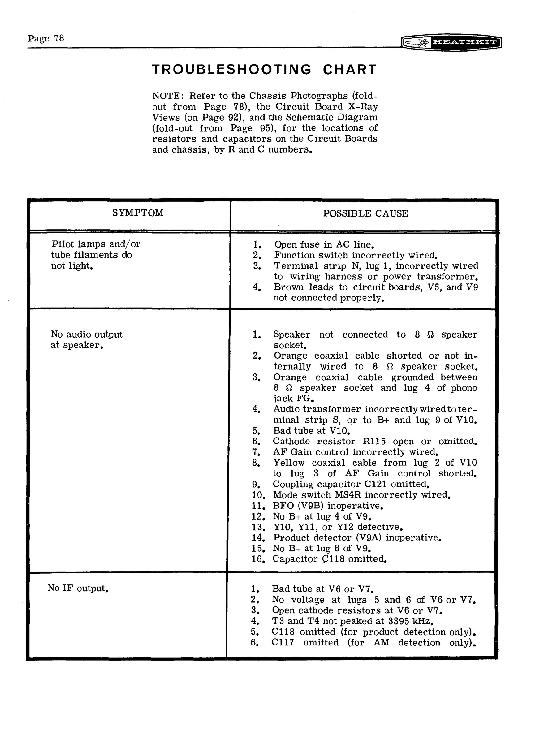
6.4 What actually goes wrong
6.4.1 The LMO
The LMO is the heart of both sets, and it is the one part the manuals say never to open. Its problems are mostly mechanical or at its connections.
- Drift or sudden frequency jumps: the phono connector. Heath issued the same bulletin for three models in July 1978: SB-300-2, SB-301-1 and SB-401-13, “LMO Drift; Intermittent Frequency Shift”. Each says to check for a dirty or corroded phono connector on the rear of the LMO and clean it (Lutz, SB-3XX bulletin index; SB-401 index). This is the first thing to try.
- Erratic tuning: the capacitor’s wiping contact. After twenty years of use, Eckweiler’s SB-301 needed its LMO capacitor bearings cleaned and relubricated, because “an intermittent sliding ground contact … caused erratic tuning” (HOTM #36). AB2RA reports the same symptom on the SB-300/SB-400 as a “jump or warble” while tuning (Heathkit Twins).
- Physical damage. One restorer found a cracked ceramic insulator inside an SB-301’s LMO, and two sets of setscrew marks on the shaft that showed earlier service (Heathkit Interests blog).
- Part numbers. Service bulletin SB-301-1D of 1 November 1967 records the change in the receiver from LMO 110-32 to 110-40. For the transmitter, SB-401-1D notes that 110-32 was no longer available and that fitting a 110-40 requires added decoupling capacitors. The same blog calls 110-40 the preferred unit and 110-32 “reportedly inferior”, but that is an owner’s view, not Heath’s. A replacement LMO is therefore not just a matter of matching the connector.
6.4.2 Relays
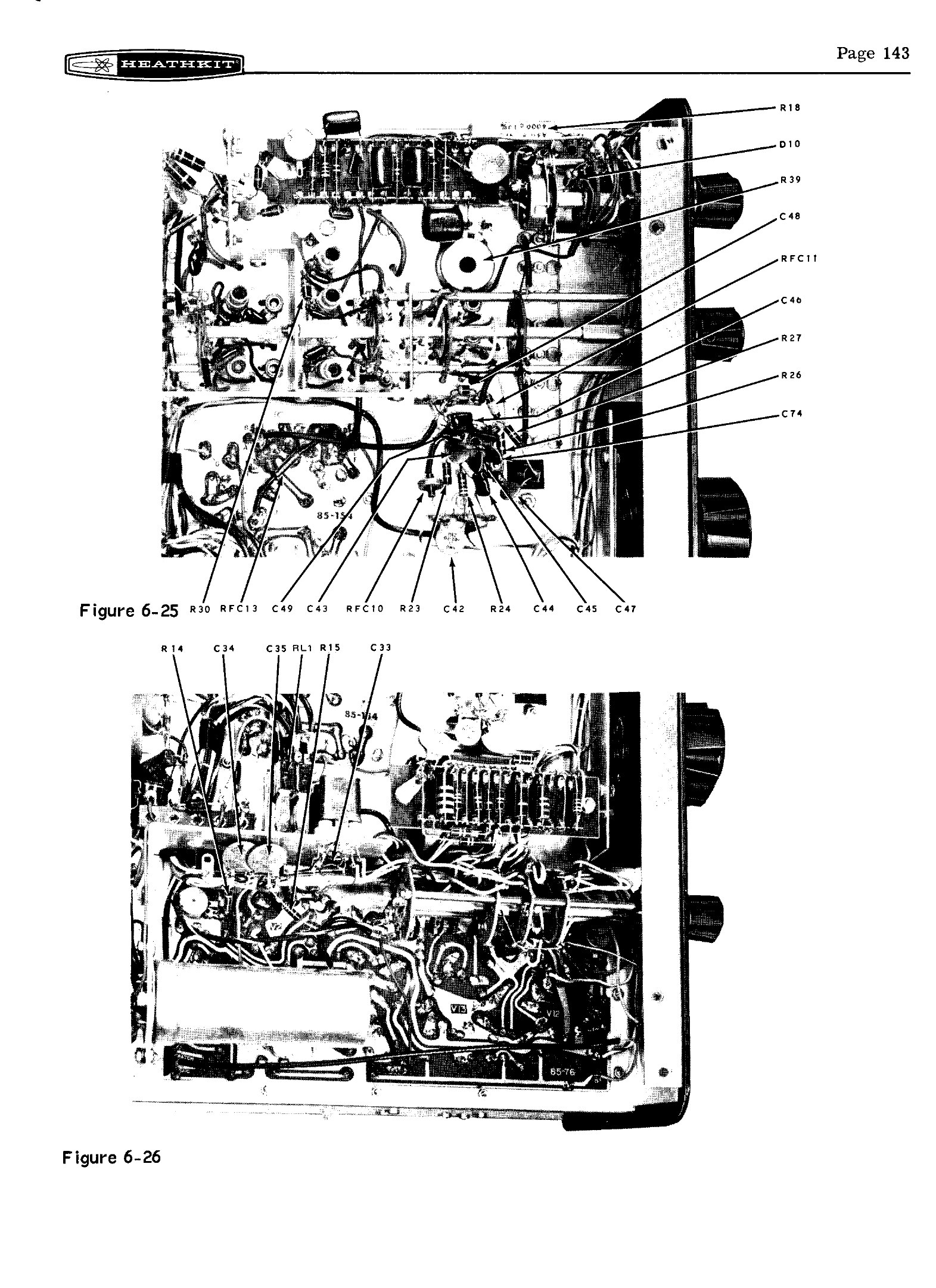
- The antenna relay hangs in transmit. This is the best-known SB-401 fault. Heath’s bulletin SB-401-2 (29 January 1974) traced it to gassy 6146s. With their screen grids left floating in receive, secondary emission from the screens could hold in the antenna relay, which is powered from the screen supply. The fix is a jumper from the unused contact, lug 7, of that section of RL1 to ground, so the screens are grounded in receive. Eckweiler made the change and it cured years of missed first syllables after a transmission (HOTM #43). Bulletin SB-401-12 then warns that resistance readings at two lugs of terminal strip AC will read zero after the modification.
- Magnetised relay. AB2RA reports that the SB-400’s antenna relay can take on a permanent magnetism that holds it in transmit, and recommends demagnetising it.
6.4.3 Components and circuits in the transmitter
The factory bulletins are the most reliable guide, and most of them apply to any SB-401 still in original condition (Lutz, SB-401 bulletin index):
Table 1 — The factory bulletins are the most reliable guide, and most of them apply to any SB-401 still in original condition ([Lutz, SB-401 bulletin index](https://puck.nether.net/pipermail/heath/1998-June/029701.html))
| Bulletin | Date | Problem | Remedy |
|---|---|---|---|
| SB-401-3D | 10 April 1967 | Weak grid drive on 20 metres | Add a 100 Ω ½ W resistor between the two 10-metre coils on the driver grid side |
| SB-401-2D | 15 May 1968 | Filter choke 46-36 (4.5 H at 120 mA) | Replace with 46-32 (4.5 H at 150 mA), only when the original fails |
| SB-401-1 | 16 February 1973 | CARRIER NULL control failing (SB-102, SB-401, HW-101) | Remount with a fibre washer and a separate ground wire |
| SB-401-2 | 29 January 1974 | Antenna relay stays in transmit | Ground lug 7 of RL1 (above) |
| SB-401-9 to -11 | 23 May 1974 | Instability, hum, driver faults | Twenty-point instability checklist; filter choke should read 120–140 Ω; driver cathode resistor 150 Ω |
| SB-401-14 | 7 August 1978 | Loading capacitor turns with the plate capacitor | Rubber grommet (73-3) on the loading shaft between the pulley and RF cage |
| SB-401-15 | 21 January 1980 | Driver plate resistor overheats | Remedy not recorded in the surviving index |
Two more come from owners. Eckweiler notes that a resistor designated R71 in the SB-400 and R402 in the SB-401 was increased from ½ W to 1 W, and that a Heath bulletin recommends the same change on the earlier model. AB2RA found that an 82 kΩ resistor on the SB-400’s terminal board can drift in value and take the balanced-modulator diodes with it, and replaced it with a 2 W part.
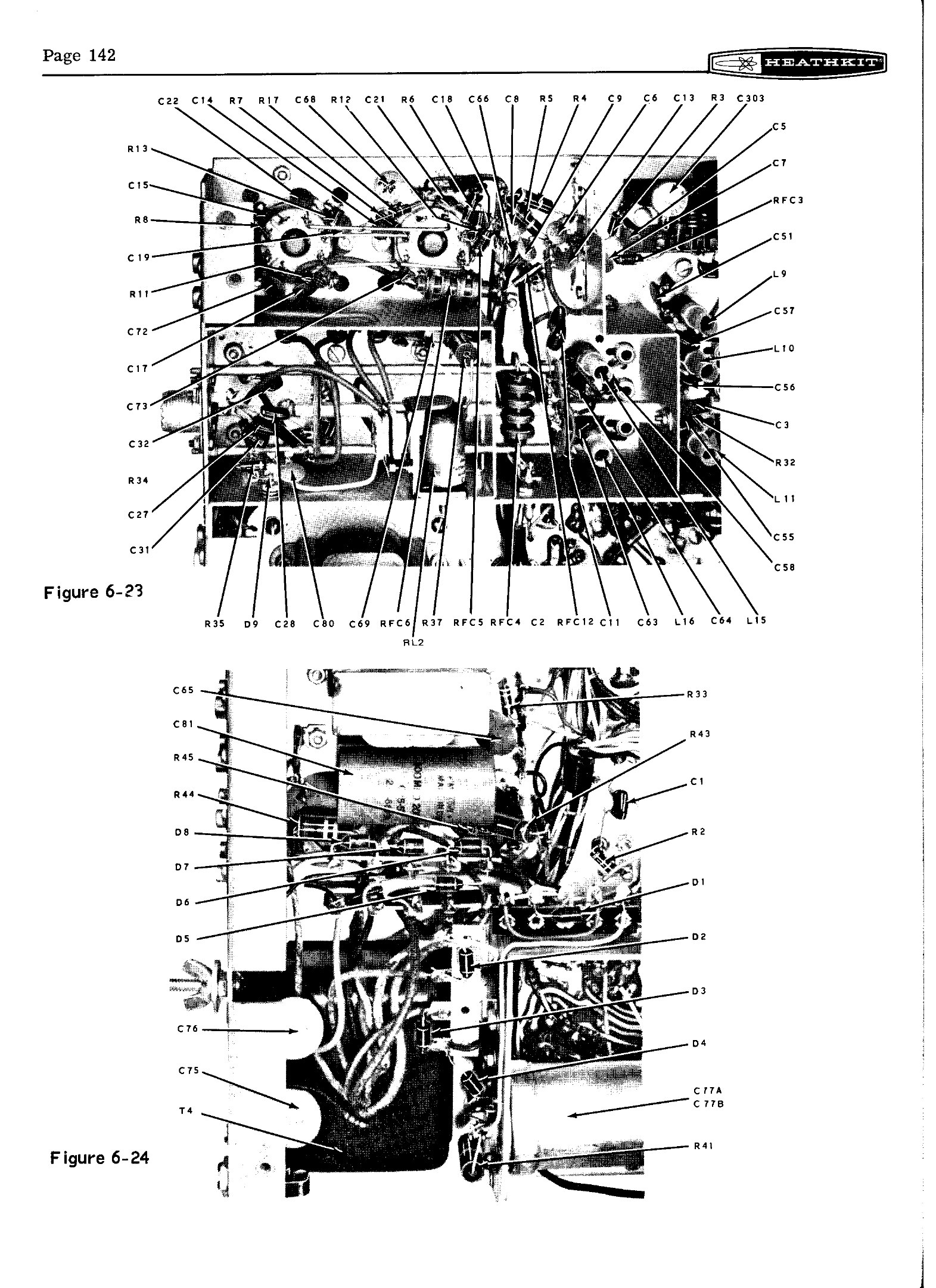
6.4.4 Components and circuits in the receiver
- Hum. Before replacing the filter can, check the ground between the RF board and the chassis. Eckweiler’s sudden hum turned out to be a loose board mounting. He cleaned the contact area and soldered the board to the chassis.
- Intermittent IF oscillation (SB-300). Bulletin SB-300-1 (1978): loose setscrews on the mode switch’s shaft coupler can let the switch sections couple capacitively. Tighten them.
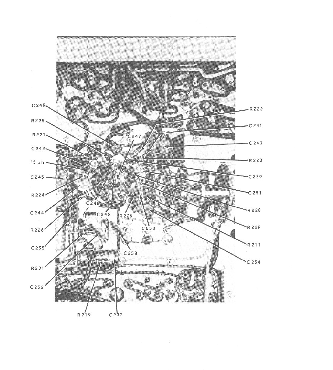
- Aged passive components. A 2019 restoration measured the ceramic disc capacitors “far below spec”, carbon-composition resistors well drifted, mica capacitors mostly within tolerance, and two tubes failing (Heathkit Interests). Resistor drift in these sets is the usual cause of wrong voltages at the audio and AGC stages.
- The noise limiter’s diodes, the AGC diodes and the germanium AM detector are easily tested out of circuit and easily replaced.
6.4.5 Tubes
Most of the types are common: 6BA6, 6AU6, 6BZ6, 6CL6, 6EW6, 6146, OA2. The Compactrons are the ones to stock: 6AS11 in the receiver and 6AV11, 6D10 and 6J11 in the transmitter. AB2RA notes they are “getting scarce”. Eckweiler’s only tube replacement in the SB-301 in over forty years was a partly failed 6AS11. The 6146 finals are still available, and their condition matters beyond output power. Gassy 6146s cause the relay-hanging fault even when they still deliver full output, which is why Heath fixed the circuit and did not tell owners to change tubes. The same restorer as above found a 6CB6A fitted where a 6BZ6 belonged, a reminder to check each tube against the schematic.
6.4.6 The SB-303
The solid-state receiver has its own bulletins. The most useful are:
- SB-303-3 (December 1970): change the 40673 MOSFETs to the RCA-branded part for consistent performance.
- SB-303-4 and SB-303-5 (1973–74): spacers under the connector plates, and tinning the board edges, to cure intermittent connections and audio instability on the plug-in boards.
- SB-303-9 (March 1976): crystal oscillator Q102 fails to start. Change it to a different transistor.
(Lutz, SB-3XX bulletin index). Plug-in board contacts are the SB-303’s version of the tube sets’ dirty switch wafers. Clean them and reseat the boards before looking further.
6.5 Modifications
Period and later modifications worth knowing about:
- Ground the finals’ screens in receive (SB-401-2). Worth doing on any SB-401.
- Better AM audio. A 470 kΩ ½ W resistor across the AM detector diode, from Heath’s News and Views, reported by Eckweiler. It only matters if the AM filter is fitted.
- SB-303 compatibility. The transmitter modification described in Transceive: two 68 Ω resistors on the FREQ CONTROL switch, and the 21 MHz trap and a capacitor removed from the mixer-bandpass board. An SB-401 modified this way needs the change reversed, or a check against the SB-303 manual, before it is used with an SB-301 again.
- A noise blanker. The SB-301 has only its limiter. Eckweiler notes that noise-blanker circuits are available, and the later SBA-104-1 blanker was bought by owners of other receivers for the same purpose (HOTM #30).
- A full rebuild. G3OOU’s rebuilt SB-301/SB-310 is the most thorough example found. It has beam-deflection mixers, an extra AGC-controlled IF stage, an RF attenuator, solid-state detectors and audio, an FM detector, and AGC-based muting for full break-in CW (G3OOU). It is a different radio afterwards, and it is noted here for completeness, not as a recommendation.
6.6 Parts today
- Capacitors. Recapping kits for the SB-400/SB-401 are sold by Hayseed Hamfest, and ordinary 105 °C electrolytics suit everything else.
- Crystal filters. The SB-301’s filters are the same family used in the SB-101, SB-102, SB-303 and HW-101 (the SSB 404-283, the SBA-301-1 AM filter and the SBA-301-2 CW filter), so they turn up on the used market. The SB-300’s larger filters are rarer and need a different mounting (Eckweiler, HOTM #36).
- Crystals. The heterodyne and carrier frequencies are all published in the manuals and in the tables in Transceive. Custom crystals can still be ordered, although a complete SBA-401-1 set costs far more than its $29.95 in 1967.
- Manuals and bulletins. Free scans of the manuals are listed in the Reference volume. The service bulletin summaries in the heath mailing-list archive are the fastest way to check whether a fault is already known.
Sources
- Heath Company. Assembly Manual, SSB Receiver Model SB-301, 595-946-01. W5RKL scan
- Heath Company. Assembly and Operation of the SSB Transmitter Model SB-401. Internet Archive
- Lutz, Joseph W. “Heathkit Service Bulletins – SB-3XX (Complete)”, 19 January 1998. Archive; “Heathkit Service Bulletins: SB-401 (Complete 1966-89)”, 13 June 1998. Archive
- Eckweiler, Bob, AF6C. “Heathkit of the Month” #30. PDF; #36, rev. A. PDF; #43. PDF
- Janis, AB2RA. “SB400 & SB300 Heathkit Twins.” Link
- Heathkit Interests blog. “SB-301 Amateur Receiver” (restoration, May–August 2019). Link
- Hayseed Hamfest. “Heathkit SB-400 / SB-401 Re-Cap Kit.” Link
- G3OOU. “Rebuilt SB-301 Receiver.” Link
Comments (0)