Heathkit · Volume 8
How a Heathkit Manual Works
A Heathkit arrived as a carton of parts and one book. The parts could be bought anywhere; what made the carton a Heathkit was the book. Heath’s engineers understood this. Chas Gilmore, who joined Heath as an engineer in 1966 and returned as vice-president of engineering and marketing in 1984, put the proportion plainly: “a typical kit design took approximately an equal number of Design Engineering and Manual Department hours—no wonder those manuals were so good” (Electronic Design, 30 November 2020). Heath spent as much on telling the builder what to do as on deciding what should be built.
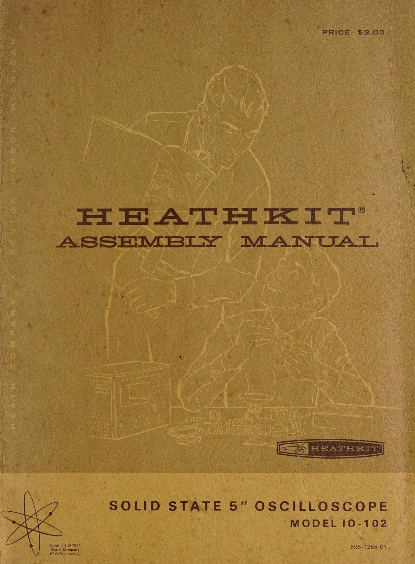
This volume treats the manual as a subject in its own right: how Heath produced one, what is on its pages and why, how the format changed from 1947 to 1990, and the tools and habits it taught. Most of the illustrations come from one book, the 1971 assembly manual for the IO-102 solid-state 5-inch oscilloscope, because it is complete, well scanned, and typical of the manual at its most developed. Earlier and later manuals are brought in to show what changed.
8.1 From instruction sheet to book
The first Heathkit, the O-1 oscilloscope of 1947, came with a single sheet of instructions. Erich Brueschke and Michael Mack, in the fullest history of the company, describe how the manual grew from there by iteration. At first “manuals were written by the design engineer and consisted of one or more mimeographed pages of text without step-by-step instructions”, accompanied by blueprints of the schematic and a pictorial of the basic parts layout. Later came “beautiful pictorials and step-by-step instructions with check-offs for each step—and in some cases, large foldout pictorials and schematics” (Brueschke and Mack, AWA Review 32, 2019, p. 146).
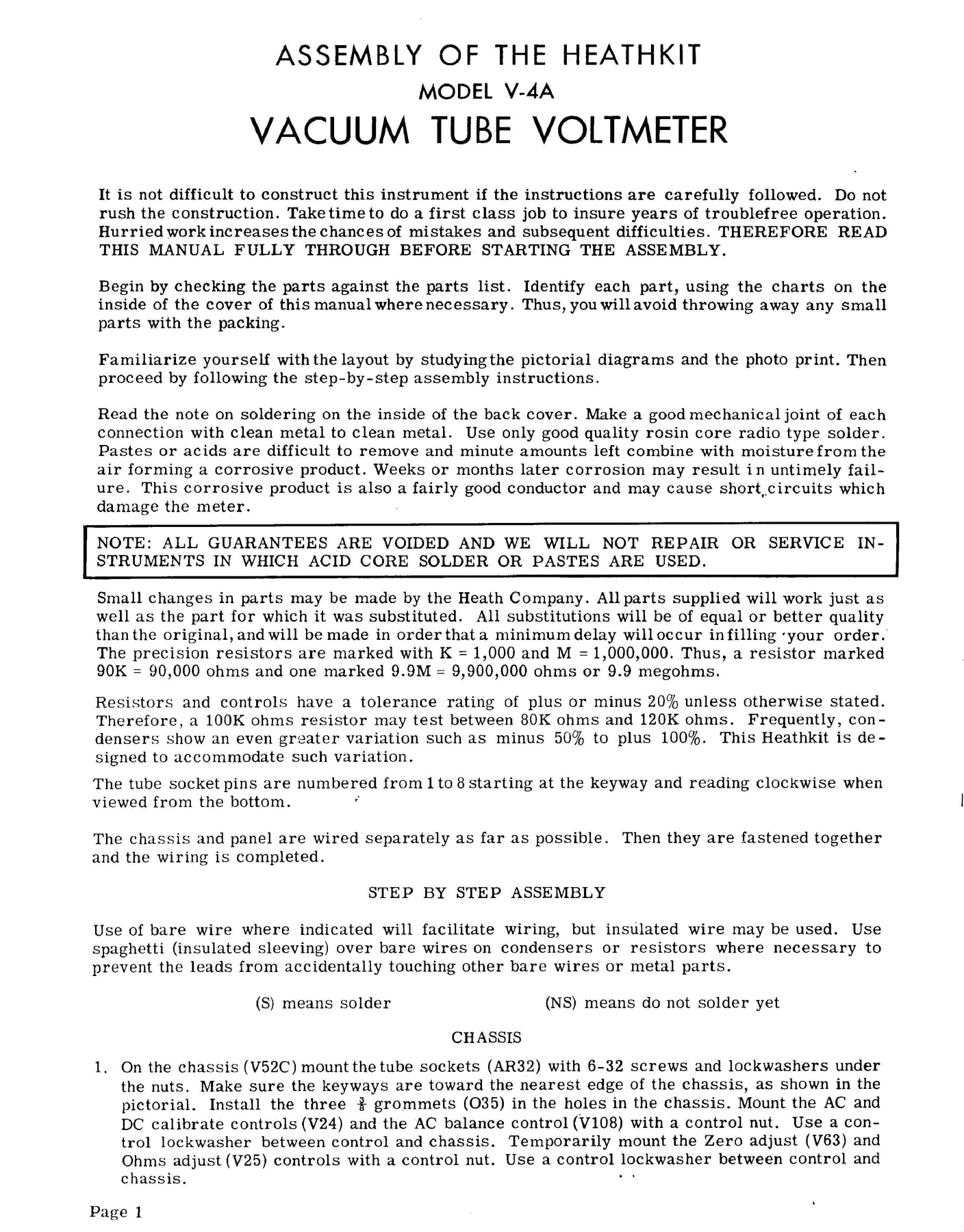
The V-4A vacuum-tube voltmeter of about 1950 shows the intermediate stage. Its first page is almost entirely prose, set in a typewriter-like face, and it opens with advice that every later manual would repeat in some form: “It is not difficult to construct this instrument if the instructions are carefully followed. Do not rush the construction.” The builder is told to check the parts against the list, to identify them with the charts inside the cover, to study “the pictorial diagrams and the photo print” before starting, and to “use only good quality rosin core radio type solder”. A boxed warning follows: “ALL GUARANTEES ARE VOIDED AND WE WILL NOT REPAIR OR SERVICE INSTRUMENTS IN WHICH ACID CORE SOLDER OR PASTES ARE USED.” Numbered steps are present, but they run on as paragraphs rather than as separate boxed lines (Internet Archive, V-4A manual).
By the mid-1950s the format had settled. Brueschke and Mack take the V-7A voltmeter (1955–1961, $24.50) as their example of a mature manual: 34 pages titled “Assembling and Using Your Heathkit Vacuum Tube Voltmeter Model V-7A”, with colour-code information, parameter values, schematics, “numerous beautiful illustrations”, and a pair of boxes at each step, one to mark whether a joint should be soldered (S) or not yet soldered (NS), the other to tick when the step was done (Brueschke and Mack, pp. 146–147). The V-7 was also Heath’s first printed-circuit kit, and Brueschke and Mack note that management had worried a printed board would take something away from the building experience. Gilmore recalled the same argument: “there were many at Heath who questioned this move, concerned a PCB would ‘ruin’ the kit building experience. Clearly this wasn’t the case” (Electronic Design).
8.2 How Heath made a manual
8.2.1 The Manual Department
By the 1960s and 1970s manual writing was a department, not a task. Gilmore described Heath engineering as “two major groups: Design Engineering and the Manual department, each about 80 people out of some 700 in total at Heath.” The Manual Department “consisted of Writers, Editors, Illustrators and a support group” (Electronic Design). In other words, more than a tenth of the whole company worked on the books.
8.2.2 The hand-off
Gilmore’s account of the process is the most detailed on record. When a design engineer had a final prototype that met its specifications, he “turned a prototype and five sets of parts along with a draft circuit description and other assembly information over to the assigned manual writer.” The writer then built the product himself, “consum[ing] one or two sets of parts building the product to write and check out the assembly process.” Illustrators meanwhile “prepared the detailed and often expanded-view drawings to accompany the assembly step-by-step instructions.” The writer also produced the circuit description and the troubleshooting guide (Electronic Design).
On the choice of drawings over photographs, Gilmore gave the reason in one sentence: “Early on, Heath discovered drawings conveyed much more information than photographs and the drawing could delete clutter that might appear in a photograph.” The early V-4A still shipped with a “photo print”. By the 1960s the photograph had been demoted to the occasional chassis view at the back of the book, and the line drawing did the work.
8.2.3 Pre-proof, proofbuild, post-proof
Two formal trials followed the draft. In the pre-proof, three sets of parts “were packed as in production”, and employees from the manual department, engineering and product management built the product from the draft manual. Engineering tested the results, the writer collected every marked-up copy, and a revised manual was produced. Then came the proofbuild: 25 sets of parts packed to the final packing instructions, built by “20+ employees … selected from a pool of interested people.” A good proofbuild sent the product to production and a catalogue date; a poor one triggered a post-proof (Electronic Design).
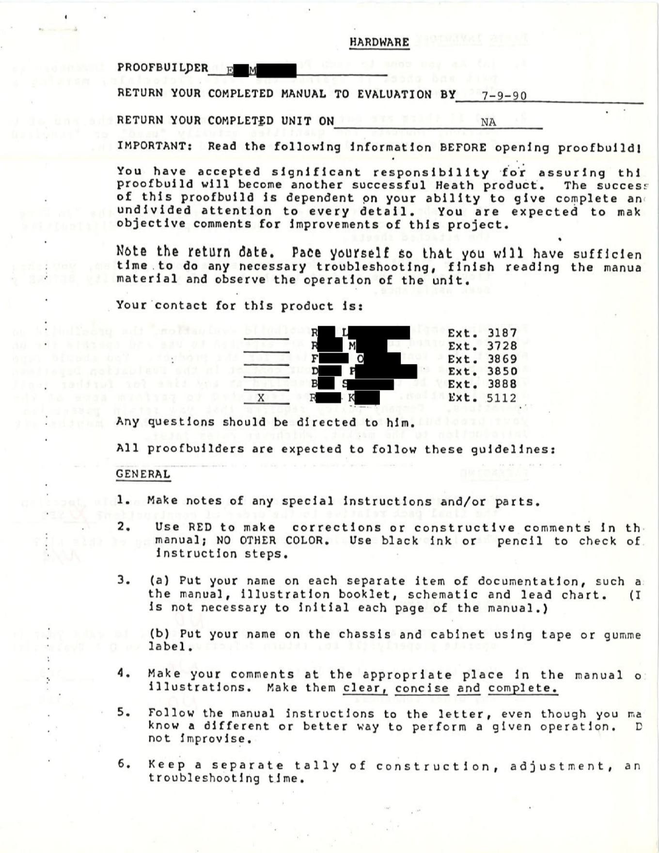
A rare internal document shows what a proofbuilder actually received. The papers for the H-5100 desktop computer of 1990, preserved with employee names redacted, include the four-page “Hardware” proofbuild form (QA form 4514-1). It told the employee: “You have accepted significant responsibility for assuring this proofbuild will become another successful Heath product.” The rules followed (Internet Archive, H-5100 assembly manual and proofbuild report):
- Use red to make corrections or comments in the manual, “NO OTHER COLOR”; use black ink or pencil to check off steps.
- Put your name on the manual, illustration booklet, schematic and lead chart, and on the chassis and cabinet.
- “Follow the manual instructions to the letter, even though you may know a different or better way to perform a given operation. Do not improvise.”
- Keep a separate tally of construction, adjustment and troubleshooting time.
- At each parts list, inventory every part against the Parts Pictorials, counting all hardware.
- If anything goes wrong, follow the “In Case of Difficulty” section first, then troubleshoot “to the best of your ability BEFORE you seek assistance.”
- Keep the proofbuild unit and use it as a continuing field test “for one year or until three months after introduction to the market, whichever comes later.”
- Check that the scales printed at the bottom of manual pages are accurate against a real ruler.
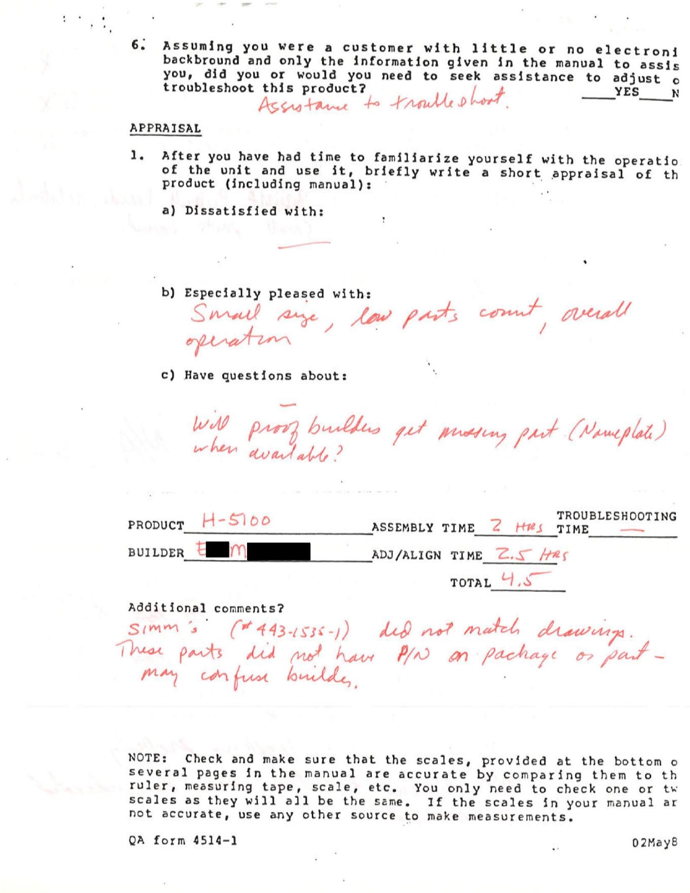
The form then asks questions that show what Heath measured. Were the parts bags in a sensible order relative to construction? Was any part of the assembly “overly difficult”? Rate your “confidence level” on a scale of 1 to 5, immediately after assembly and again after adjustment. “Assuming you were a customer with little or no electronic background and only the information given in the manual to assist you, did you or would you need to seek assistance?” This H-5100 builder recorded two hours of assembly and two and a half of adjustment and alignment. In red, the builder rated confidence high (“small parts count”) and noted that the SIMM memory modules “did not match drawings” and that some parts lacked part numbers on their packages. These are the kinds of discrepancy the proofbuild existed to catch before a customer met them.
8.2.4 Designing the kit around the manual
The manual shaped the product as well as describing it. Gilmore listed features “derived from customer experience”: Heath supplied rosin-core solder in the kit “to ensure the use of rosin core solder vs. damaging acid core solder (90% of build problems were associated with soldering)”, and added a plastic Nut Starter to most kits. Colour television kits, whose builders were unlikely to own a meter, came with a very simple VOM kit for alignment; in FM receivers, the tuning meter was switched to serve as an alignment meter. “Heathkits didn’t presume the customer would supply any critical items. If they needed it, it was in the kit” (Electronic Design).
8.3 Anatomy of an assembly manual
The IO-102 manual (1971; 595-1285-01) is a typical manual of Heath’s mature period. Its scan runs to more than 150 page images including fold-outs (Internet Archive). Its sections follow a fixed order that a builder of any other Heathkit of the period would recognise.
8.3.1 Inside the front cover: the component chart
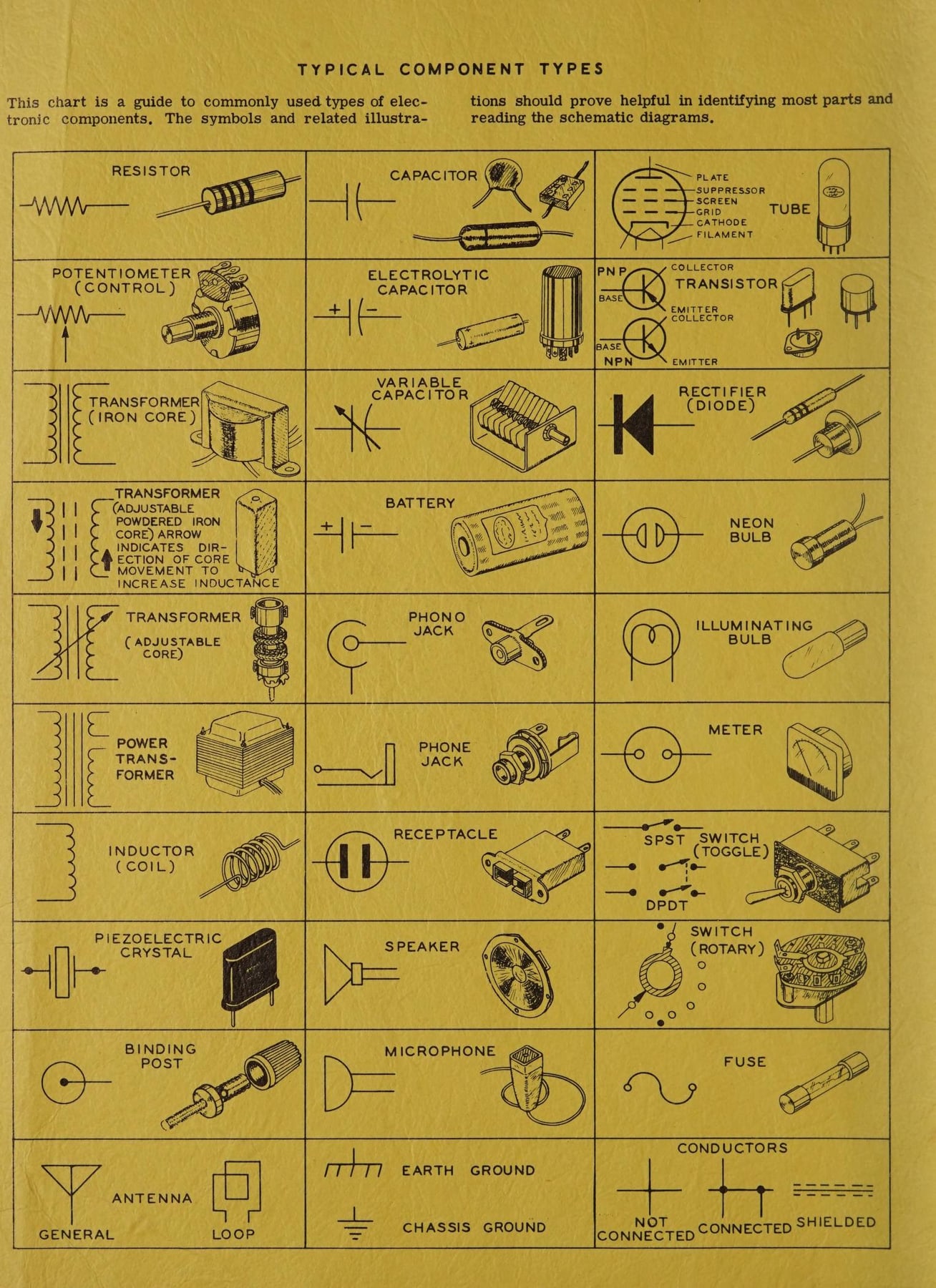
The first thing inside the cover is a full-page chart headed “Typical Component Types”: drawings of each kind of part (resistors, controls, capacitors of several constructions, diodes, transistors, transformers, switches, lamps, jacks, plugs, crystals, meters, the CRT) beside the corresponding schematic symbol. The chart teaches two languages at once, what a part looks like on the bench and how it is drawn on the schematic, so that the builder can move between the pictorial and the circuit diagram later in the book.
8.3.2 Table of contents and the modular structure
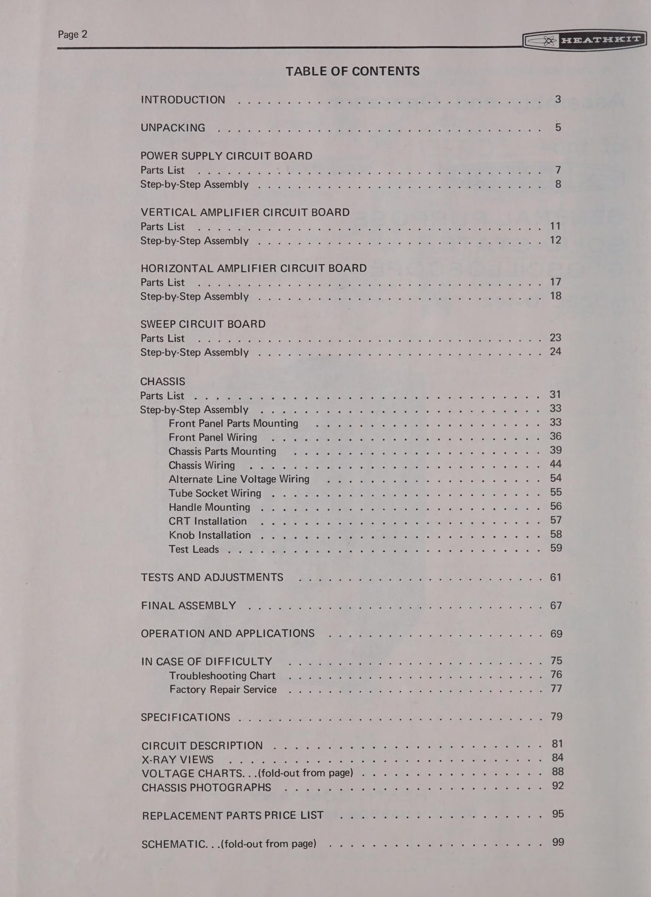
The contents page shows the most important structural decision in a large Heath manual: the kit is split into modules, each with its own parts list and its own step-by-step section. The IO-102 builds its power-supply board, vertical-amplifier board, horizontal-amplifier board and sweep board in turn, then the chassis (front panel parts, front panel wiring, chassis parts mounting, chassis wiring, alternate line-voltage wiring, tube socket, handle, CRT, knobs, test leads), then tests and adjustments, final assembly, operation, “In Case of Difficulty”, specifications, circuit description, voltage charts, a replacement parts price list and the fold-out schematic.
8.3.3 Unpacking
Unpacking was a procedure. The IO-102 carton held packages stamped 1 to 4 and a loose remainder that became “package #5”. “You will be directed to open each package as it is needed,” the manual says, and “to avoid intermixing parts, do not open any of the parts packages, until directed to do so.” Any part in its own numbered envelope “should be placed back in its envelope after it is identified, until that part is called for in a step.” The same page sends the builder to the separate Kit Builders Guide for general instruction on parts identification, tools, wiring and soldering (IO-102 manual). Packing the kit in construction order kept a 400-part instrument manageable on a kitchen table, and it is why the proofbuild form asked whether the bags were “in a reasonable location in the final pack relative to the order of construction.”
8.3.4 The parts list
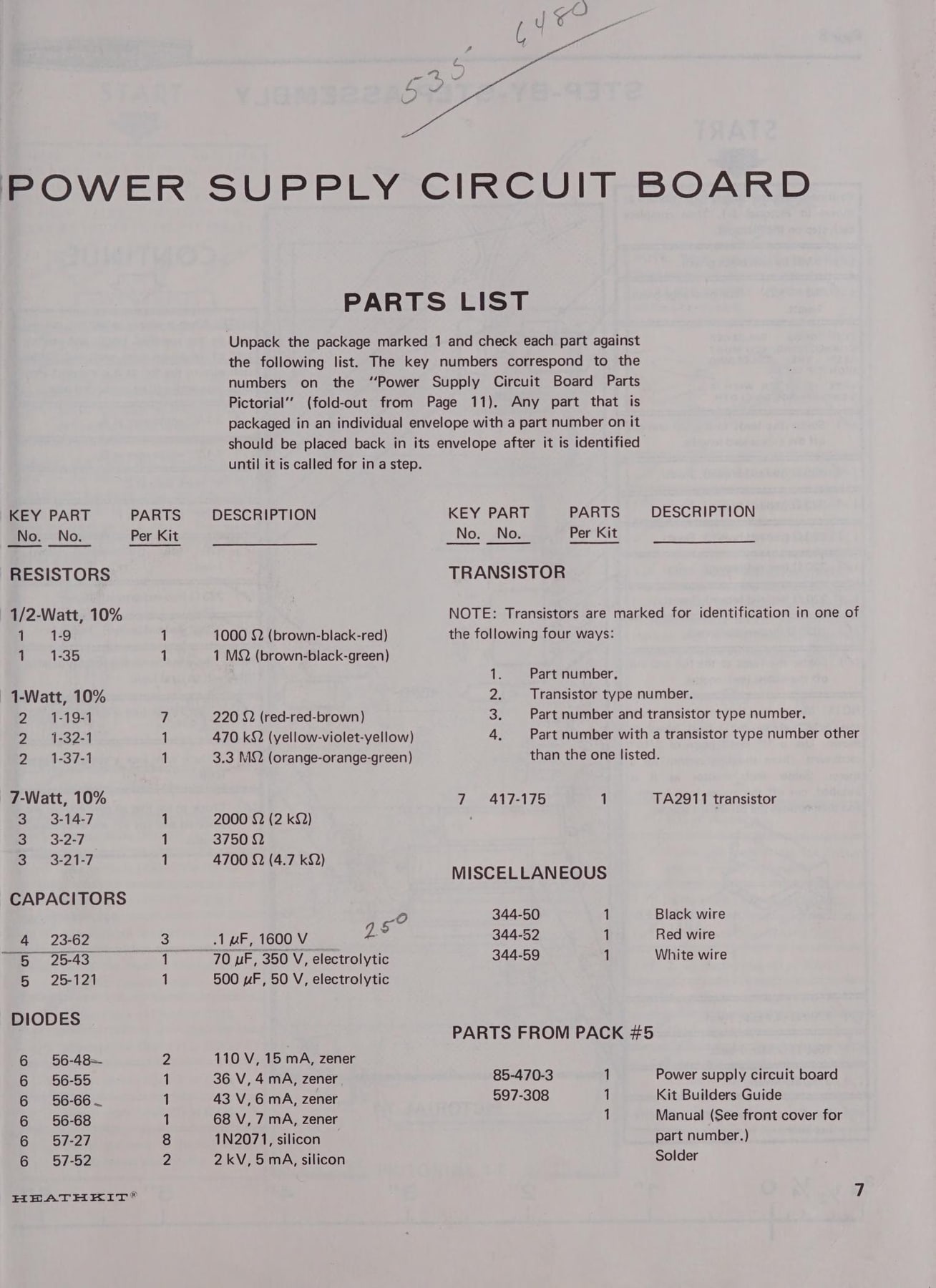
Each module opens with a parts list in four columns: key number (matching a numbered drawing on the fold-out “Parts Pictorial”), Heath part number, quantity per kit, and description. Resistors are described by value and by colour bands spelled out in words: “1 MΩ (brown-black-green)”, “220 Ω (red-red-brown)”. Transistors come with a note on the four ways they might be marked. The last lines list the parts to take from pack #5, including a copy of the Kit Builders Guide (597-308), the manual itself (“See front cover for part number”) and the solder (IO-102 manual).
8.3.5 The step-by-step page
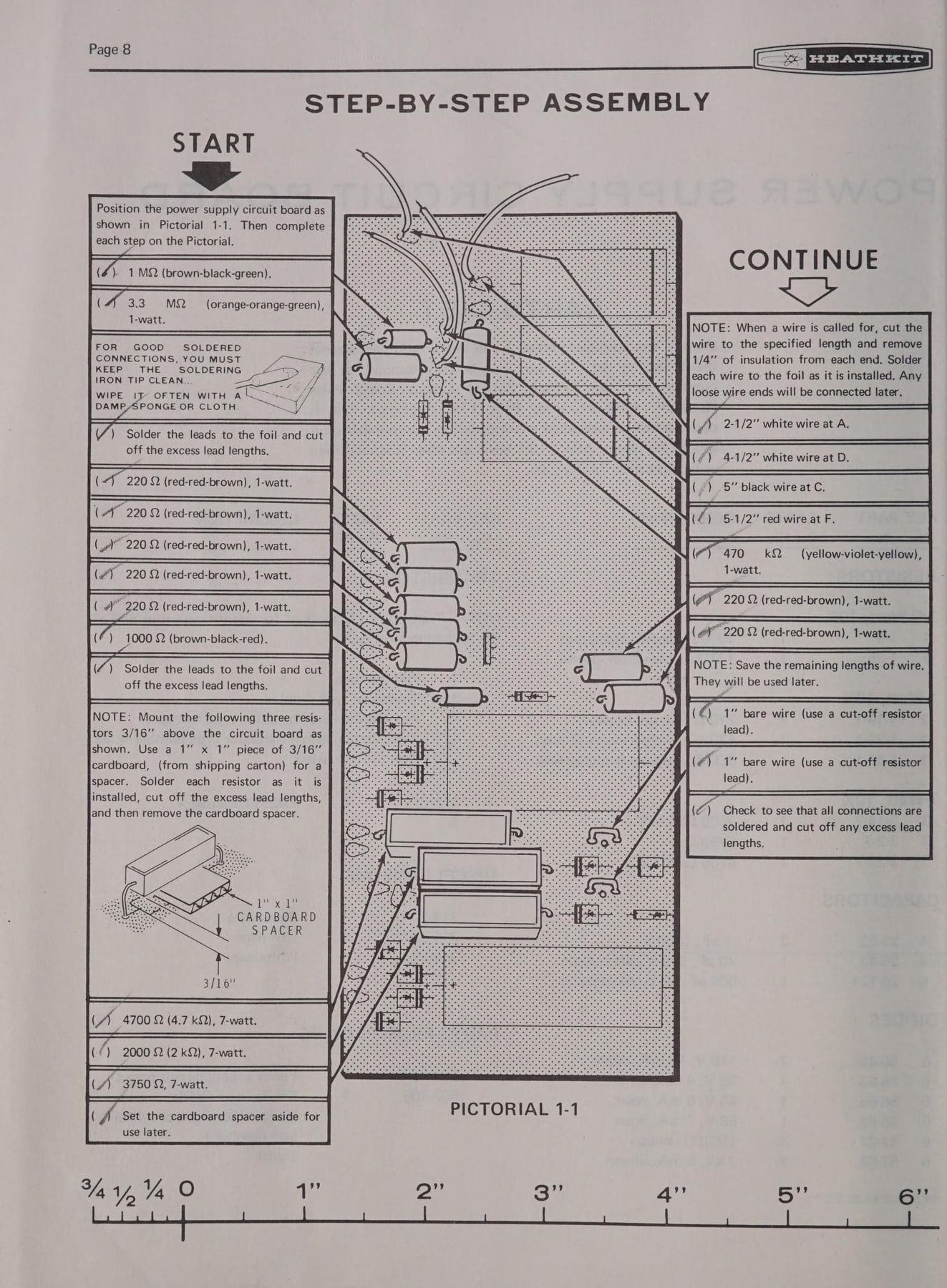
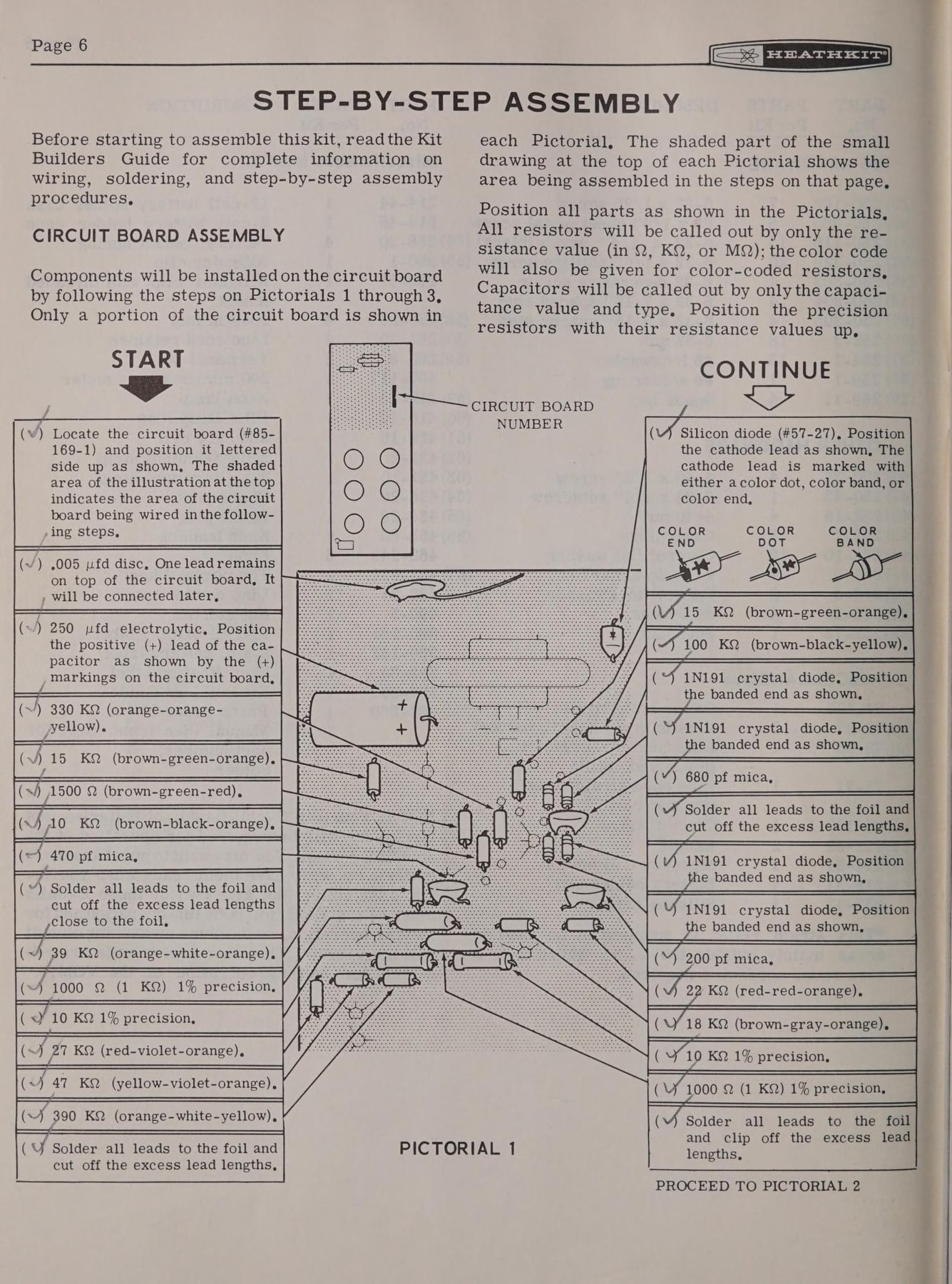
The step-by-step page is the part of the Heath method people remember best. On the IO-102’s page 8, a heavy START arrow at the top left points into a column of ruled boxes, each holding one action and a pair of parentheses to tick: ”( ) 1 MΩ (brown-black-green).” ”( ) Solder the leads to the foil and cut off the excess lead lengths.” The column runs down the left of the page and a second column, under CONTINUE, runs down the right. Between them is Pictorial 1-1, a drawing of the circuit board with a leader line from each step to the exact hole where the part goes. Notes are set as boxed paragraphs among the steps: a reminder to wipe the soldering iron tip on a damp sponge, and an instruction to mount three power resistors 3/16 inch above the board using “a 1” x 1” piece of 3/16” cardboard (from shipping carton) for a spacer”, with a drawing of the spacer in place. Along the bottom of the page is a printed ruler, 0 to 6 inches, for measuring wire lengths and lead spacing without leaving the book (IO-102 manual, p. 8).
Several conventions on this page served the builder directly:
- One action per step. Each box holds a single part or operation, so that an interrupted builder can find the exact point to resume.
- Check-off parentheses. Ticking each step turns the manual into a record of progress. This copy of the IO-102 still carries its first owner’s pencil marks.
- Soldering is an explicit step. Parts are installed in groups and then soldered in a separate step (“Solder the leads to the foil”), which reduces missed joints.
- The page is laid out to match the work. Steps sit next to the drawing they refer to, in the order the builder’s hand moves across the board.
- Scales on the page. Printed rulers let the builder measure without a separate tool. The 1990 proofbuild form still told testers to check that these scales were accurate.
The IM-25 VOM manual of 1967 shows the same layout four years earlier, with the steps wrapped around Pictorial 1, resistor colours spelled out step by step, and a closing instruction to “PROCEED TO PICTORIAL 2” (Internet Archive, IM-25 manual).
8.3.6 Pictorials and details
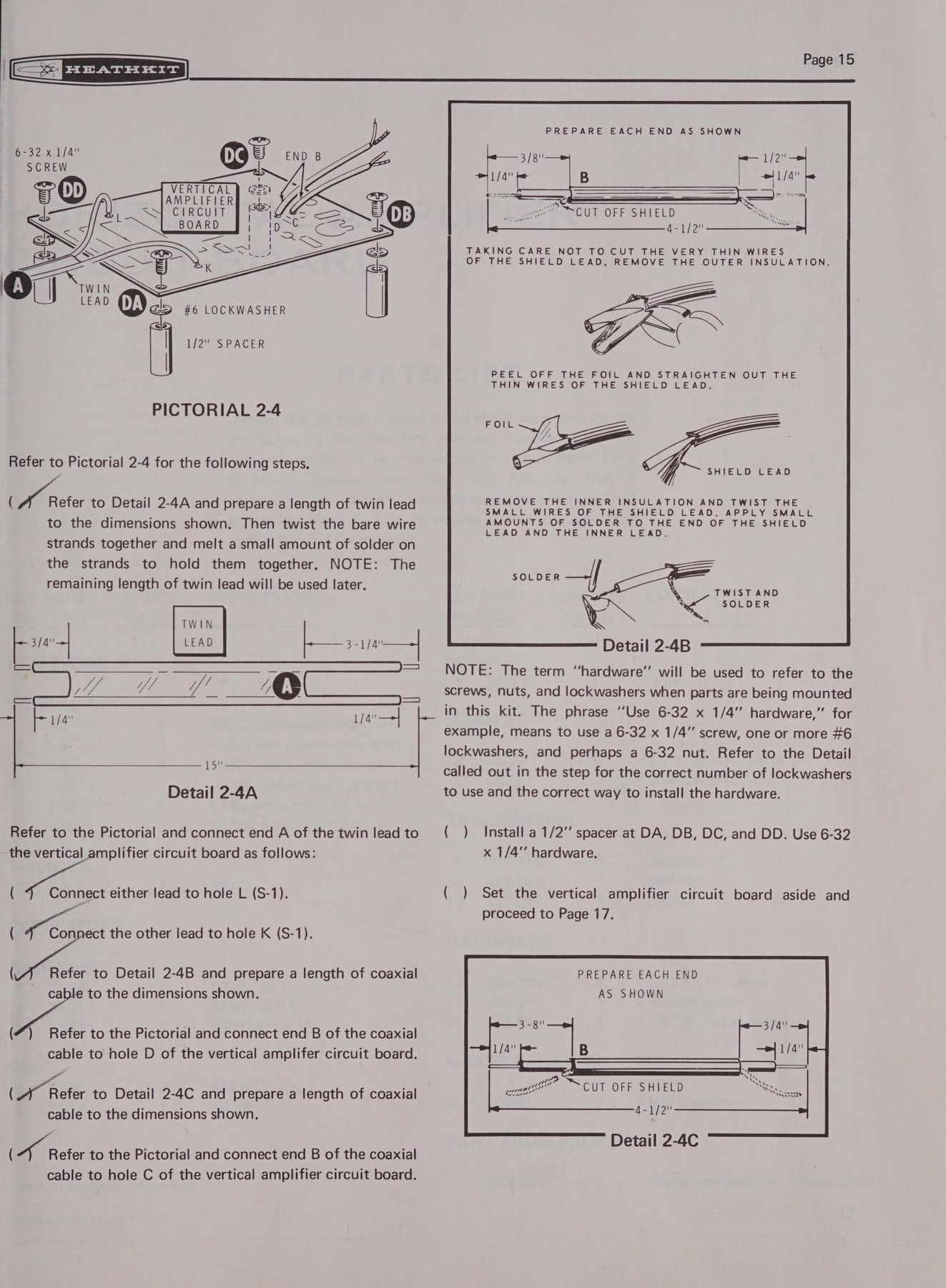
Where a single drawing could not show everything, Heath added details: small enlarged drawings, numbered to match the pictorial (Detail 2-4A, 2-4B), showing a single operation such as how a lead is bent around a lug or how hardware stacks up. One IO-102 page shows Pictorial 2-4 with Details 2-4A to 2-4C and a stack of hardware (screw, lockwasher, 1/2-inch spacer) drawn in exploded form (IO-102 manual). By 1990 the H-5100 manual stated the convention in words: “Pictorials show the overall operation for a group of steps; Details generally illustrate a single step” (H-5100 assembly manual).
Large pictorials were printed as fold-outs, bound so that they opened out beside the text they served. The parts list for the IO-102 power-supply board points to a “Power Supply Circuit Board Parts Pictorial (fold-out from Page 11)”. This let the drawing sit next to the step even when the steps ran on for several pages.
8.3.7 X-ray views
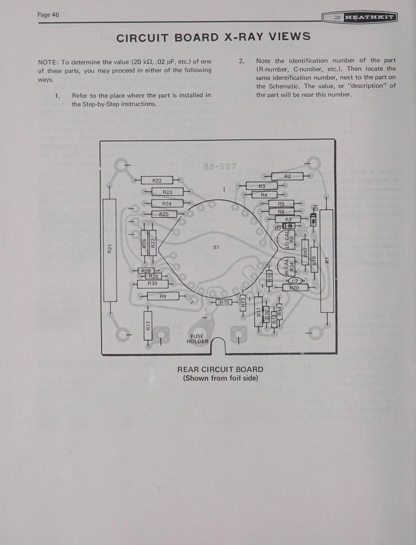
A finished circuit board hides its parts. The X-ray view, printed near the back of the manual, is a drawing of each board as though the builder could see through it, with every component outlined and labelled with its circuit designation (R12, C4, Q9). The instructions explain how to use it: to find the value of a part, either go back to the step where it was installed, or note its identification number on the X-ray view and “locate the same identification number next to the part on the Schematic” (IO-102 manual, p. 84; IM-105 manual, p. 46). The X-ray view connects three documents: the physical board, the pictorial and the schematic. It is what made a finished Heathkit serviceable by its owner years later.
8.3.8 Tests, adjustments and operation
After assembly came Tests and Adjustments, written to need as little equipment as possible. The IM-25 manual, for instance, says its calibration steps “use a minimum of equipment”. The IO-102 follows with Operation and Applications, a short course in using an oscilloscope: waveform display, audio amplifier measurements, and so on. The manual assumes the owner is learning the instrument as well as building it.
8.3.9 In Case of Difficulty
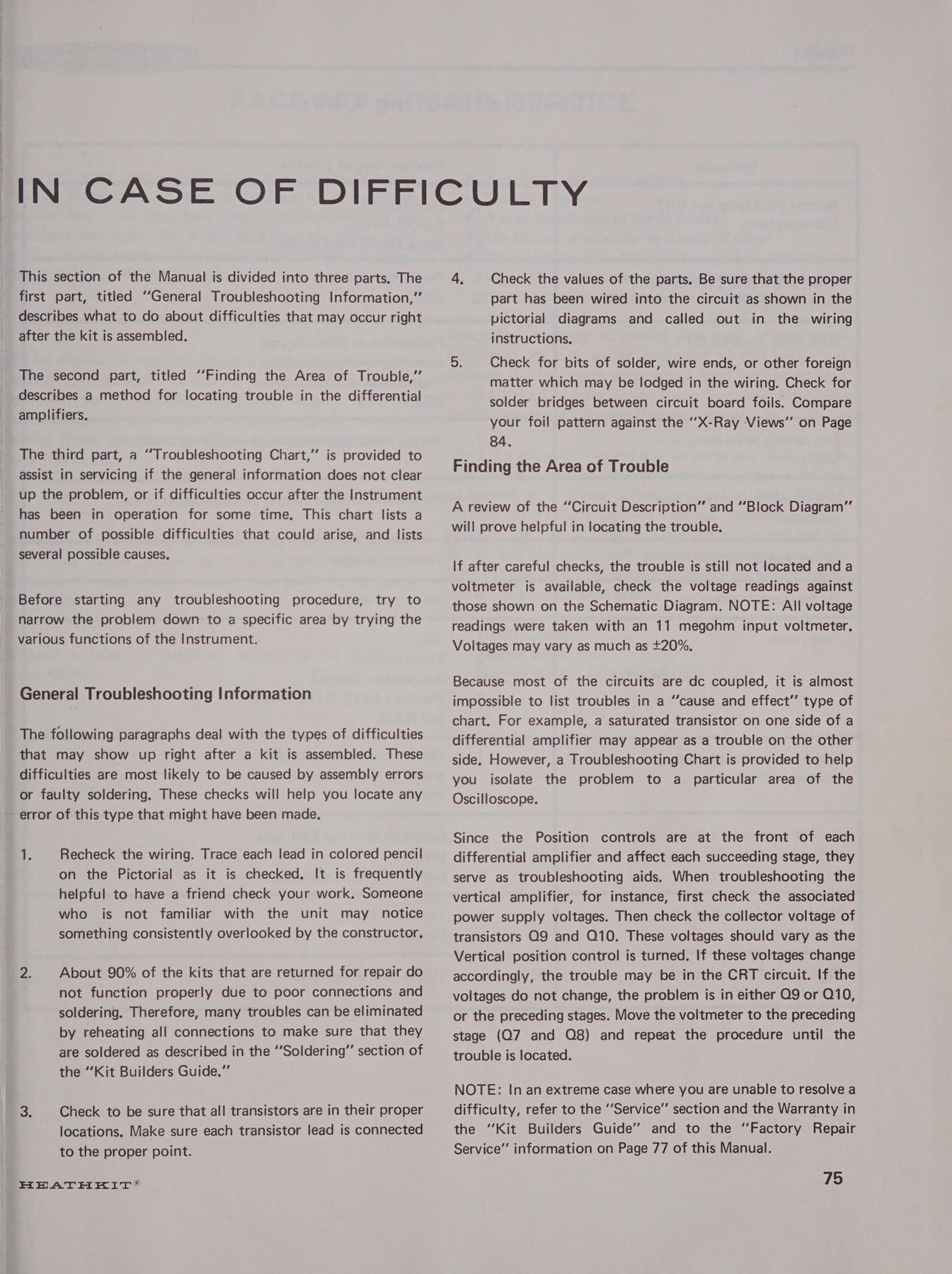
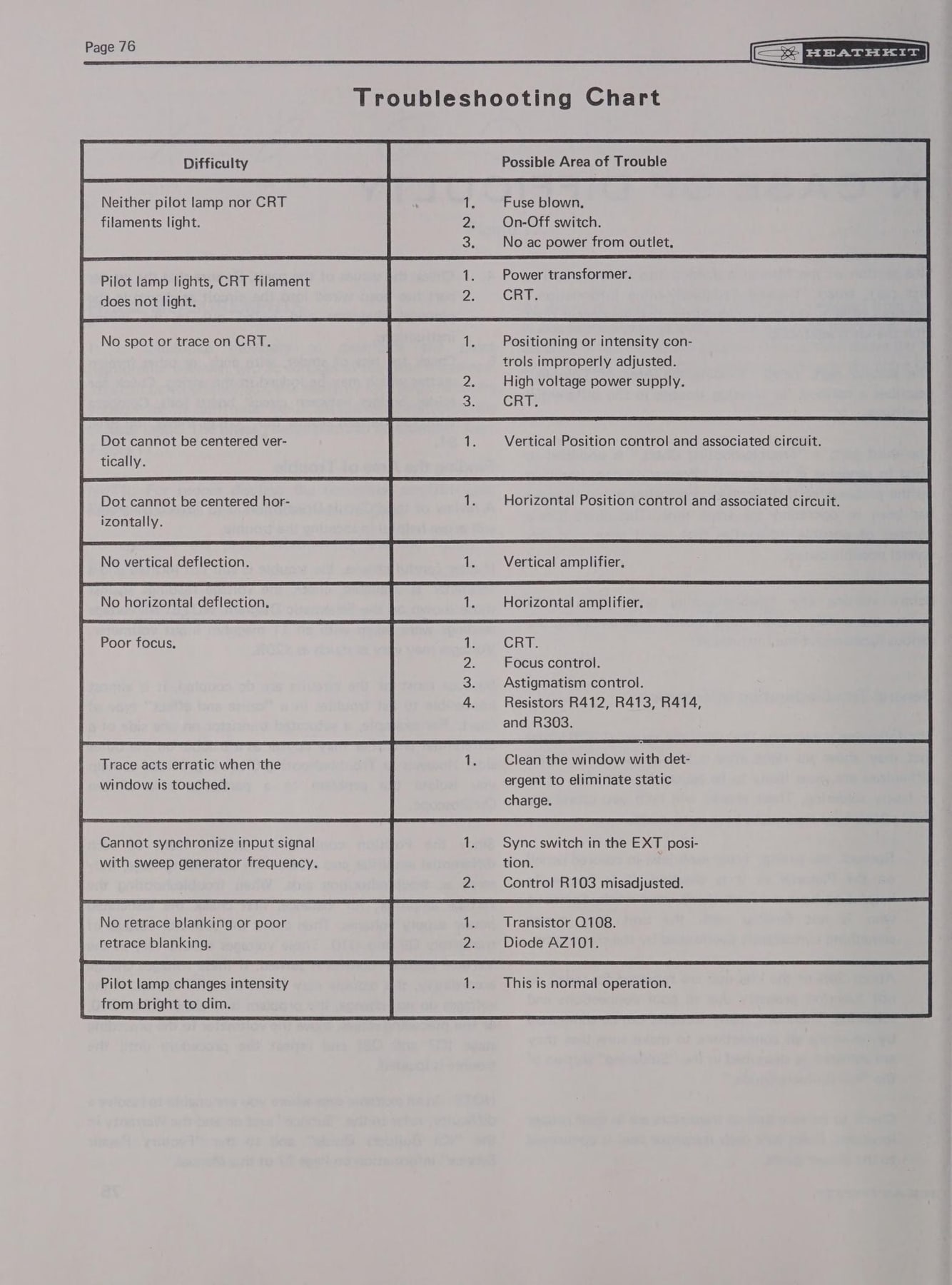
Every Heath manual included a section headed “In Case of Difficulty”, and it is where the company’s service philosophy shows most clearly. The IO-102 version is in three parts: “General Troubleshooting Information” for problems found right after assembly, “Finding the Area of Trouble” (a method for isolating faults in the differential amplifiers), and a Troubleshooting Chart. The first instruction is to “recheck the wiring”, tracing “each lead in colored pencil on the Pictorial as it is checked”, and to have a friend look too, because “someone who is not familiar with the unit may notice something consistently overlooked by the constructor.” The second gives the statistic that justified the rosin-core solder in every box: “About 90% of the kits that are returned for repair do not function properly due to poor connections and soldering” (IO-102 manual, p. 75).
The Troubleshooting Chart is a two-column table, “Difficulty” against “Possible Area of Trouble”, listing symptoms (“Neither pilot lamp nor CRT filaments light”, “No vertical deflection”) with the parts, stages and adjustments to check, often down to individual transistor numbers. The proofbuild form’s abbreviation “ICOD” shows how central the section was inside Heath: everyone knew what it meant.
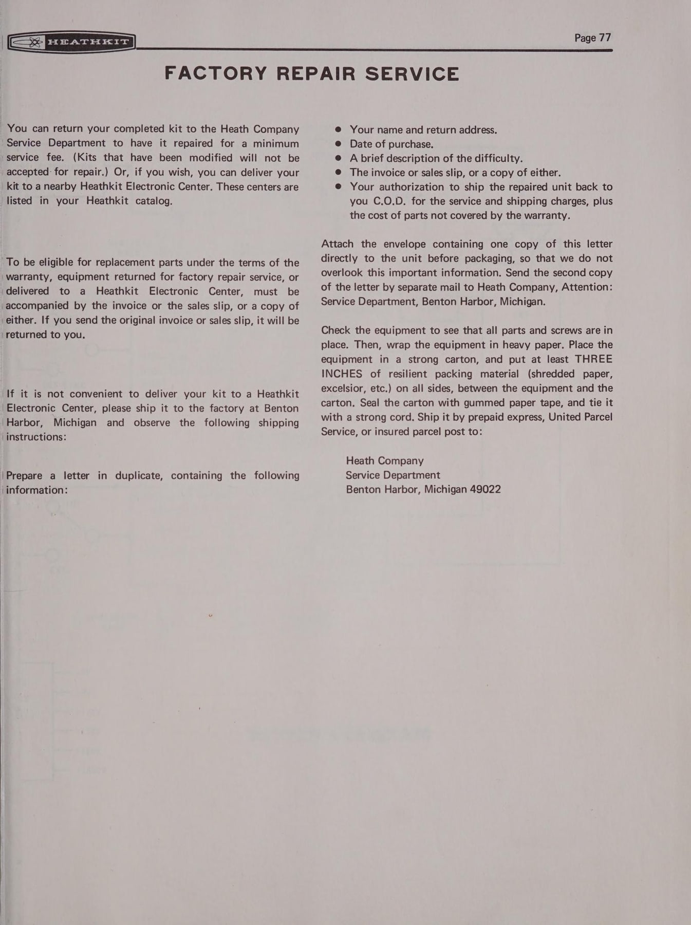
If the owner still could not fix it, the manual described Factory Repair Service: return the completed kit “for a minimum service fee” (modified kits were refused), or take it to a nearby Heathkit Electronic Center. The IO-102 page sets out the shipping procedure in detail: a letter in duplicate with name, date of purchase, description of the difficulty, the invoice, and authorisation to return the unit C.O.D.; one copy fastened to the unit and the other mailed separately; “at least THREE INCHES of resilient packing material (shredded paper, excelsior, etc.) on all sides” (IO-102 manual, p. 77). Behind this page stood the service culture that Gilmore summed up in the company’s slogan, “We will not let you fail”, backed by “a robust Customer Service department” and a staff of technical correspondents who answered builders’ letters (Electronic Design).
8.3.10 Circuit description and block diagram
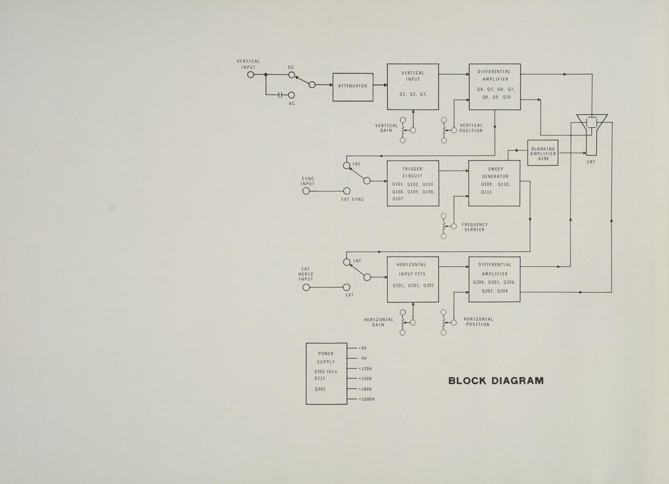
Near the end came the Circuit Description, often called the Theory of Operation: a stage-by-stage explanation of how the instrument works, usually introduced by a block diagram. The IO-102’s block diagram traces the vertical input through the attenuator, vertical input stage and differential amplifier to the CRT, and the sync input through the trigger circuit, sweep generator and horizontal amplifier. The following pages explain each block in the vocabulary a student would meet in a textbook (IO-102 manual). Gilmore credited this section, along with the step-by-step method, with making the manuals “a great deal of practical electronic theoretical education” as well as assembly instructions (Electronic Design). Heathkit Educational Systems, founded in 1974, grew directly out of these sections (Herald-Palladium, 7 September 2008).
8.3.11 Voltage charts, parts price list and the schematic
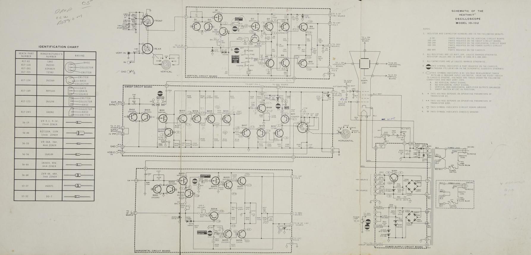
The back of the manual held reference material for the life of the instrument. Voltage charts gave the expected DC voltage at each transistor lead, drawn on views of each board. The Replacement Parts Price List repeated every part number with its 1971 price (a 1/2-watt resistor 10 cents, a 70 µF electrolytic $1.15, a TA2911 transistor $1.45, the power-supply circuit board $2.05, the manual itself $2.00). A Parts Order Form was packed with the kit (IO-102 manual, p. 95). Last came the schematic, printed as a wide fold-out titled “Schematic of the Heathkit Oscilloscope Model IO-102”, with the part designations used throughout the manual and voltages marked at key points.
8.4 The Kit Builder’s Guide
From the 1960s Heath separated the general lessons from the model-specific manual. The Kit Builder’s Guide (part 597-308 in the IO-102 era) was a short booklet packed with each kit, covering “Installing parts”, “Proper soldering” and “Resistor & capacitor codes”. Its cover drew the “Tools Needed”: long-nose pliers, diagonal cutters, wire strippers, 1/8-inch and 1/4-inch screwdrivers, and a soldering iron with a 1/8-inch plated chisel tip, 25 to 40 watts; a note adds that “a pencil-type soldering iron … will give the best results.” A copy bound into the HN-31 “Cantenna” dummy-load manual carries the “Heath / Schlumberger” logo of the 1960s–70s (Internet Archive, HN-31 manual).
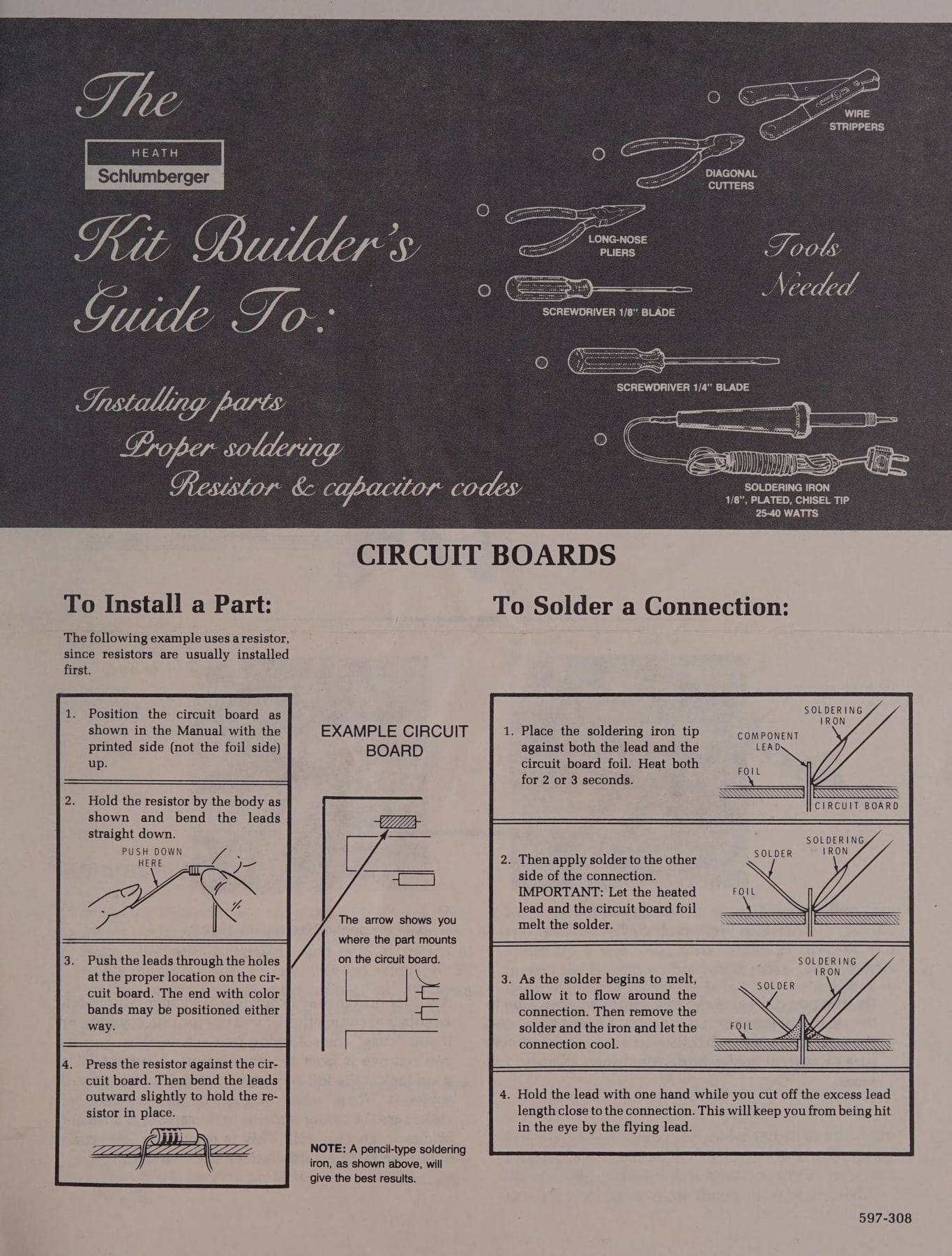
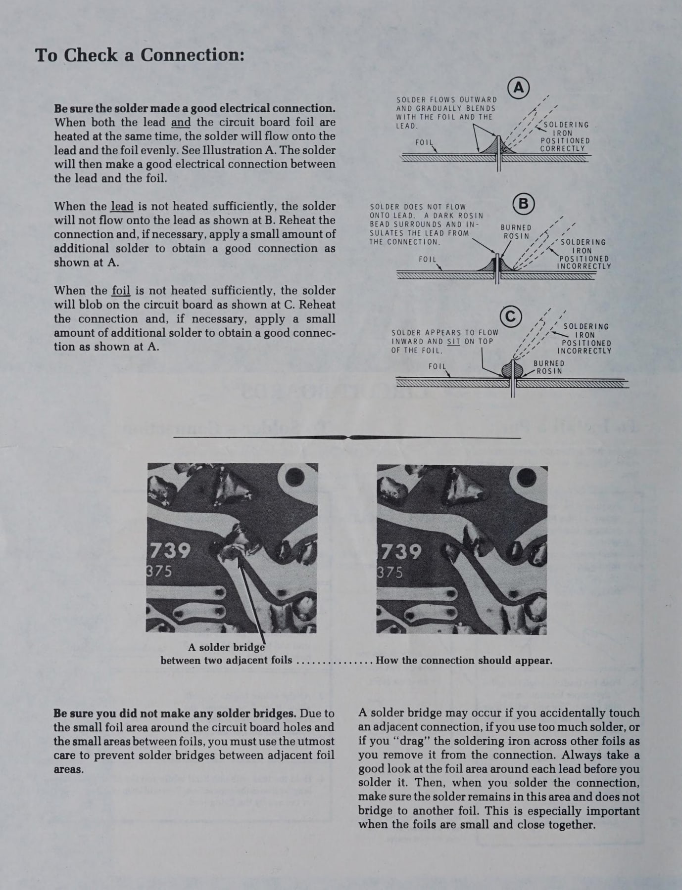
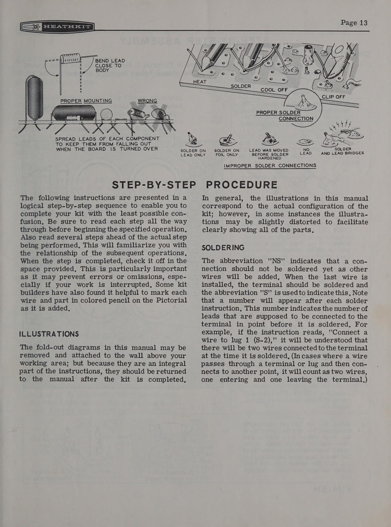
The soldering pages are exact. To solder a circuit-board connection, the builder places the iron tip against both the lead and the foil and heats both “for 2 or 3 seconds”; applies solder to the other side of the connection (“Let the heated lead and the circuit board foil melt the solder”); lets it flow around the connection and removes solder and iron; and then holds the lead while cutting off the excess, which “will keep you from being hit in the eye by the flying lead.” A companion page, “To Check a Connection”, draws three cases: A, solder that “flows outward and gradually blends with the foil and the lead”; B, a lead not heated enough, where “a dark rosin bead surrounds and insulates the lead”; and C, foil not heated enough, where the solder sits on top as a blob. Photographs show a solder bridge between adjacent foils and the same board after it was cleared (HN-31 manual).
8.4.1 Codes and identification
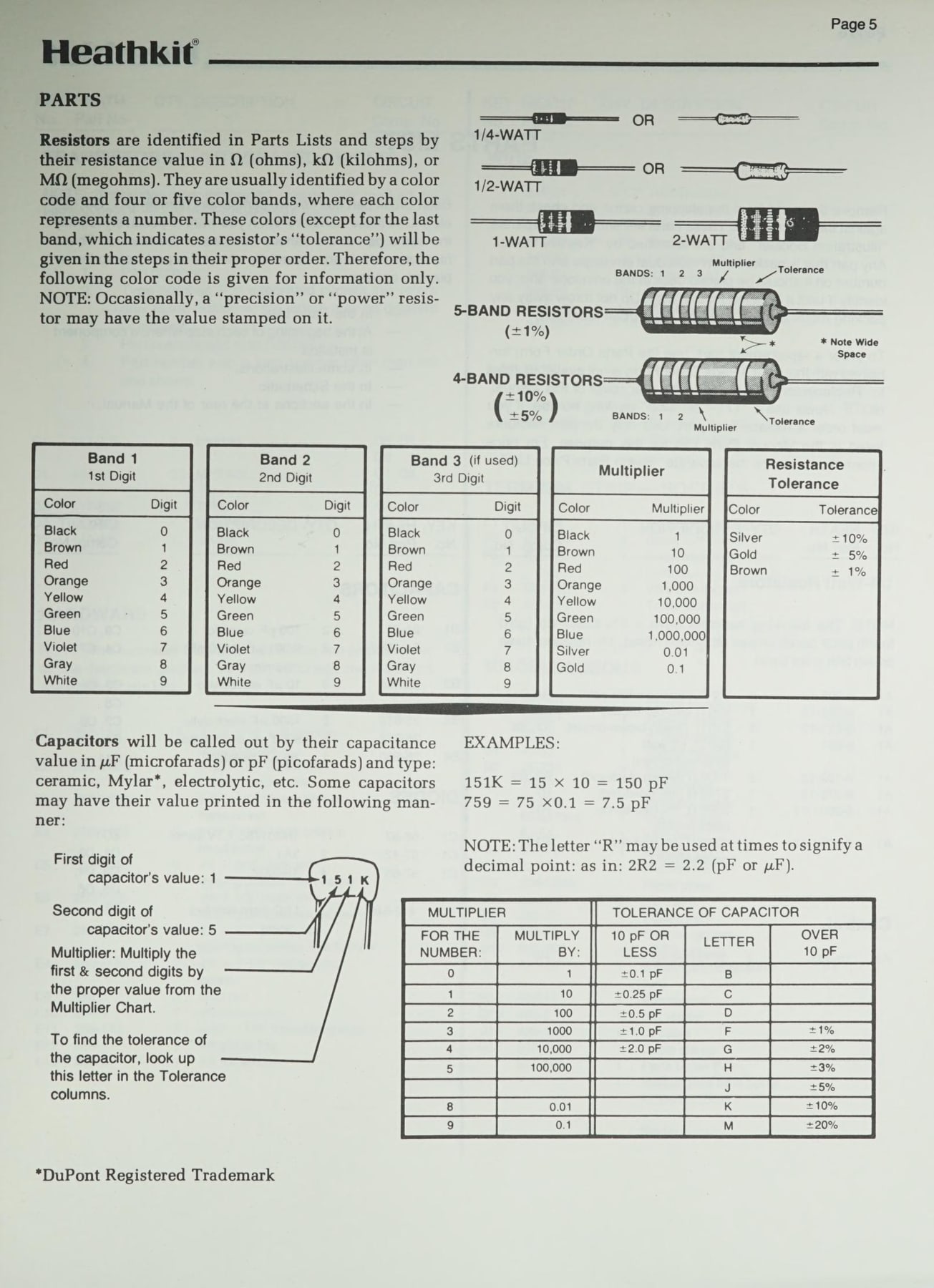
Every Heath manual taught component identification. The 1950s DX-40 transmitter manual printed a full-page Standard Color Code for resistors and for mica, ceramic, paper and tubular capacitors, each with a drawing of the part and a band-by-band key (Internet Archive, DX-40 manual). The Kit Builder’s Guide of the 1960s–70s reduced this to a “Resistor Color Code” table (first digit, second digit, multiplier, tolerance) with worked examples, and a capacitor page showing how to read printed codes (“151K = 15 × 10 = 150 pF”), with the note that an “R” may stand for a decimal point, as in 2R2 (HN-31 manual).
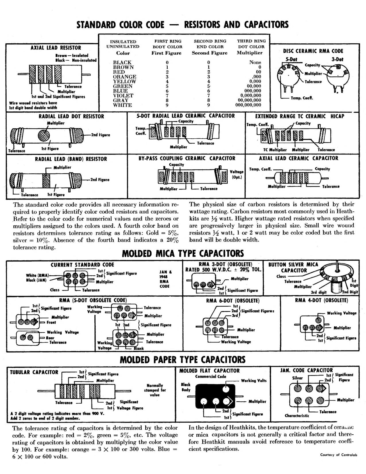
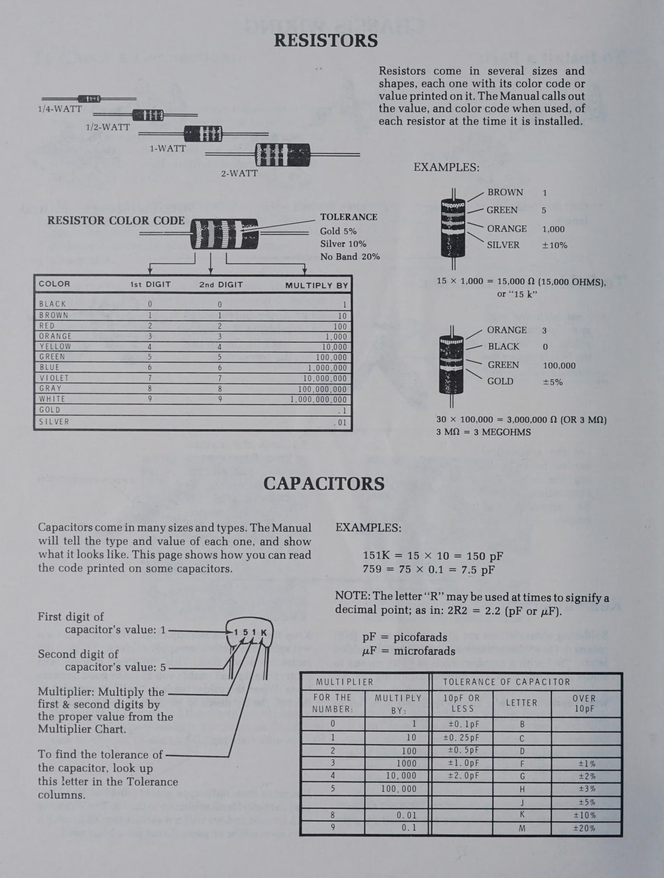
The manual’s own parts lists taught the codes by repetition. Because every resistor step gives the colours in words (“470 kΩ (yellow-violet-yellow)”), a builder who completed a few kits learned the code without studying it.
8.5 How the manual changed across the decades
8.5.1 The 1940s and early 1950s
Instruction sheets and short booklets written by the design engineer; typed text; blueprints and a photo print; steps as paragraphs. The V-4A of about 1950 is typical (V-4A manual).
8.5.2 Mid-1950s to early 1960s
Typeset booklets with separate step lines and check boxes, S/NS soldering boxes (V-7A), pictorials and colour-code charts inside the covers (DX-40). The printed circuit board arrives with the V-7 in 1955 (Brueschke and Mack). Manuals begin to carry a copyright line with a date, sometimes a precise print date: the IM-10 service-bench VTVM manual is marked “Copyright 1960 9/9/60” (Internet Archive, IM-10 manual).
8.5.3 Mid-1960s to 1970s
The classic Heath manual. It has a standard cover titled “Heathkit Assembly Manual” or “Assembly and Operation of the Heathkit …”, the atom emblem and a printed price, and inside it the modular parts lists, START/CONTINUE step pages with pictorials, fold-outs, X-ray views, “In Case of Difficulty”, circuit description, voltage charts, replacement-parts price list and fold-out schematic, with the general lessons moved into the Kit Builder’s Guide. The SB-200 linear amplifier manual shows the same pattern in amateur radio: a parts list with a drawing of the chassis, then a “Step-by-Step Procedure” page opening with notes on soldering and illustrations (Internet Archive, SB-200 manual).
8.5.4 The 1980s
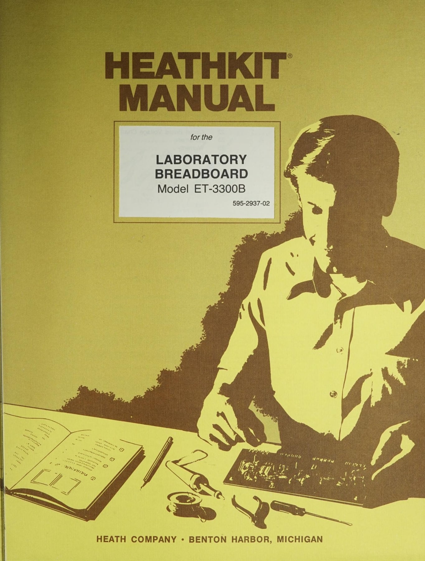
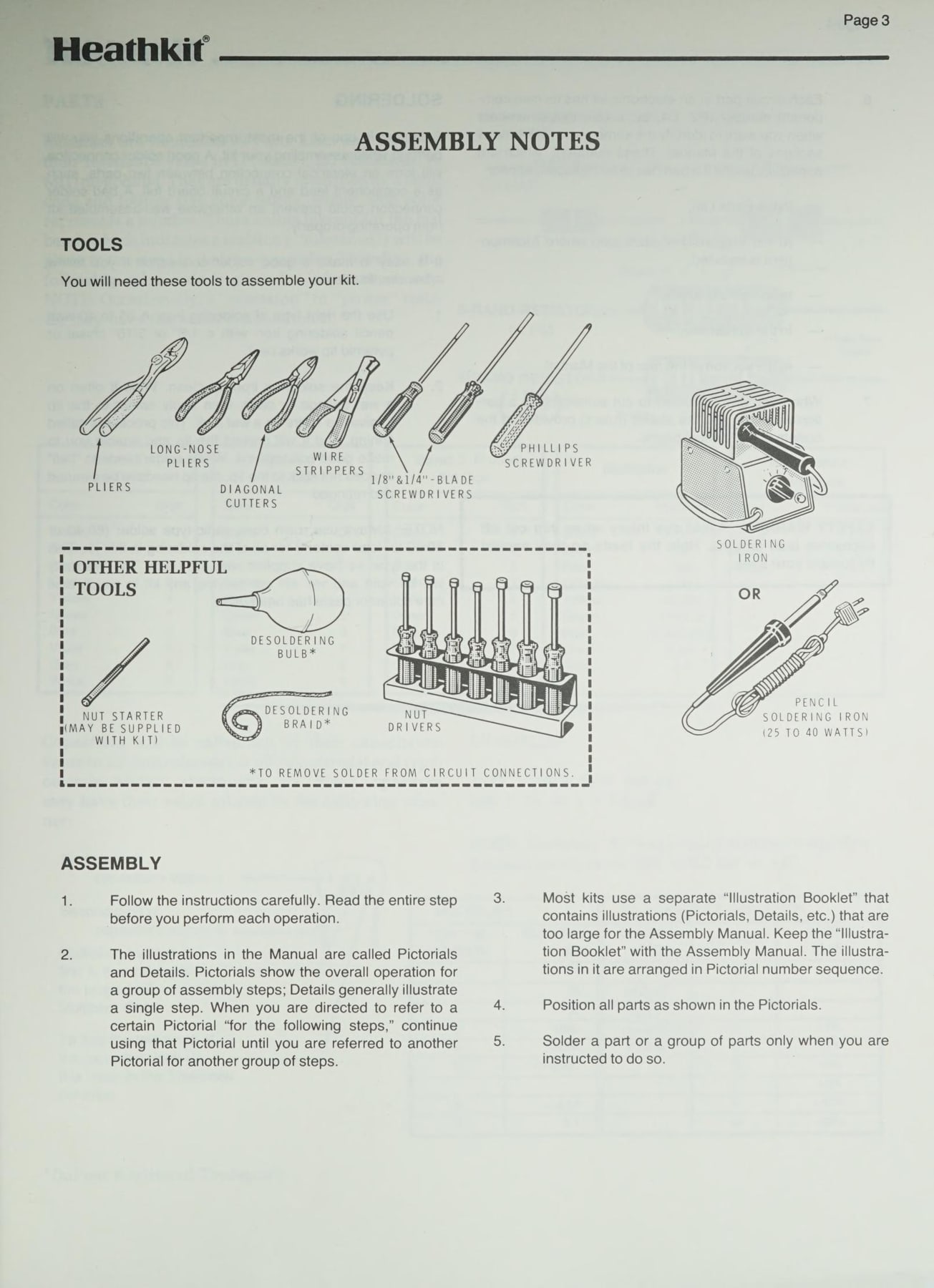
Manuals became larger in format, with the rounded “Heathkit” wordmark of the Zenith era and a cleaner sans-serif layout. The ET-3300B Laboratory Breadboard manual (copyright 1983, 595-2937-02) opens with “Assembly Notes” that draw the tools needed and then give numbered general rules, followed by a parts-identification section that shows resistors “identified in Parts Lists and steps by their resistance value” beside a colour-band key and capacitor code tables (Internet Archive, ET-3300B manual). The general guidance that had been in a separate Kit Builder’s Guide was folded back into the front of each manual. A “Heath Company Phone Directory”, with direct lines for ordering, replacement parts, technical assistance by product line, and the education and computer groups, appeared on the inside cover of manuals of this period (ET-3300B manual; HN-31 manual, later printing).
8.5.5 The last manuals, 1990
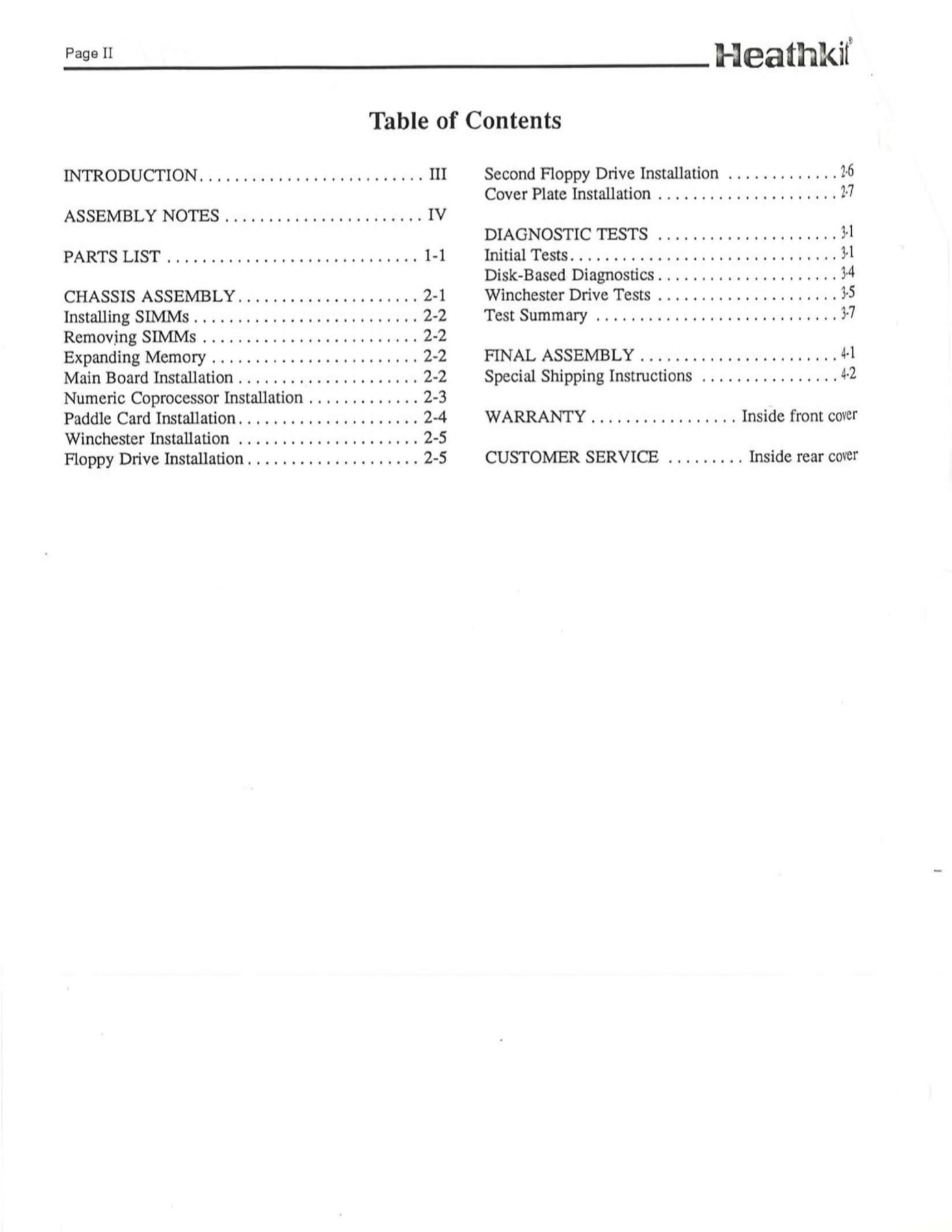
The H-5100 desktop computer (assembly manual 595-4696, copyright 1990) shows where the method ended. The manual is a loose-leaf binder section with chapter-numbered pages (Parts List 1-1, Chassis Assembly 2-1). The pictorials have moved into a separate “Illustration Booklet … arranged in the proper sequence, as called for in the assembly steps.” The tools list is four items: a #1 Phillips screwdriver, a 1/4-inch flat-blade screwdriver, and 3/16-inch and 1/4-inch nut drivers. No soldering iron is needed, because the builder installs finished boards, SIMM memory modules, a coprocessor on a “paddle card” and disk drives. A static-electricity caution appears on the parts list, and the “In Case of Difficulty” section has become “Diagnostic Tests”, with ROM-based and disk-based diagnostics (H-5100 assembly manual). The step-by-step form, the parts check against a pictorial and the proofbuild all remained; the soldering had gone.
Gilmore identified the cost of this thoroughness as one reason the kit business struggled late on: “Heath had significant assembly manual development expense, and the manuals were a great part of Heath’s success. This was a product cost that manufacturers of assembled products didn’t have” (Electronic Design). Brueschke and Mack list the same point among their causes of decline: kit design, “including the instruction manual, became a complex and time-consuming activity, which made Heath less responsive to changing technical advances” (Brueschke and Mack, p. 152).
8.6 Heath’s tools and accessories
Heath sold the tools its manuals called for. The Nostalgic Kits Central model matrix records GH-series soldering irons (GH-17 and GH-17A) in the late 1960s and a TK-1 tool set (Nostalgic Kits Central). Solder, a Nut Starter and, for some consumer kits, a simple meter came in the box. Accessory kits for a given model carried the parent’s number with an “A”: IMA- for meter accessories, SBA- for SB-line accessories, GRA- for television and radio accessories. The practice survives: the restarted company sells a GDP-1200 surface-mount soldering toolkit, a GDP-1800 magnifying loupe, and accessory kits numbered IGA-18, AJA-1510 and GCA-1006 (shop.heathkit.com).
8.7 Why it worked
The Heath manual worked because it was designed as a product and tested like one. It gave one action to a step, drew the result instead of photographing it, taught the codes by repeating them, printed a ruler on the page, and assumed that the builder would make mistakes and would need to be shown how to find them. Every page was checked by employees who were told to mark in red and not to improvise. Steve Jobs, in a 1995 interview that Heathkit Educational Systems later put on its home page, said the kits “would come with these detailed manuals about how to put this thing together and all the parts would be laid out in a certain way and color coded”, and that they “gave one the sense that one could build the things that one saw around oneself in the universe” (heathkit.com, archived January 2012).
Sources
- Frenzel, Lou. “Heathkit: An Employee’s Look Back” (interview with Chas Gilmore). Electronic Design, 30 November 2020. Link
- Brueschke, Erich E., and Michael Mack. “The History of the Heath Companies and Heathkits: 1909 to 2019.” The AWA Review 32 (2019). PDF via Wayback
- Heathkit Assembly Manual, Solid State 5” Oscilloscope Model IO-102, 595-1285-01, 1971. Internet Archive
- Heathkit Assembly Manual, Volt-Ohm-Milliammeter Model IM-105, 595-1335. Internet Archive
- Assembly and Operation of the Heathkit Solid State VOM Model IM-25, 595-1042-02, 1967. Internet Archive
- Heathkit Assembly Manual, “Cantenna” Dummy RF Load Model HN-31, 595-527-03 (with Kit Builder’s Guide 597-308). Internet Archive
- Heathkit Assembly Manual, Linear Amplifier Model SB-200. Internet Archive
- Heathkit Assembly Manual, Service Bench VTVM Model IM-10, 595-362, 1960. Internet Archive
- Heathkit Manual for the Laboratory Breadboard Model ET-3300B, 595-2937-02, 1983. Internet Archive
- Heathkit H-5100 Assembly Manual (595-4696, 1990), Illustration Booklet and Proofbuild Report (QA form 4514-1). Internet Archive
- Heathkit V-4A Vacuum Tube Voltmeter manual. Internet Archive
- Heathkit DX-40 Amateur Transmitter manual. Internet Archive
- Allen, Kevin. “Heathkit moving to St. Joe Township.” Herald-Palladium, 7 September 2008. Link
- heathkit.com, archived 5 January 2012. Wayback Machine
- Nostalgic Kits Central, Heathkit model matrix. Link
- Heathkit shop. Link
Comments (0)